bài giảng lí thuyết về RTL chuong 2
tài liệu nói về cách học RTL
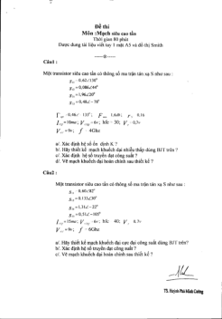
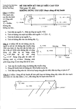
Môn: Kỹ thuật siêu cao tần 4 tài liệu
Trường: Trường Đại học Bách khoa - Đại học Quốc gia Thành phố Hồ Chí Minh 721 tài liệu
Tác giả:

Preview text:
Digital Design Chapter 5: Register-Transfer Level (RTL) Design
Slides to accompany the textbook Digital Design, First Edition,
by Frank Vahid, John Wiley and Sons Publishers, 2007. http://www.ddvahid.com Copyright © 2007 Frank Vahid
Instructors of courses requiring Vahid's Digital Design textbook (published by John Wiley and Sons) have permission to modify and use these slides for customary course-related activities, subject to keep Digit ing this al co Design
pyright notice in place and unmodified. These slides may be posted as unanimated pdf versions on publicly-accessible course websites.. PowerPoint source (or pdf with anima Copy tions) may ri notght be p © 2006
osted to publicly-accessible websites, but may be posted for students on internal protected sites or distributed directly to students by other electronic 1 means.
Instructors may make printouts of the slides available to students for a reasonable photocopying charge, without incurring royalties. Any other use requires explicit permission. Instructors may obtain Po Frank werPoint Vahi sou d
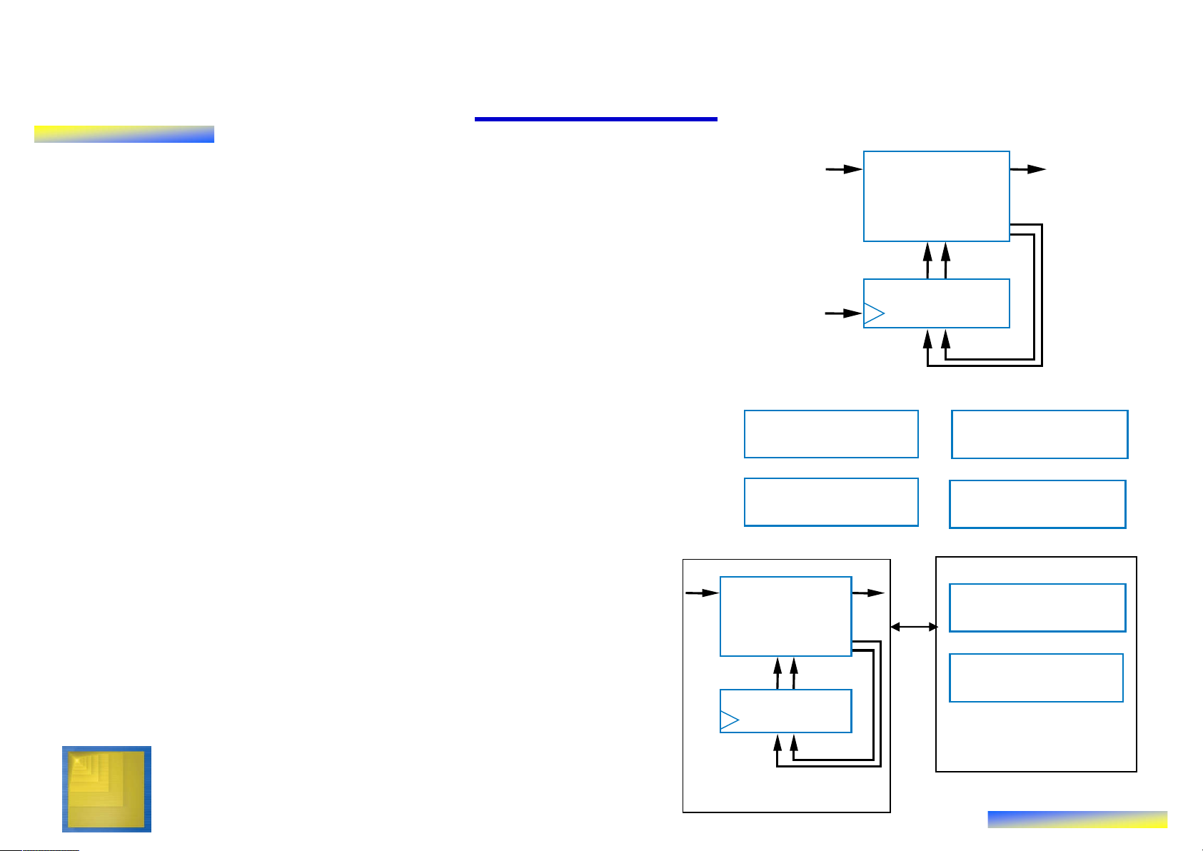
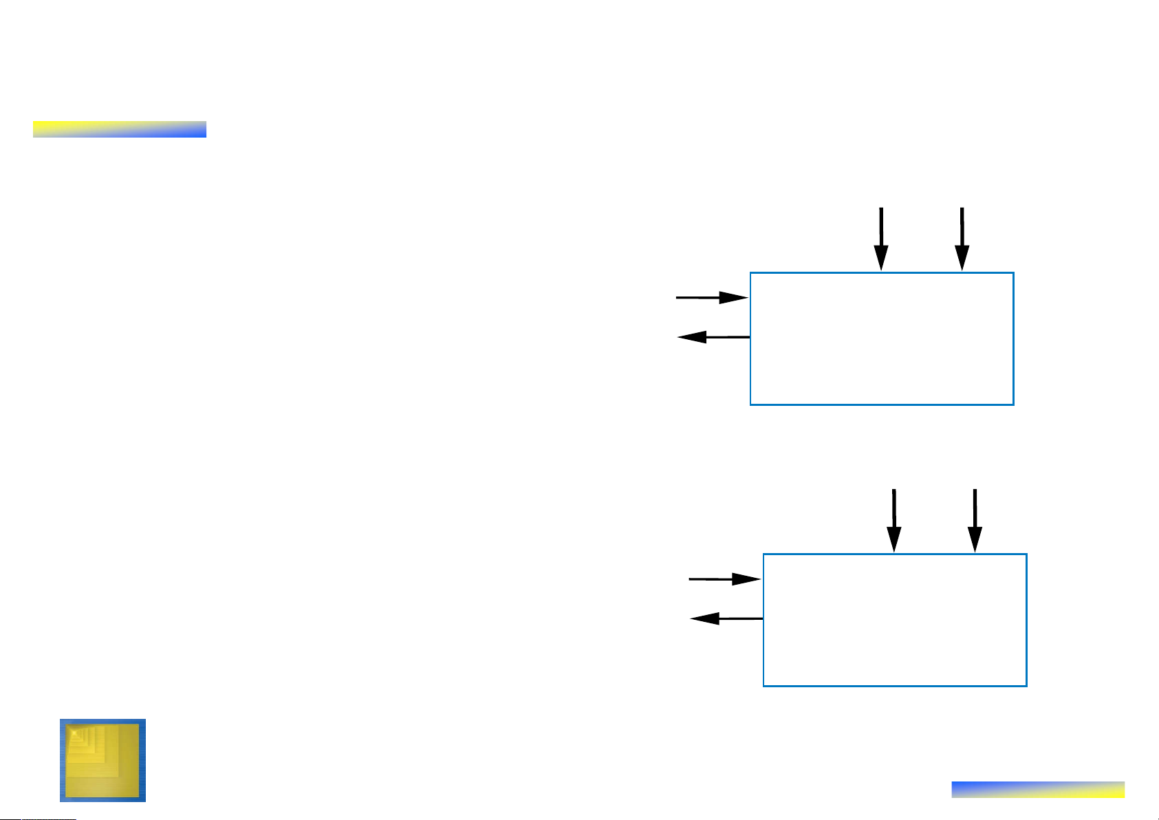
rce or obtain special use permissions from Wiley – see http://www.ddvahid.com for information. 5.1 Introduction ts ts bi bo u • Chapter 3: Controllers u FSM tp inp Combinational FSM ou
– Control input/output: single bit (or just a logic n1
few) representing event or state n0
– Finite-state machine describes s1 s0
behavior; implemented as state register State register clk and combinational logic • Chapter 4: Datapath components
– Data input/output: Multiple bits Register Comparator
collectively representing single entity
– Datapath components included ALU Register file
registers, adders, ALU, comparators, register files, etc. •
This chapter: custom processors bi bo Combinational Register file
– Processor: Controller and datapath logic n1
components working together to n0 implement an algorithm s1 s0 ALU State register Datapath Digital Design Copyright © 2006 Controller 2 Frank Vahid
Note: Slides with animation are denoted with a small red "a" near the animated items
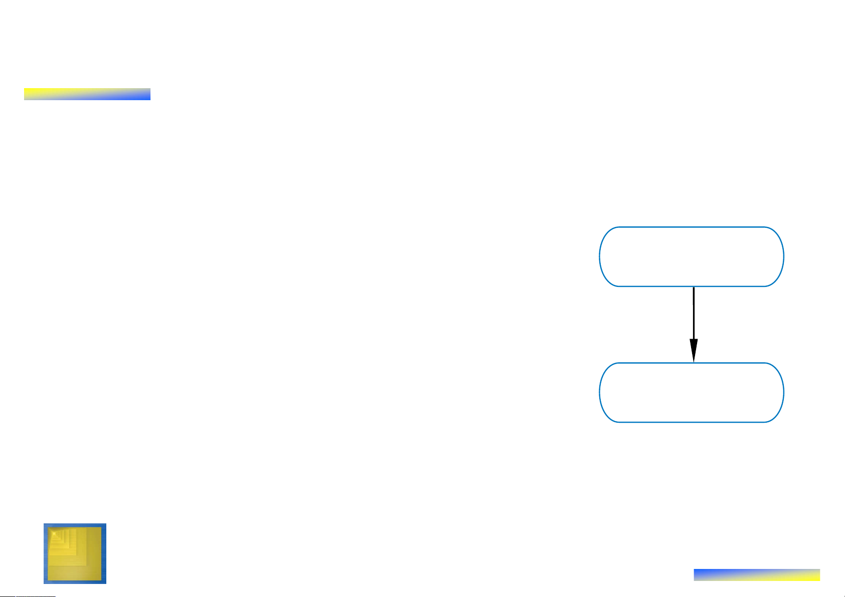
RTL Design: Capture Behavior, Convert to Circuit • Recall
– Chapter 2: Combinational Logic Design
• First step: Capture behavior (using equation or truth table)
• Remaining steps: Convert to circuit Capture behavior
– Chapter 3: Sequential Logic Design
• First step: Capture behavior (using FSM)
• Remaining steps: Convert to circuit
• RTL Design (the method for creating custom processors) Convert to circuit
– First step: Capture behavior (using high-
level state machine, to be introduced)
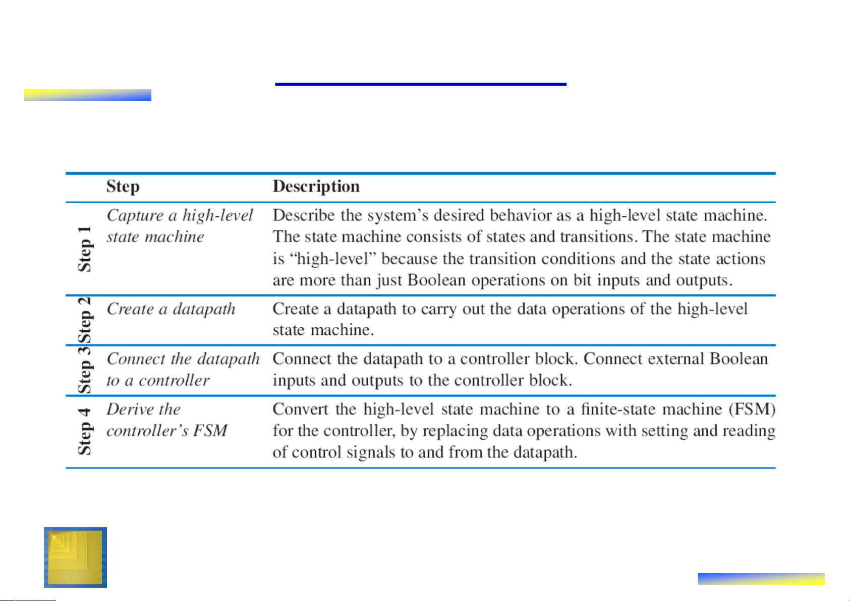
– Remaining steps: Convert to circuit Digital Design Copyright © 2006 3 Frank Vahid 5.2 RTL Design Method Digital Design Copyright © 2006 4 Frank Vahid
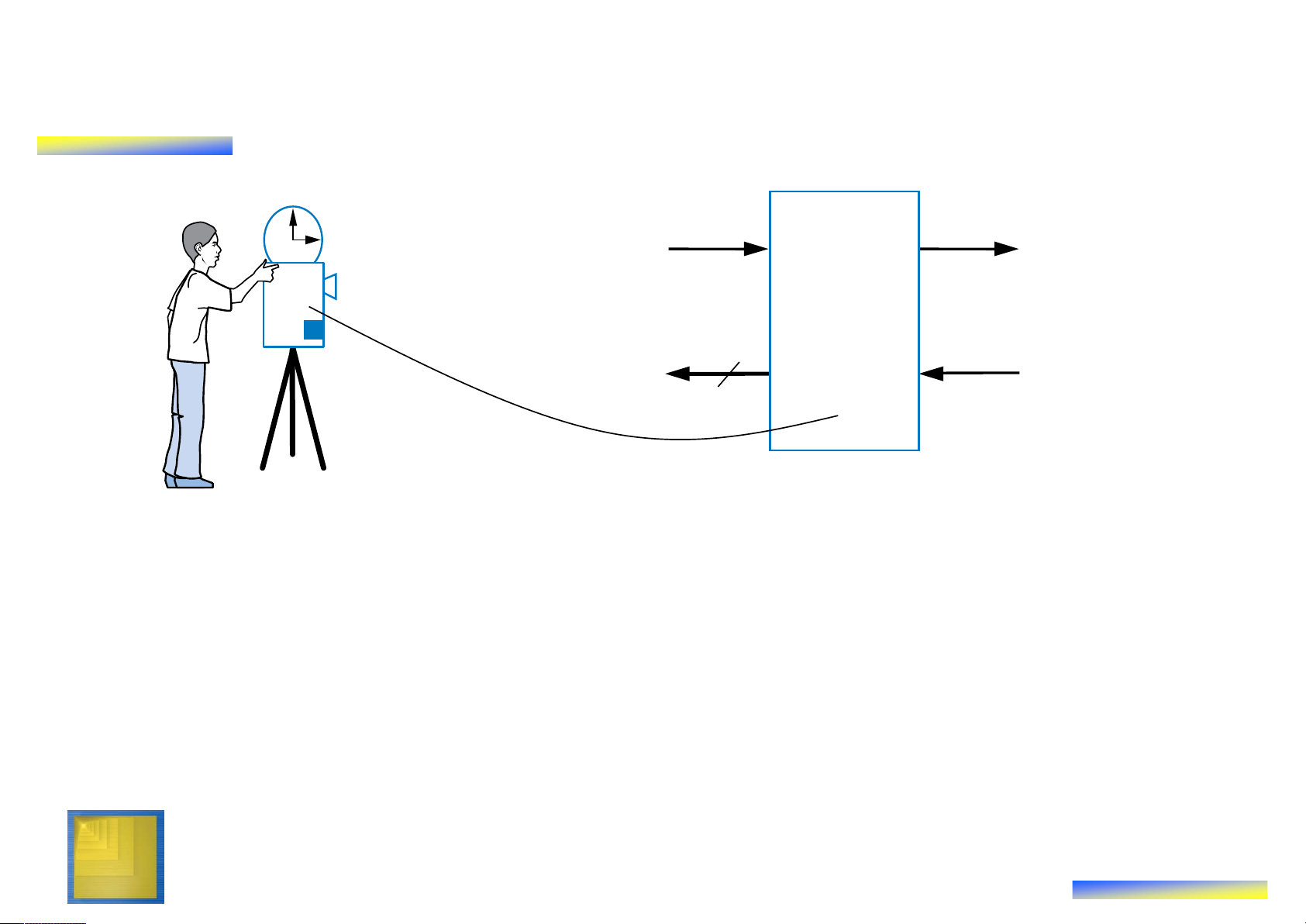
RTL Design Method: “Preview” Example • Soda dispenser s a
– c: bit input, 1 when coin deposited
– a: 8-bit input having value of c Soda deposited coin d dispenser
– s: 8-bit input having cost of a processor soda
– d: bit output, processor sets to s a 25 1 when total value of 25 deposited coins equals or 1 0 1 50 0 0 exceeds cost of a soda c Soda tot tot : : d dispenser a 0 1 processor 0 25 50
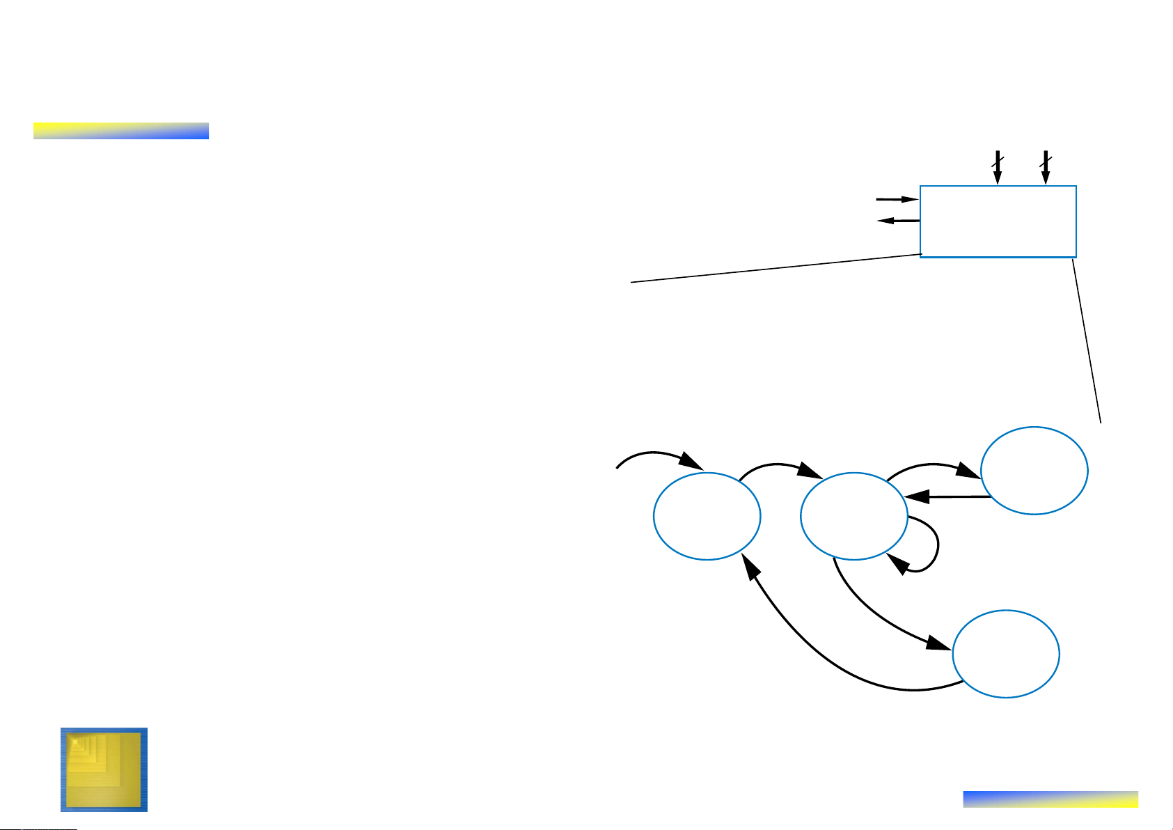
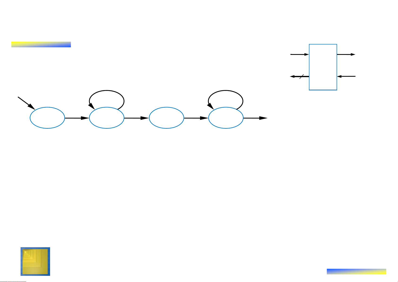
How can we precisely describe this Digital Design Copyright © 2006 processor’s behavior? 5 Frank Vahid Preview Example: Step 1 –
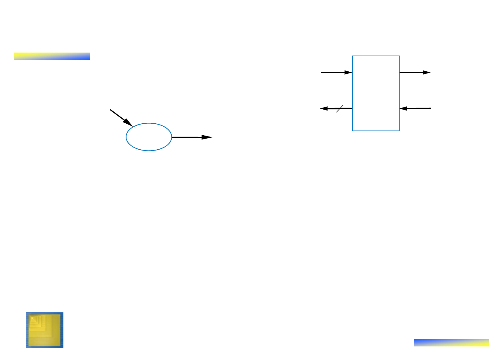
Capture High-Level State Machine s a •
Declare local register tot 8 8 c •
Init state: Set d=0, tot=0 Soda d dispenser processor •
Wait state: wait for coin
– If see coin, go to Add state
Inputs: c (bit), a (8 bits), s (8 bits) •
Add state: Update total value: Outputs: d (bit) tot = tot + a Local registers: tot (8 bits)
– Remember, a is present coin’s c value Add
– Go back to Wait state Init Wait •
In Wait state, if tot >= s, go to tot=tot+a Disp(ense) state d=0 c’*(totc’*(tot•
Disp state: Set d=1 (dispense tot=0 soda) Disp
– Return to Init state d=1 Digital Design Copyright © 2006 6 Frank Vahid Preview Example: Step 1 –
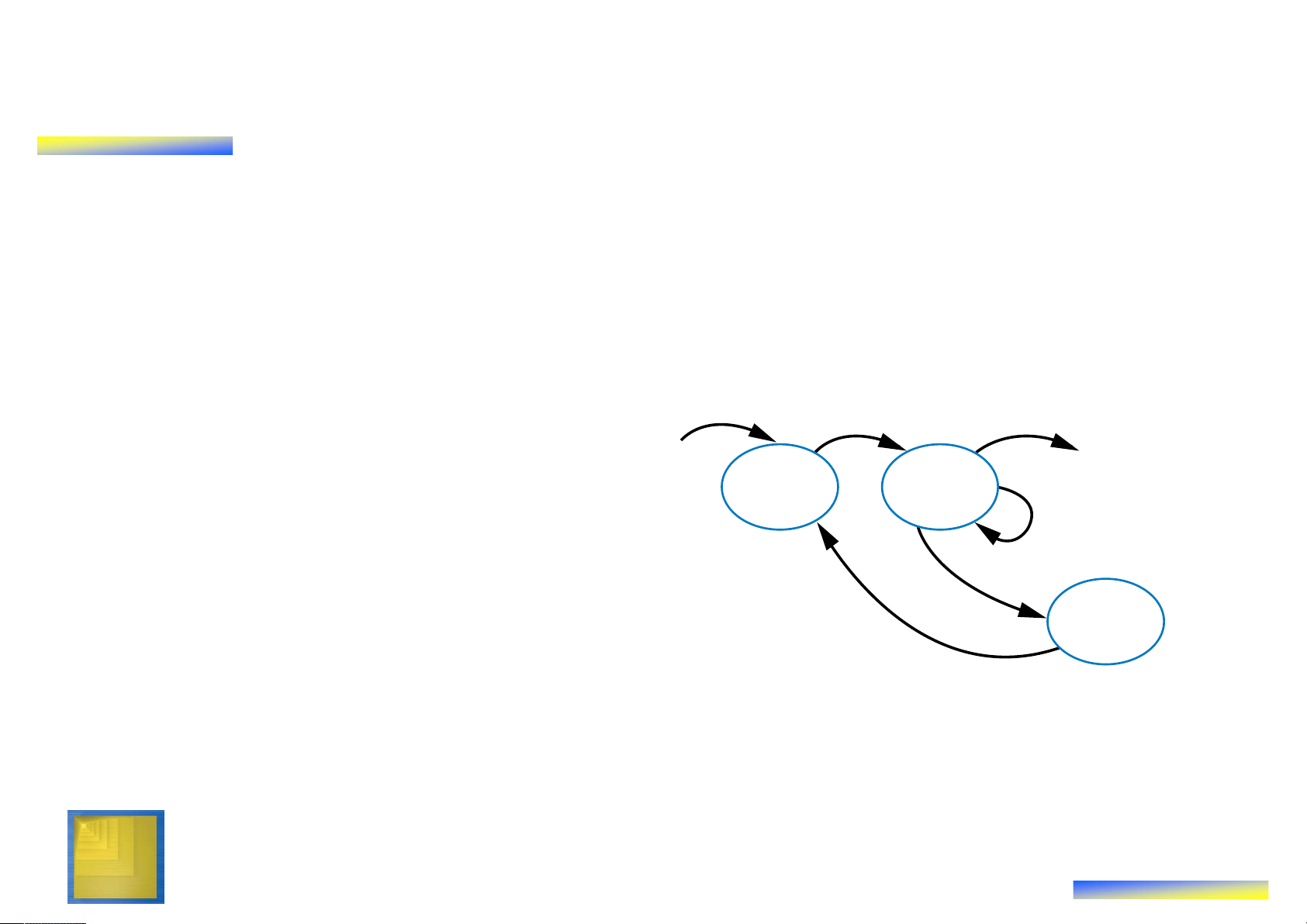
Create a High-Level State Machine
• Let’s consider each step of the RTL design process in more detail
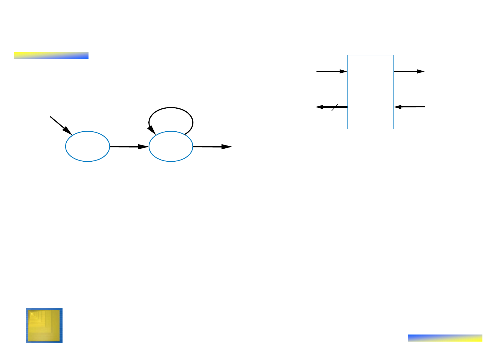
Inputs : c (bit), a (8 bits) , s (8 bits) • Step 1 Outputs : d (bit) Local reg isters: tot (8 bits) – Soda dispenser example – Not an FSM because: c
• Multi-bit (data) inputs a and s Init Wait • Local register tot tot= tot+a
• Data operations tot=0, tot d=0 c’ (tottot=tot+a. c’(tottot=0
– Useful high-level state machine: Disp
• Data types beyond just bits d=1 • Local registers
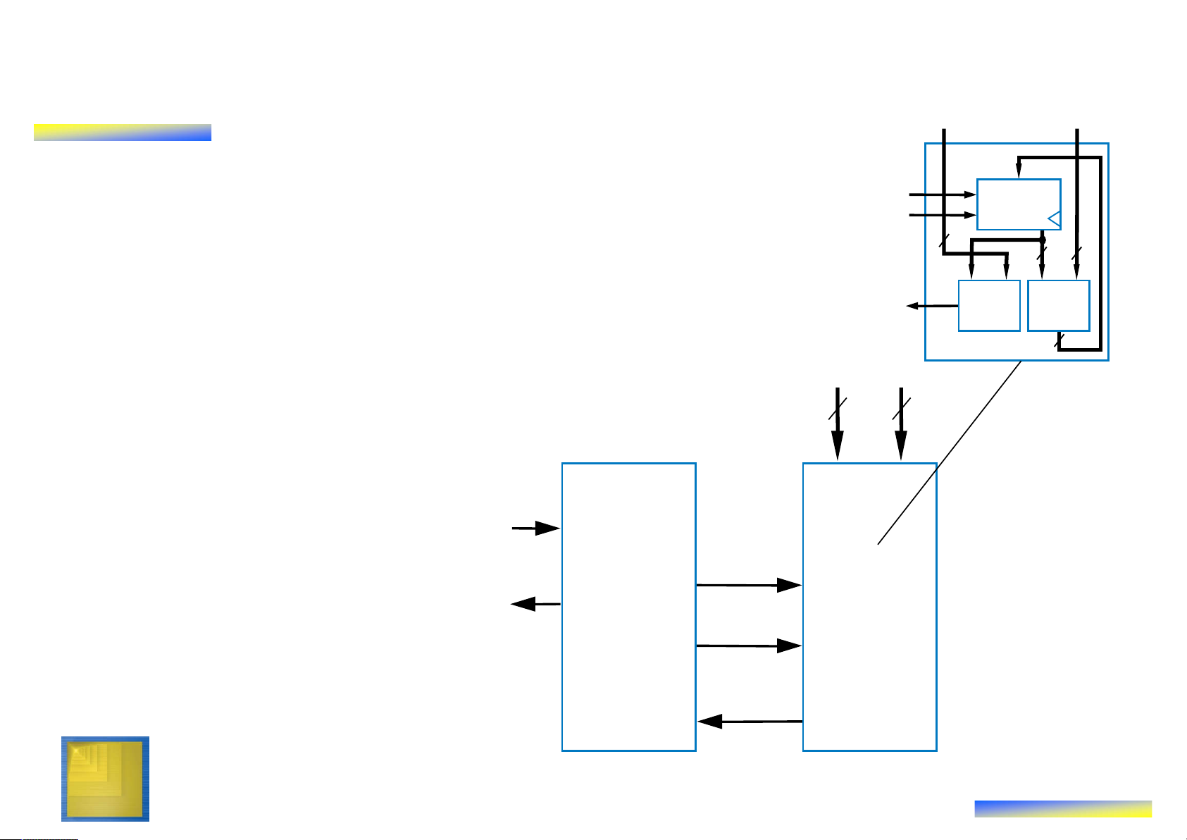
• Arithmetic equations/expressions Digital Design Copyright © 2006 7 Frank Vahid Preview Example: Step 2 – Create Datapath
Inputs : c (bit), a(8 bits) , s (8 bits) O utputs : d (bit)
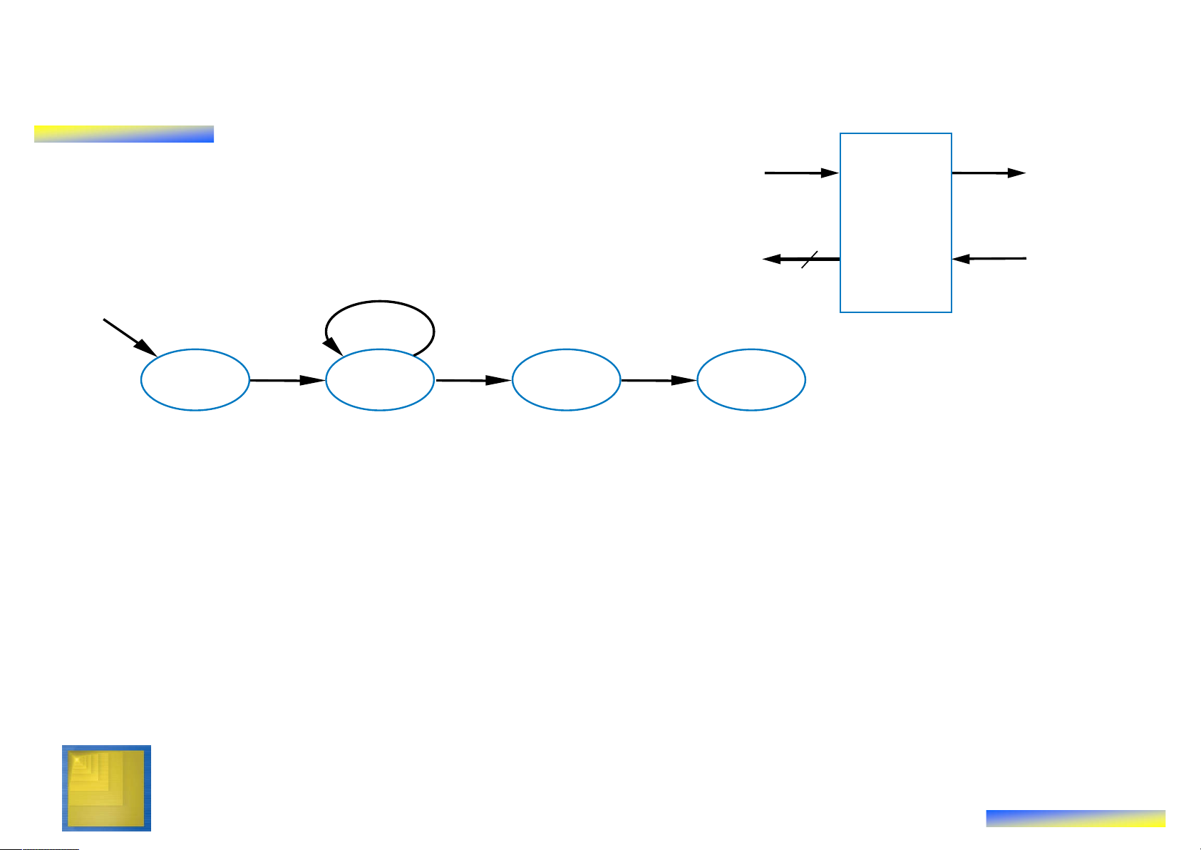
Local reg isters : tot (8 bits) • Need tot register c Add • Need 8-bit comparator Init Wait tot= tot+a d=0 c c‘ (tot‘
to compare s and tot tot=0 (totDisp • Need 8-bit adder to d=1 s a perform tot = tot + a • Wire the components as needed for above tot_ld ld tot tot_clr clr • Create control 8 input/outputs, give 8 8 them names tot_lt_s 8-bit 8-bit < adder 8 Datapath Digital Design Copyright © 2006 8 Frank Vahid Preview Example: Step 3 –
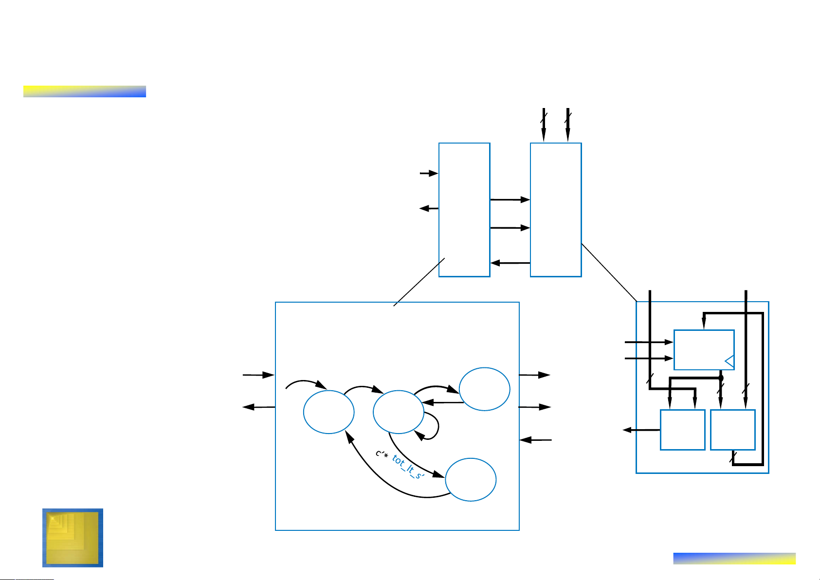
Connect Datapath to a Controller s a • Controller’s inputs tot_ld ld tot – External input c tot_clr clr 8 (coin detected) 8 8 8-bit – Input from datapath tot_lt_s 8-bit < adder comparator’s output, 8 Datapath which we named s a tot_lt_s 8 8 • Controller’s outputs – External output d c (dispense soda) – Outputs to datapath d tot_ld to load and clear the tot register tot_clr Controller Datapath tot_lt_s Digital Design Copyright © 2006 9 Frank Vahid Preview Example: Step 4 – Derive the Controller’s FSM s a • Same states 8 8 and arcs as c high-level state machine d tot_ld oller ath tot_clr • But set/read ap Contr Dat datapath tot_lt_s s a control signals Inputs:: c, tot_lt_s (bit) for all datapath
Outputs:d, tot_ld, tot_clr (bit) tot_ld ld tpt tot_ld tot_clr clr operations and c c 8 Add 8 8 tot_clr conditions d Init Wait tot_ld=1 tot_lt_s tot_lt_s 8-bit 8-bit < adder d=0 c’*tot_lt_s 8 tot_clr=1 Datapath Disp d=1 Digital Design Controller Copyright © 2006 10 Frank Vahid
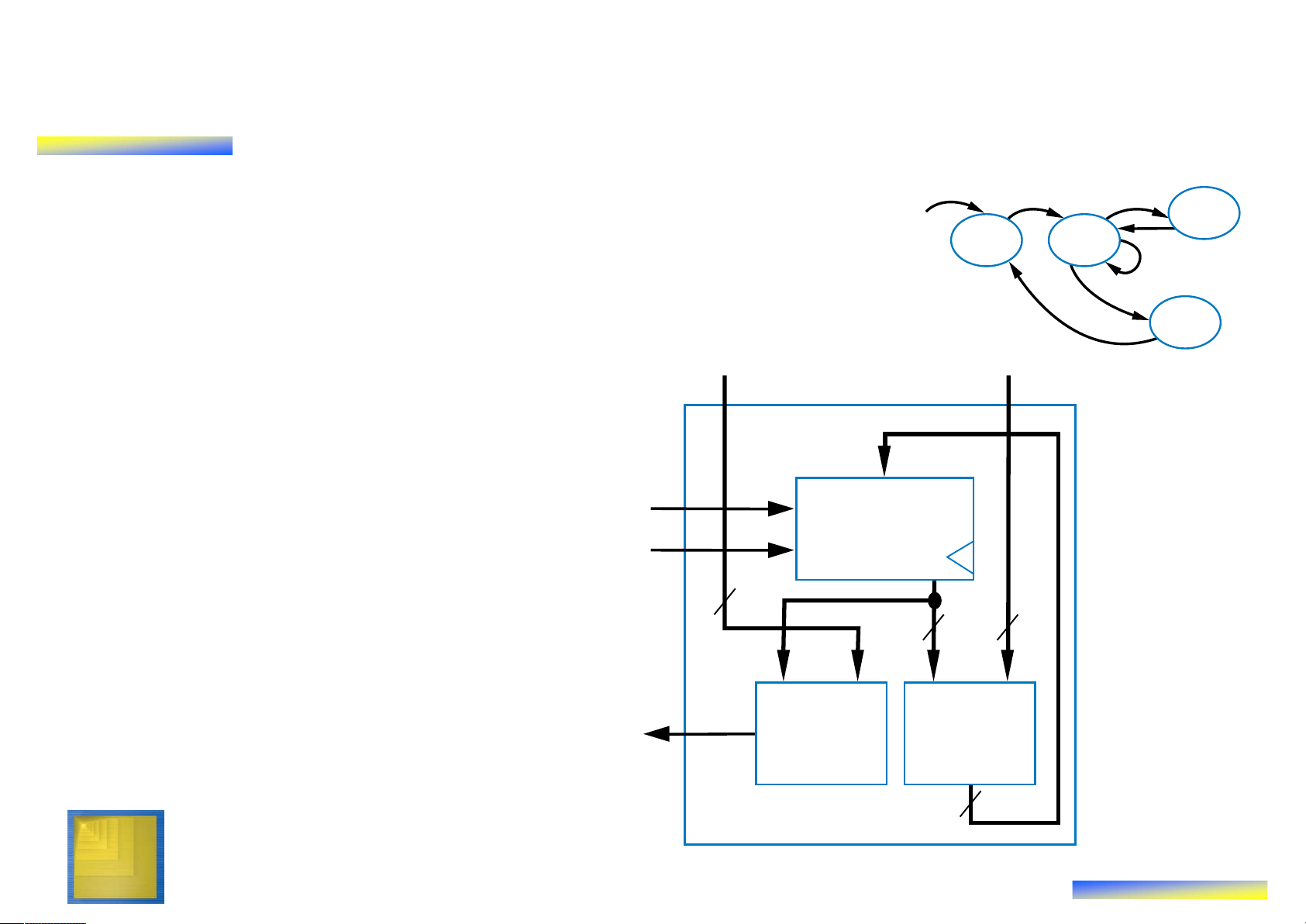
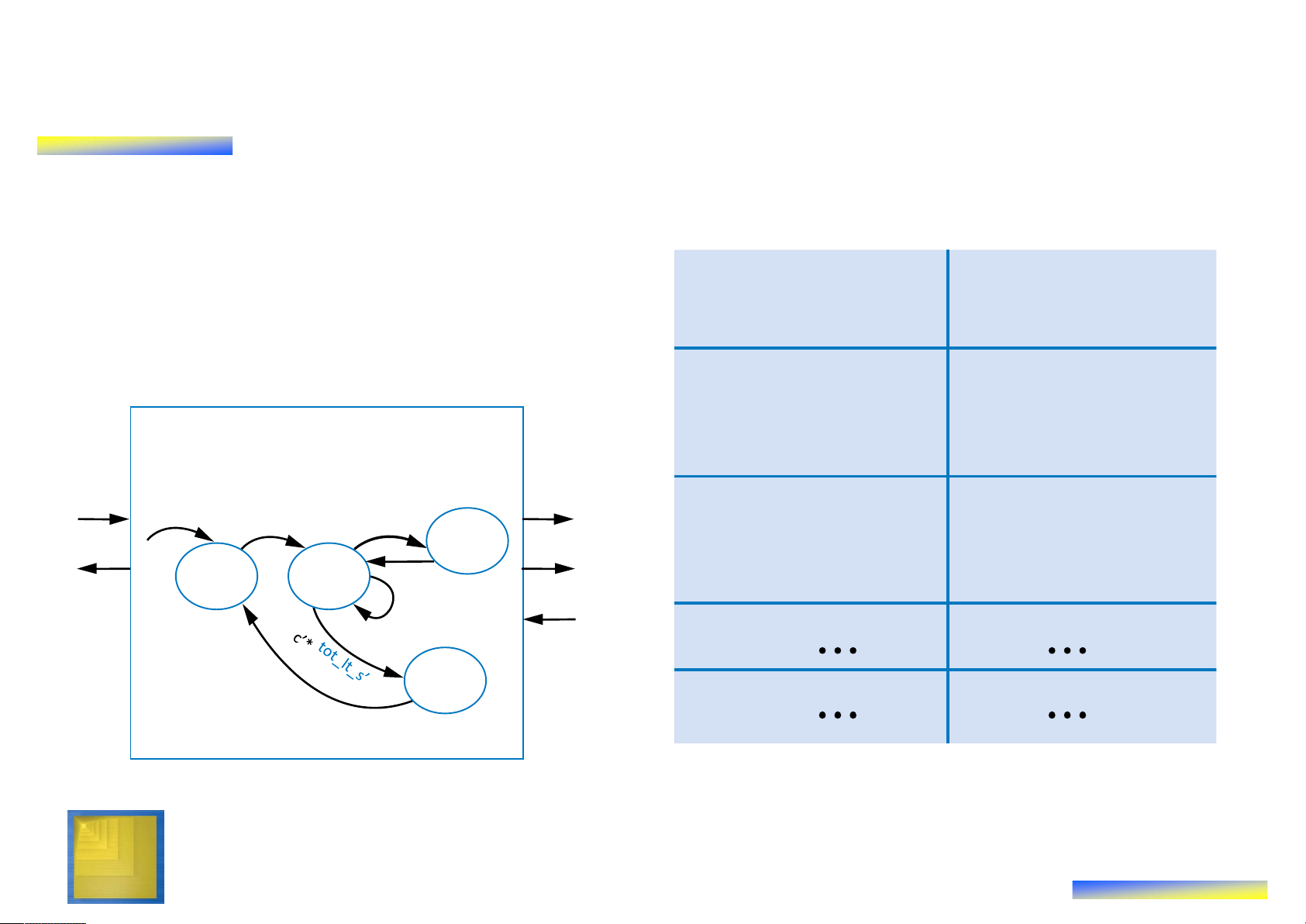
Preview Example: Completing the Design • Implement the FSM as a state register and logic tot t t ot o – As in Ch3 _ lt t_ _ _ c s ld lr s1 s0 c n1 n0 d – Table shown on right 0 0 0 0 0 1 0 0 1 0 0 0 1 0 1 0 0 1 Init 0 0 1 0 0 1 0 0 1 Inputs:: c, tot_lt_s (bit) 0 0 1 1 0 1 0 0 1
Outputs: d, tot_ld, tot_clr (bit) tot_ld 0 1 0 0 1 1 0 0 0 c c it 0 1 0 1 0 1 0 0 0 a Add tot_clr W 0 1 1 0 1 0 0 0 0 d Init Wait tot_ld=1 0 1 1 1 1 0 0 0 0 tot_lt_s 1 0 0 0 0 1 0 1 0 d=0 c’*tot_lt_s dd A tot_clr=1 Disp p 1 1 0 0 0 0 1 0 0 is D d=1 Controller Digital Design Copyright © 2006 11 Frank Vahid
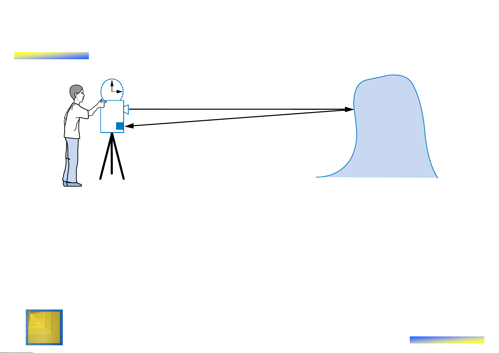
Example: Laser-Based Distance Measurer T (in seconds) laser D Object of interest sensor 2D = T sec * 3*108 m/sec
• Example of how to create a high-level state machine to
describe desired processor behavior
• Laser-based distance measurement – pulse laser,
measure time T to sense reflection
– Laser light travels at speed of light, 3*108 m/sec
– Distance is thus D = T sec * 3*108 m/sec / 2 Digital Design Copyright © 2006 12 Frank Vahid
Step 1 Example: Laser-Based Distance Measurer T (in seconds) B L laser from button to laser Laser-based distance sensor D 16 measurer S to display from sensor • Inputs/outputs
– B: bit input, from button to begin measurement
– L: bit output, activates laser
– S: bit input, senses laser reflection
– D: 16-bit output, displays computed distance Digital Design Copyright © 2006 13 Frank Vahid
Step 1 Example: Laser-Based Distance Measurer from button B L Laser- to laser Inputs: B, S (1 bit each) based Outputs: L (bit), D (16 bits) distance D 16 measurer S to display from sensor S0 ? a L = 0 (laser off) D = 0 (distance = 0)
• Step 1: Create high-level state machine
• Begin by declaring inputs and outputs
• Create initial state, name it S0
– Initialize laser to off (L=0)
– Initialize displayed distance to 0 (D=0) Digital Design Copyright © 2006 14 Frank Vahid
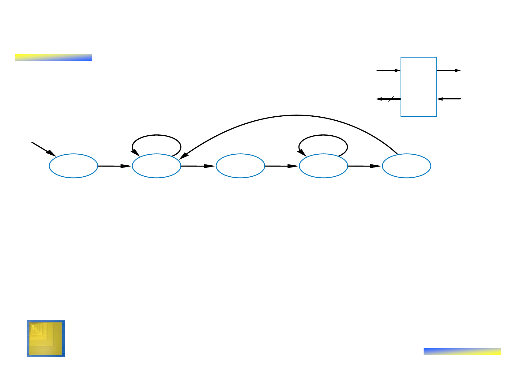
Step 1 Example: Laser-Based Distance Measurer Inputs: B, S (1 bit each) from button B L Laser- to laser Outputs: L (bit), D (16 bits) based distance B’ (button not pressed) D 16 measurer S to display from sensor a S0 S1 ? B L = 0 (button D = 0 pressed)
• Add another state, call S1, that waits for a button press
– B’ – stay in S1, keep waiting
– B – go to a new state S2 Q: What should S2 do? A: Turn on the laser a Digital Design Copyright © 2006 15 Frank Vahid
Step 1 Example: Laser-Based Distance Measurer Inputs: B, S (1 bit each) from button B L Laser- to laser Outputs: L (bit), D (16 bits) based distance D 16 measurer S to display from sensor B’ S0 S1 S2 S3 B L = 0 L = 1 L = 0 a D = 0 (laser on) (laser off)
• Add a state S2 that turns on the laser (L=1)
• Then turn off laser (L=0) in a state S3
Q: What do next? A: Start timer, wait to sense reflection a Digital Design Copyright © 2006 16 Frank Vahid
Step 1 Example: Laser-Based Distance Measurer B L from buton Inputs: B, S (1 bit each) to laser Outputs: L (bit), D (16 bits) Laser-based distance
Local Registers: Dctr (16 bits) D 16 measurer S to display from sensor B’ S’ (no reflection) S (reflection) S0 S1 S2 S3 ? B L = 0 Dctr = 0 L = 1 L = 0 a D = 0 (reset cycle Dctr = Dctr + 1 count) (count cycles)
• Stay in S3 until sense reflection (S)
• To measure time, count cycles for which we are in S3
– To count, declare local register Dctr
– Increment Dctr each cycle in S3
– Initialize Dctr to 0 in S1. S2 would have been O.K. too Digital Design Copyright © 2006 17 Frank Vahid
Step 1 Example: Laser-Based Distance Measurer B L from buton to laser Laser-based Inputs: B, S (1 bit each) Outputs: L (bit), D (16 bits) distance D 16 measurer S
Local Registers: Dctr (16 bits) to display from sensor B’ S’ a S0 S1 S2 S3 S4 B S L = 0 Dctr = 0 L = 1 L=0 D = Dctr / 2 D = 0 Dctr = Dctr + 1 (calculate D)
• Once reflection detected (S), go to new state S4 – Calculate distance
– Assuming clock frequency is 3x10⁸, Dctr holds number of meters, so D=Dctr/2
• After S4, go back to S1 to wait for button again Digital Design Copyright © 2006 18 Frank Vahid Step 2: Create a Datapath • Datapath must – Implement data storage
– Implement data computations
• Look at high-level state machine, do three substeps
– (a) Make data inputs/outputs be datapath inputs/outputs
– (b) Instantiate declared registers into the
datapath (also instantiate a register for each Instantiate: to data output) introduce a new
– (c) Examine every state and transition, and component into a
instantiate datapath components and
connections to implement any data design. computations Digital Design Copyright © 2006 19 Frank Vahid
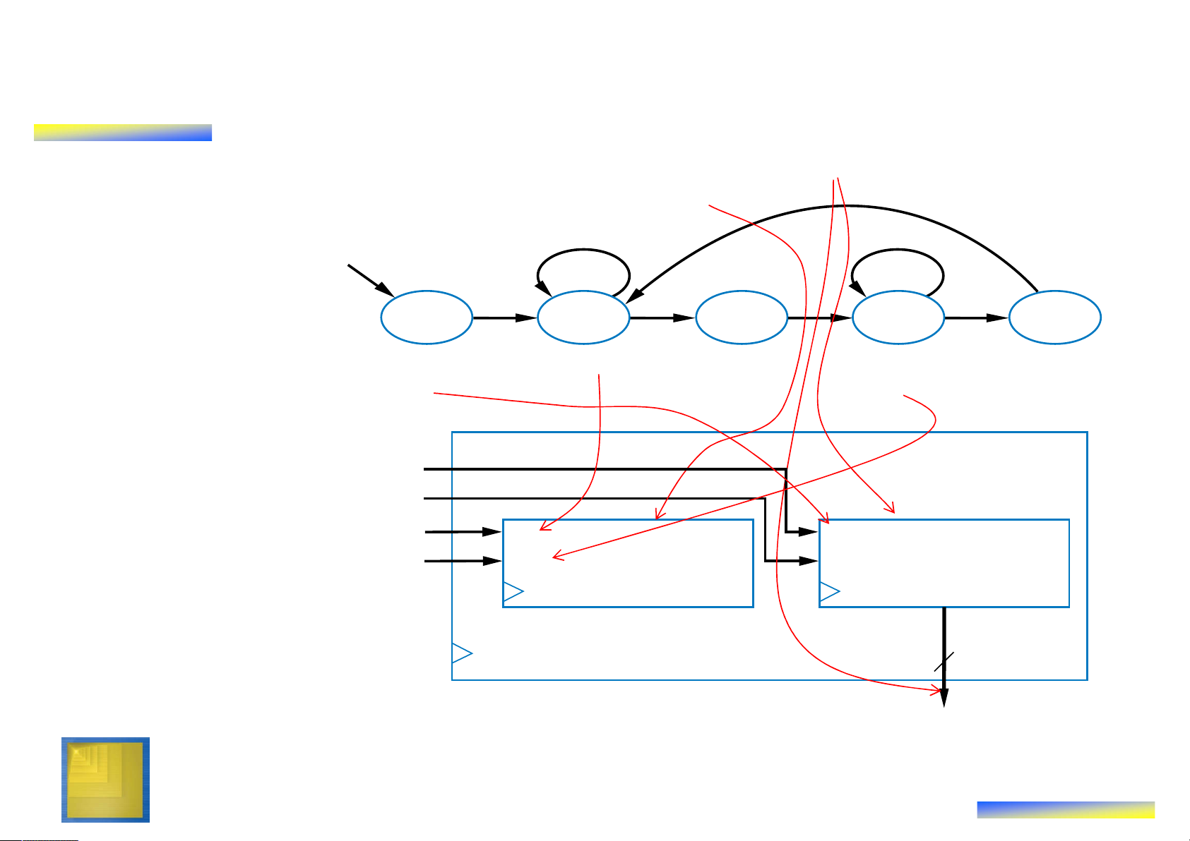
Step 2 Example: Laser-Based Distance Measurer Inputs: B, S (1 bit each) Outputs: L (bit), D (16 bits) (a) Make data
Local Registers: Dctr (16 bits) inputs/outputs be datapath B‘ S‘ inputs/outputs (b) Instantiate declared registers into the S0 S1 S2 S3 S4 B S datapath (also instantiate a L = 0 Dctr = 0 L = 1 L=0 D = Dctr / 2 D = 0 Dctr = Dctr + 1 (calculate D) register for each data output) a (c) Examine every Datapath Dreg_clr state and Dreg_ld transition, and instantiate Dctr_clr clear clear I Dctr: 16-bit Dreg: 16-bit datapath Dctr_cnt count load up-counter register components and Q Q connections to implement any 16 data computations D Digital Design Copyright © 2006 20 Frank Vahid
Tài liệu liên quan:
-
Đề thi mẫu giữa kỳ môn Kỹ thuật siêu cao tần (2014) có đáp án | Đại học Bách khoa Thành phố Hồ Chí Minh
817 409 -
Đề thi môn Kỹ thuật siêu cao tần - Mạch siêu cao tần có lời giải | Đại học Bách khoa Thành phố Hồ Chí Minh
737 369 -
Đề thi mẫu môn Kỹ thuật siêu cao tần có lời giải | Đại học Bách khoa Thành phố Hồ Chí Minh
467 234