Báo cáo bài tập số 3 môn Digital System nội dung bằng tiếng Anh
Báo cáo bài tập số 3 môn Digital System nội dung bằng tiếng Anh giúp sinh viên tham khảo, ôn luyện và phục vụ nhu cầu học tập của mình cụ thể là có định hướng ôn tập và làm bài tốt trong những bài kiểm tra, bài tiểu luận, bài tập kết thúc học phần, từ đó học tập tốt và có kết quả cao. Mời bạn đọc đón xem!
Môn: Digital System 3 tài liệu
Trường: Trường Đại học Bách khoa - Đại học Quốc gia Thành phố Hồ Chí Minh 721 tài liệu
Tác giả:
Preview text:
lOMoARcPSD| 36667950
Ho Chi Minh City University of Technology
FACULTY OF COMPUTER SCIENCE & ENGINEERING Digital Systems Experiment 3 Exercises of LAB 3:
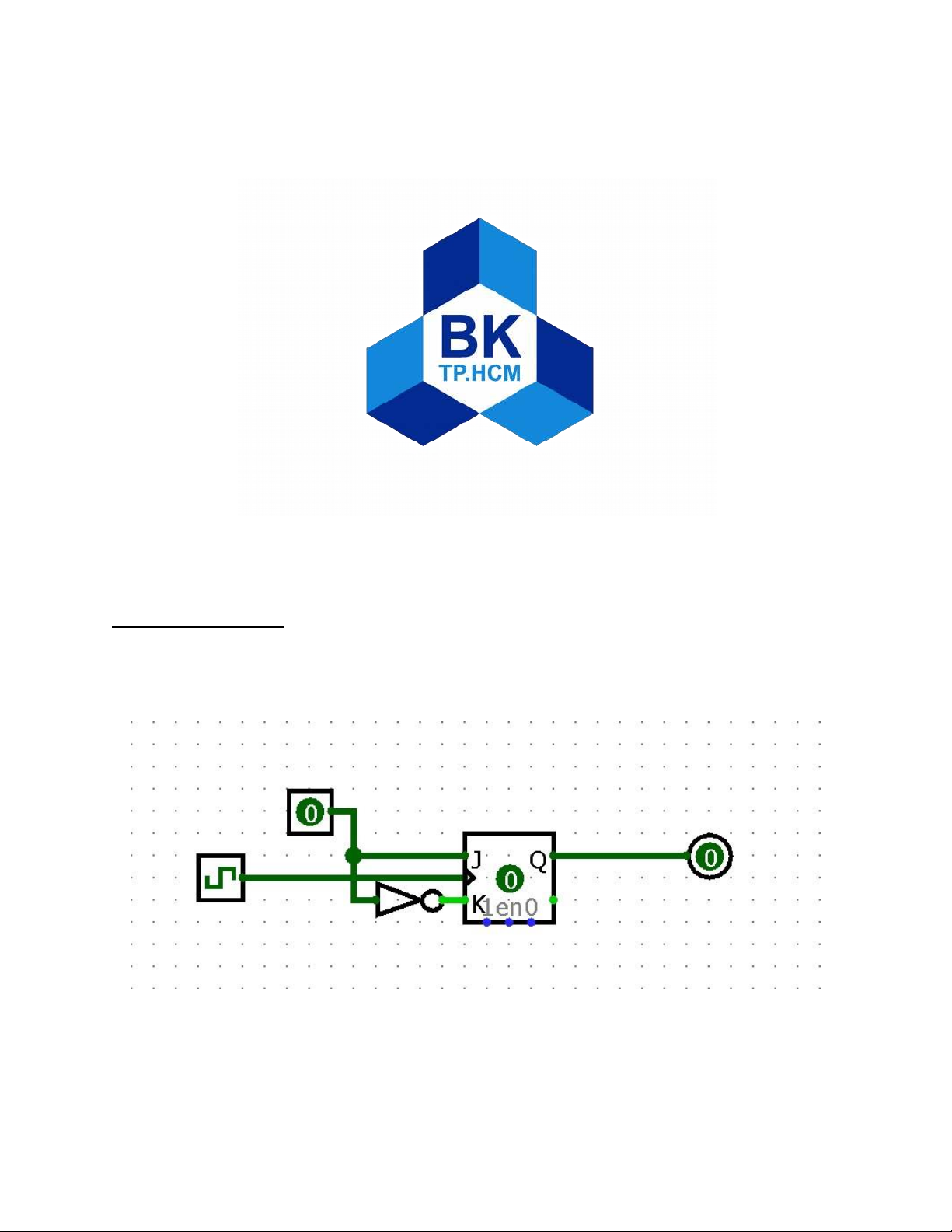
Exercise 2.3.1: Design, simulate and implement a D Flip-flop using J-K Flip-flops (allowed
to use other logic gates if necessary) lOMoARcPSD| 36667950
Based on the truth table of the D flip flop D CLK Q 0 ↑ 0 1 ↑ 1
We can see that the D flip flop is basically a J-K flip flop without the cases J = 0, K = 0 and J =
1, K = 1. Therefore, we can safely assume that J’s input is opposite to K’s input.
To do this, we only need one input, D, in which D is connected to J and a D’ into K of the J-K
flip flop. This ís the truth table of the J-K flip flop: J K CLK Q 0 0 ↑ Q (no change) 1 0 ↑ 1 0 1 ↑ 0 0 0 ↑ Q’ (toggles)
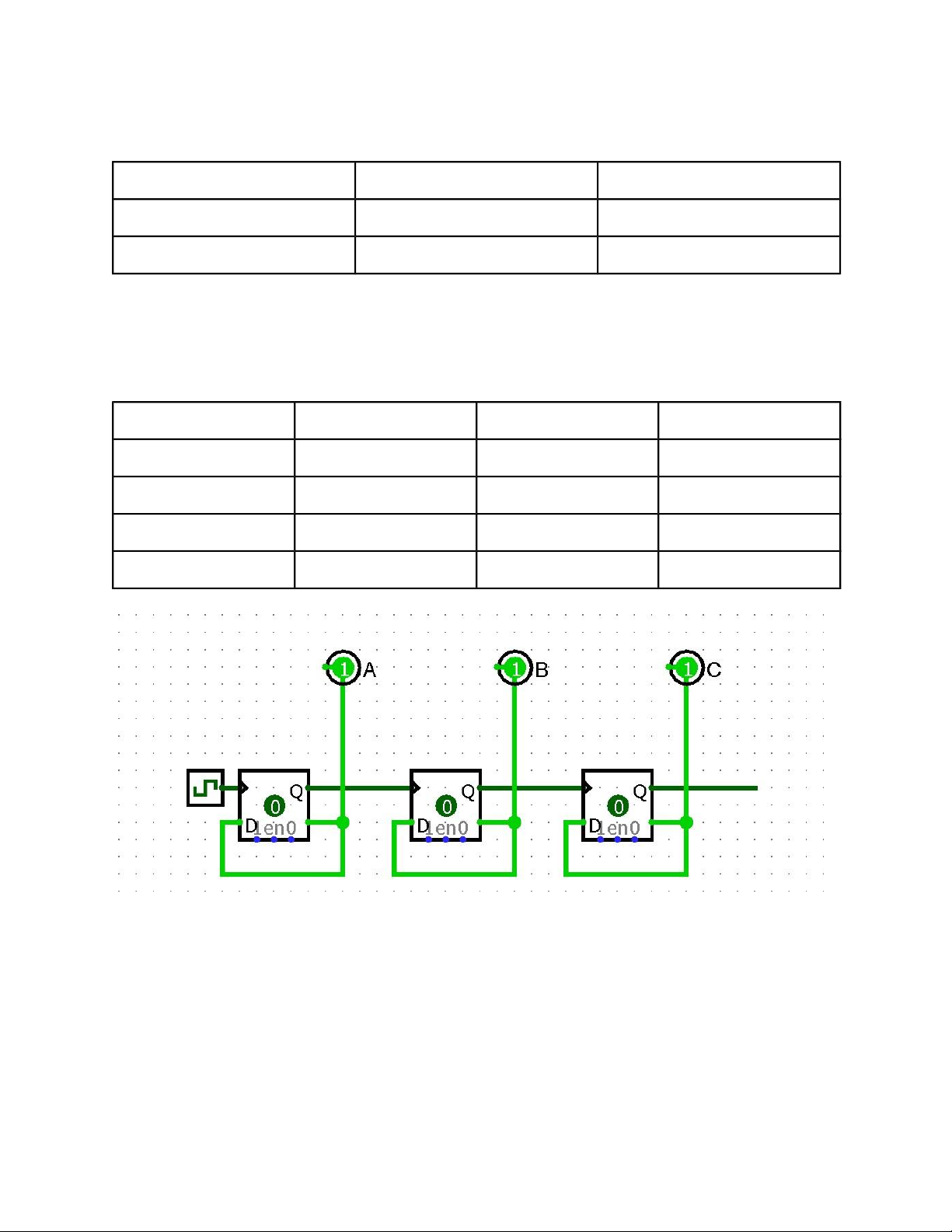
Exercise 2.3.2: Design, simulate and implement the following logic circuit.
After we have implemented the given circuit in to Logisim:
a) The phenomenon that we have observed as we simulate the circuit (tick frequency = 1 lOMoARcPSD| 36667950
Hz) is that, Light A flickers at 0.5 Hz, Light B flickers at 0.25 Hz, Light C flickers at
0.125 (Hz)... → The FREQ of LED 1 is 2 times the FREQ of LED 2 and 4 times than the
FREQ of LED 3 due to the table of change of the LEDs: QC QB QA 0 0 0 0 1 0 0 1 2 0 1 0 3 0 1 1 4 1 0 0 5 1 0 1 6 1 1 0 7 1 1 1
The LEDs are connected in a series of D flip flops wired in a specific way.
We can explain this phenomenon by giving the circuit a closer look.
As the first D flip flop starts at LOW, Light A is static.
When the clock rises and gate Q is at LOW, gate Q’ is HIGH.
D input is wired directly to Q’ and is then altered to HIGH.
Until the next rise, D is finally passed through to Q, which turns to HIGH and Q’ turns to
LOW and then waits for its next turn to pass through D to Q again.
At the circuit output, it requires 2 clock rises for Q to rise once, therefore the circuit
slows the clock down by 2 times.
In conclusion, the circuit is the asynchronous counter from 0 to 7.
b) Based on the observation above, we need 4 D flip flops to build a circuit which outputs a
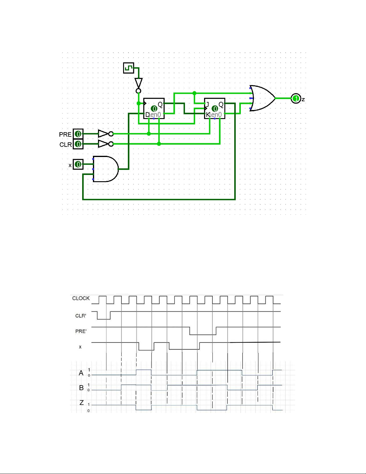
frequency of 16 times less than the clock. (FREQ of D flip flop < 2^n) lOMoARcPSD| 36667950 Exercise 2.3.3 Observation: As we set the clock to 1 Hz.
Output at Z loops in a fixed pattern, HIGH for 3 seconds and then low for 1 second.
b) Based on the waveform, we implement the logic one by one to get our answer: