Báo cáo kết thúc môn học Embeded System bằng tiếng Anh
Báo cáo kết thúc môn học Embeded System bằng tiếng Anh của Đại học Khoa học và Công nghệ Hà Nội với những kiến thức và thông tin bổ ích giúp sinh viên tham khảo, ôn luyện và phục vụ nhu cầu học tập của mình cụ thể là có định hướng ôn tập, nắm vững kiến thức môn học và làm bài tốt trong những bài kiểm tra, bài tiểu luận, bài tập kết thúc học phần, từ đó học tập tốt và có kết quả cao cũng như có thể vận dụng tốt những kiến thức mình đã học vào thực tiễn cuộc sống. Mời bạn đọc đón xem!
Môn: Embedded System 4 tài liệu
Trường: Trường Đại học Khoa học và Công nghệ Hà Nội 85 tài liệu
Tác giả:


Preview text:
lOMoARcPSD| 10435767
I. GENERAL DESIGN OF SMART HOME CONTROL SYSTEM 1. FUNCTION
● From a normal house, we choose a basic design for a 2-members family, including - 1 bedroom - 1 living room + main door - 1 kitchen
● With a selection criteria about smart home in Vietnam, we bring
to the smart home with these conveniences: - Unlock door with passcode
- Auto-curtain system due to the light of the environment
- Temperature and humidity alarm system
- Fire and gas leakage alarm system
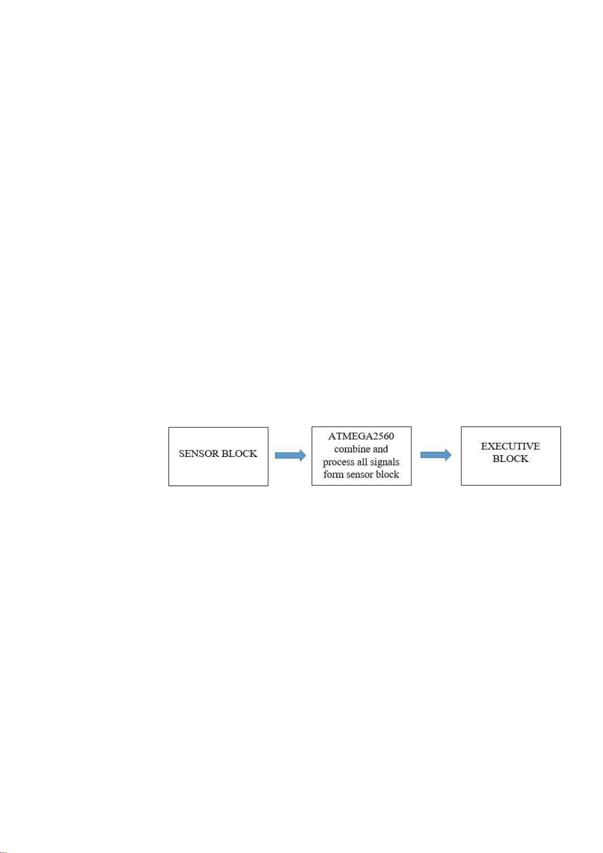
- Auto light, air-conditioner system 2. PRINCIPAL DIAGRAM ● Sensor Block: - Temperature sensor - Humidity sensor - Movement sensor - Gas sensor - Light sensor
● Microprocessor: ATMEGA2560 ● Executive Block: - Main door - Curtains - Light and air-conditioner - Alarm buzzer lOMoARcPSD| 10435767
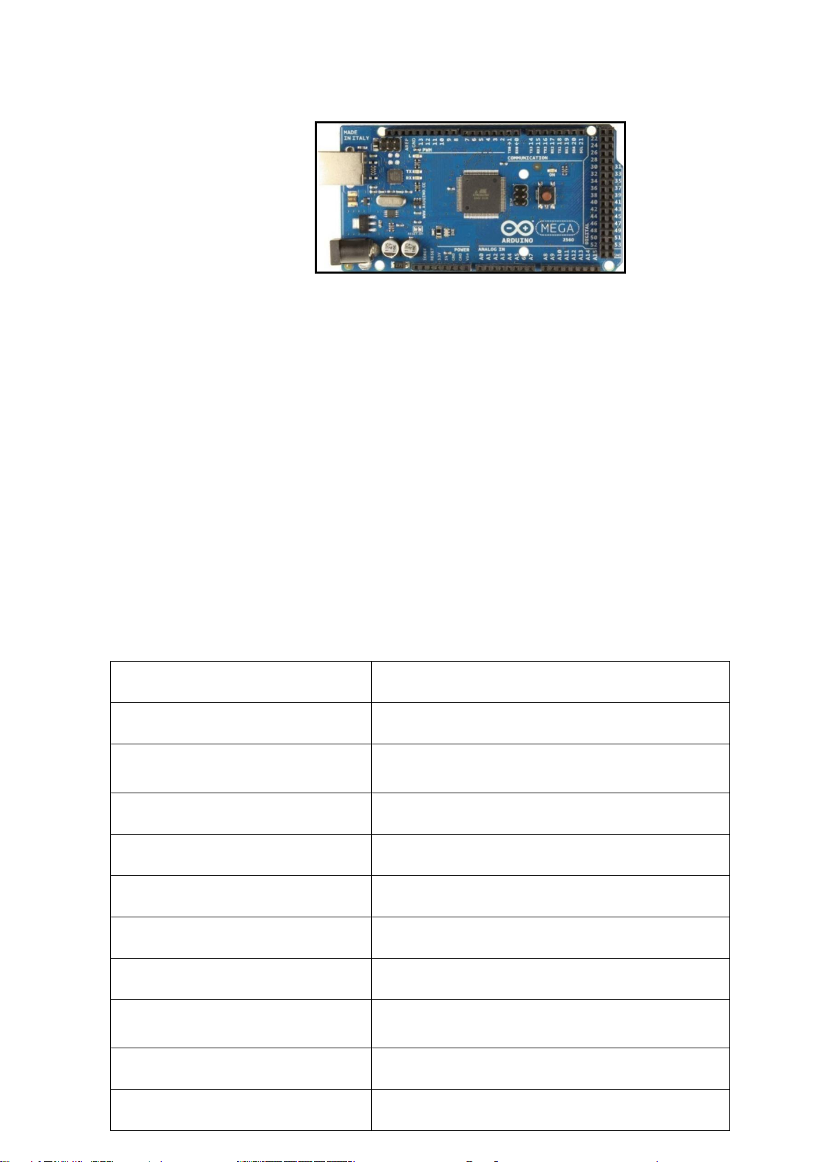
3. INTRODUCTION TO ATMEGA2560 Picture 1: ATMEGA2560 ● General structure
- ATMEGA2560 is a microcontroller board which has 54 digital I/O
pins (of which 15 can be used for pulse width modulation), 16
analog inputs, 4 UARTs (hardware serial ports), a 16 MHz crystal
oscillator, a USB connection, a power jack, an ICSP header, and a
reset button. It contains everything needed to support the
microcontroller; simply connect it to a computer with a USB cable or
power it with a AC-to-DC adapter or battery to get started.
ATMEGA2560 board is compatible with most shields designed for
the Uno and the former boards Duemilanove or Diecimila.
- Arduino Mega2560 is different from all previous microprocessors
because it does not use FTDI control chip to transfer signals from
USB to process. Instead, it uses the programmed ATMEGA16U2 as
a USB converter. ● Signature Microcontroller ATMEGA2560 Operating Voltage 5V Input Voltage (recommended) 7-12V Input Voltage (limits) 6-20V Digital I/O Pins
54 (of which 15 provide PWM output) Analog Input Pins 16 DC Current per I/O Pin 40 mA DC Current for 3.3V Pin 50 mA 256 KB of which 8 KB used by Flash Memory bootloader SRAM 8 KB EEPROM 4 KB lOMoARcPSD| 10435767 Clock Speed 16 MHz ● Diagram of components:
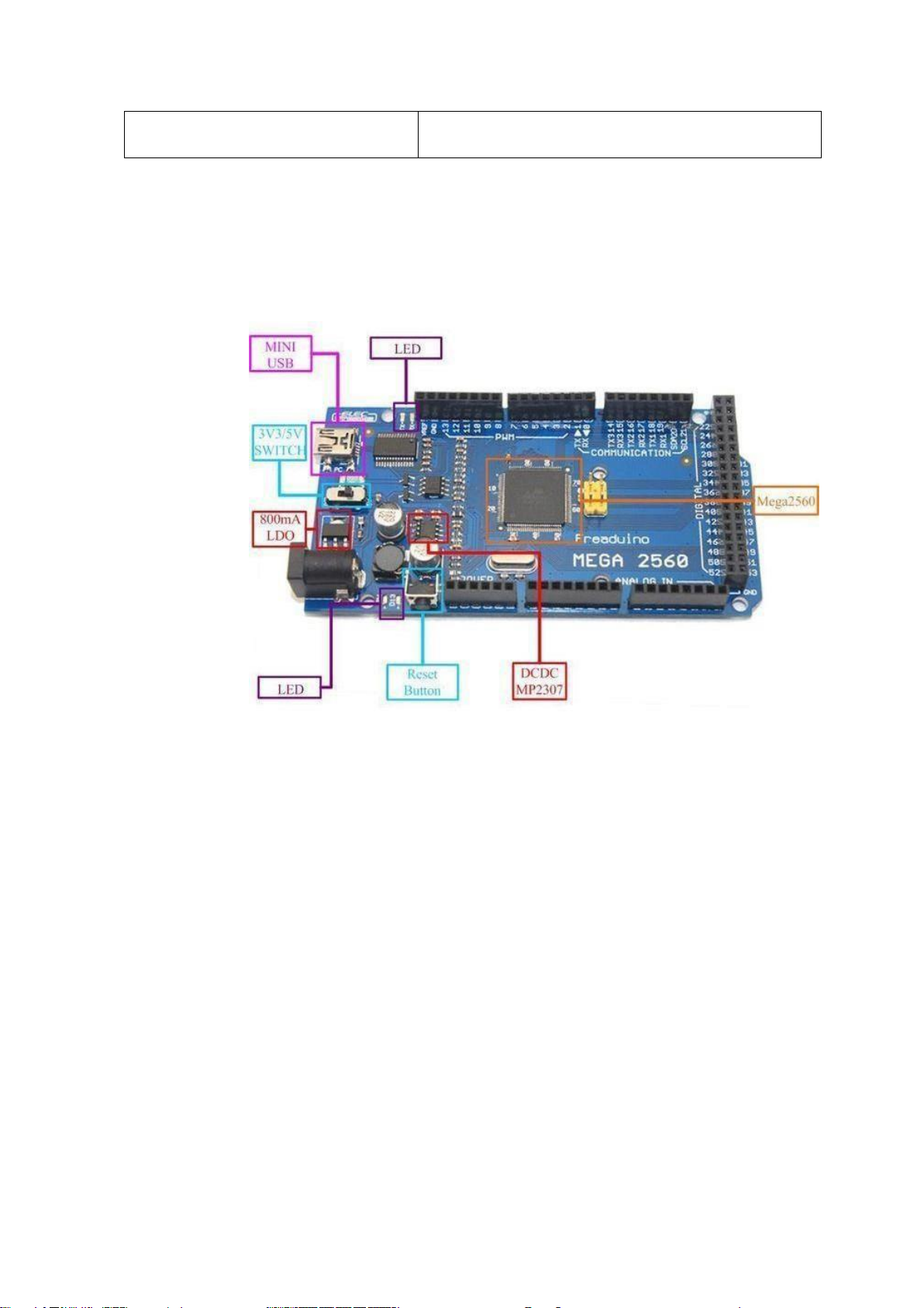
- Arduino Megas has a component diagram like the following pictures (slightly many pins)
Picture 2: Components of ATMEGA2560 - 5 GND pins - 3 pins 5V - 1 pin 3.3v - 1 reset button - 16 analog pins - 4 UART pins
- 54 digital pins of which 15 we can use as PWM - 6 ISP Programming Pins lOMoARcPSD| 10435767
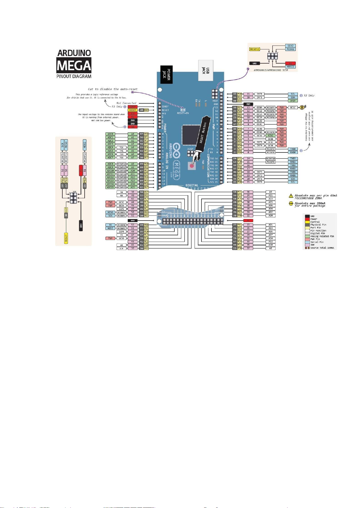
Picture 3: Pin diagram of ATMEGA2560
● Memories and technical values
- ATMEGA2560 has 256KB of flash memories to store program code
(of which 8KB is used for bootloader), 8KB SRAM and 4KB EEPROM
- Each pin on ATMEGA2560 can be used as I/O pins performing at
5V by configuring their register bits. Each pin can provide or receive
up to 40mA and have a resistance of 20-50KΩ.
- Also there are some other pins have special function:
+ External interrupts: 2(-0), 3(-1), 18 (-5), 19(-4), 20(-3), 21(-2) + Serial 0: 0 (RX) and 1 (TX)
+ Serial 1: 19 (RX) and 18 (TX)
+ Serial 2: 17 (RX) and 16 (TX)
+ Serial 3: 15 (RX) and 14 (TX)
+ PWM: 2-13 and 44-46 (Producing 8-bit PWM output by using Timer/Counter)
+ SPI: 50 (MISO), 51 (MOSI), 52 (SCK), 53 (SS). + LED: 13 + TWI: 20 (SDA) and 21 (SCL) lOMoARcPSD| 10435767
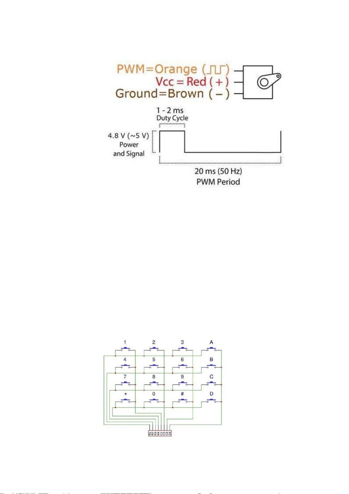
4. INTRODUCTION TO SERVO MOTOR SG90
Picture 4: Pin diagram of servo motor SG90 ●
Servo motor SG90 including 3 pins: -
Pulse Width Modulation PWM (orange) -
VCC 5V (red) - Ground (brown) ● Main values: - Twist moment: 1.8kg/cm - Working speed: 600C in 0.1s -
Working voltage: 4.8V (~5V) - Working temperature: 00C
– 550C ● Application in system: - Auto curtains - Open/Close the main door
5. INTRODUCTION TO KEYPAD
● The microcontroller knows whichever button is pressed by
controlling the row and column pins connected to the buttons.
● The button detection process: lOMoARcPSD| 10435767
- Column pins are configured as inputs with pull-up
resistors to stay HIGH when no button is pressed.
- Row pins are configured as outputs that stay LOW at the beginning.
- When a button is pressed, the column corresponding to it
will go LOW due to the connection with the row pin, and
the microcontroller detects this pin.
- After, each row pin is programmed to go HIGH, and
whichever row pin that pulls the column pin above HIGH
is the row of the button pressed.
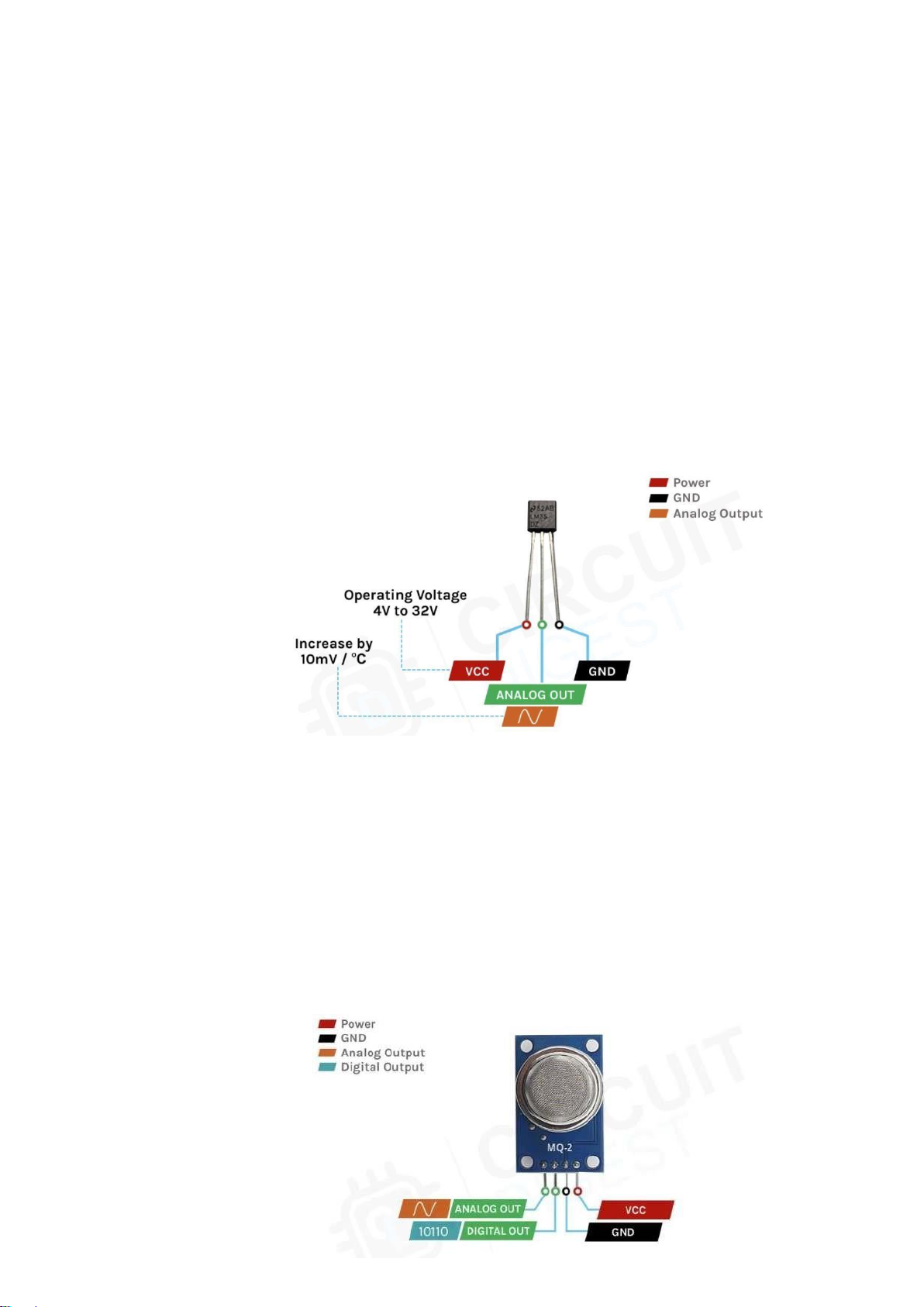
6. INTRODUCTION TO TEMPERATURE SENSOR LM35
(Picture taken from circuitdigest.com)
• The temperature sensor LM35 works by measuring the ambient heat and
converting it to voltage value that is pushed out its analog output pin.
• The general equation for temperature to voltage of LM35 is:
Temperature (0C) = Voltage x 100.
• This voltage can be read by the microcontroller via its ADC register function.
7. INTRODUCTION TO GAS SENSOR MQ-2 lOMoARcPSD| 10435767
(Picture taken from circuitdigest.com)
• This gas sensor MQ-2 can detect and measure the level of gas in the
environment and convert it to voltage signal, which is pushed out via its analog output pin.
• In our project, we only make use of the analog output pin.
• This voltage can be read by the microcontroller via its ADC register function.
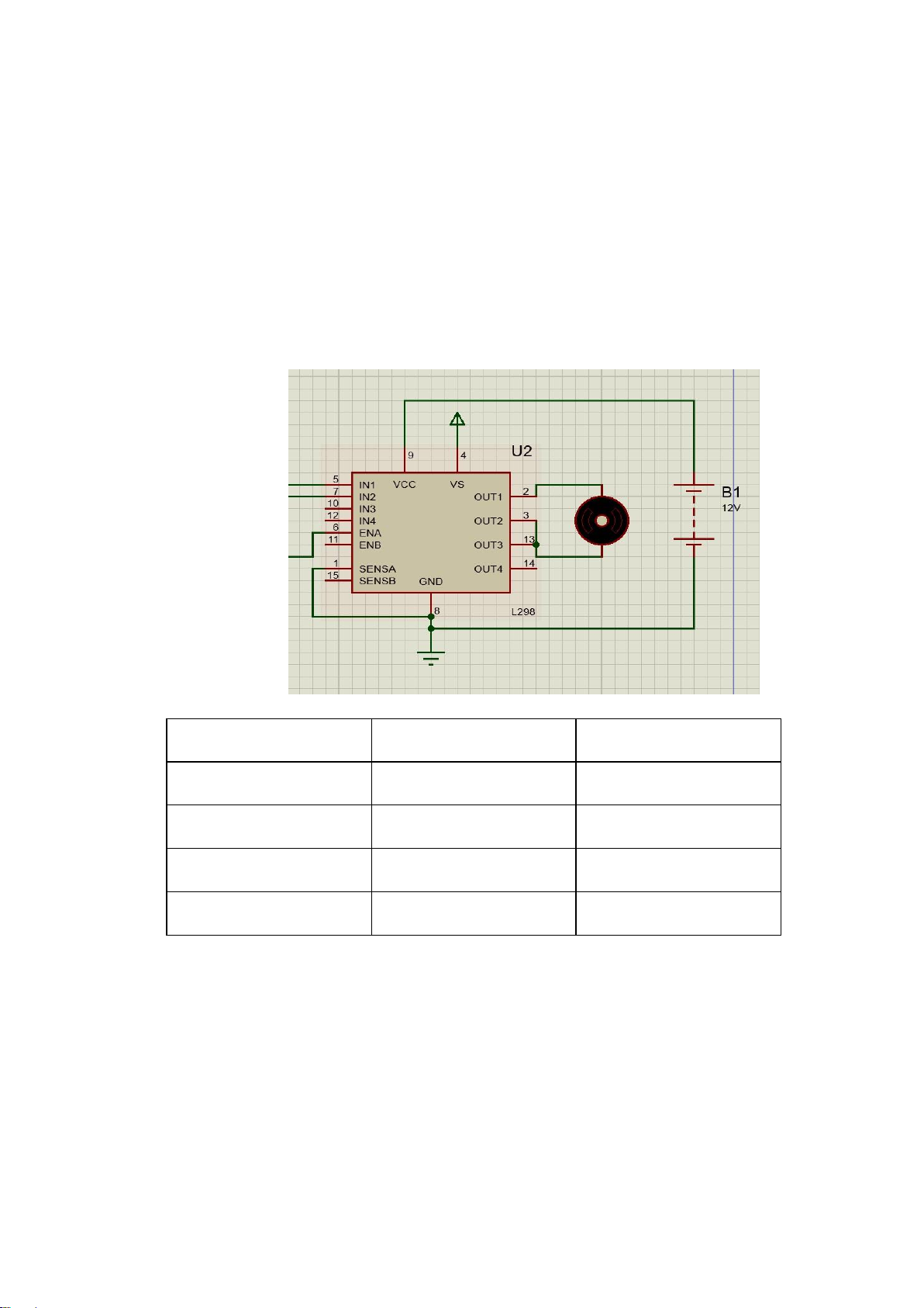
8. INTRODUCTION TO L298 AND DC MOTOR IN1 IN2 DC MOTOR LOW LOW Float HIGH LOW Clockwise LOW HIGH Counter-clockwise HIGH HIGH Brake
• In addition to the above table, the speed of the DC motor can also be
controlled by PWM pulses going in the ENA pin. The larger the duty cycle
of the PWM is, the faster the rotation of the motor becomes.
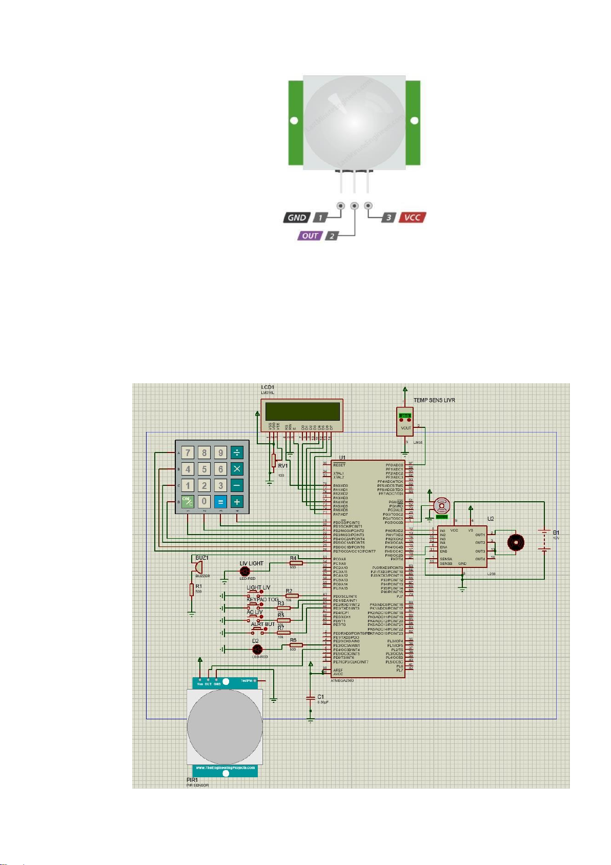
9. INTRODUCTION TO PIR SENSOR lOMoARcPSD| 10435767
• The PIR sensor works on a simple principle: it outputs HIGH when motion is
detected and goes LOW when no motion is detected.
II. MODULE IN USED FOR EACH FEATURE AND THEIR FUNCTIONS
1. Living room and main door a. Schematic b. Function
● Automatic door control using servo and keypad. lOMoARcPSD| 10435767
● Buttons to control living room light, air conditioner, and alarm buzzer.
● Temperature sensing and automatic air conditioner control based on temperature.
● Automatic light control by motion sensing. c. Execution process
● 1 servo motor will unlock/lock the door after receiving the
correct inputs from the keypad.
● 1 simple PIR sensor located at the door will turn on the light
when receiving the signal if anyone comes in
● 1 simple DC motor with L298 controls the air-conditioner
turning on/off and speed based on temperature.
● 3 simple buttons in the living room to toggle on/off the light in
the living room, the air-conditioner, the alarm buzzer
● 1 small keypad at the front door to prevent unwanted guests. The
keypad can be toggled on/off by a button. The password for the
button is a 9-number sequence: 1, 4, 7, 3, 6, 9, 2, 5, 8, and ON/C
to confirm. If the password is wrong 3 times, the alarm will go off.
● 1 LCD to display the temperature in the room and the password
inputted when the keypad is on.
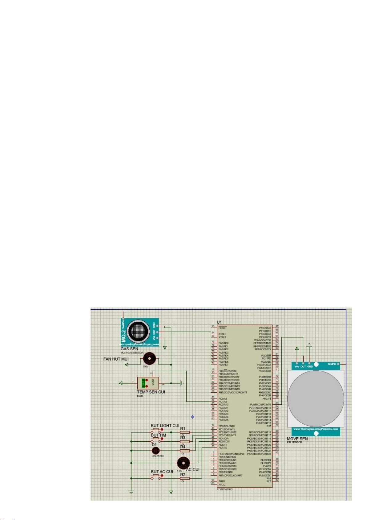
2. Kitchen a. Schematic lOMoARcPSD| 10435767 b. Function
● Warn when there is an intruder through the window.
● Alarm when the temperature rises above the specified level.
● Alarm when the gas concentration exceeds the specified level.
● Automatically increase fan speed with DC motor when the gas
concentration increases over the specified level. c. Execution process
● The motion sensor placed near the window has the function of
sending a signal to the circuit board to turn it on siren when intrusion is detected.
● Temperature sensor LM35 and gas sensor MQ2: siren will
sound when parameter temperature from sensor LM35 and gas
concentration reading from sensor MQ2 exceeds specified level.
● Additionally, the DC motor of the fan will be activated to
increase the speed of the fan.
3. Bedroom a. Schematic b. Function
● Automatically open/close the curtain due to the light of the environment lOMoARcPSD| 10435767
● Inform the temperature àn humidity through LCD screen
● Automatically speed up the air-conditioner when the temperature is over the limit c. Execution process
● 1 servo motor and a gear system to open/close the curtain and a
light sensor to control the motor when the sky is bright or dark ● 1
simple DC motor connect to the fan to control the speed III. CODE
1. LIVING ROOM & FRONT DOOR
* LIVING_ROOMnFRONT_DOOR.c *
* Created: 2/12/2023 10:47:32 AM * Author : Long */
#define F_CPU 8000000UL #define ADC_VREF_TYPE ((0< #include #include #include #include #include #include
int i = 0; int j = 0; int celsius; int voltage; int correct_pass = 0; int wrong_pass = 0; char key[9];
char password[] = {1, 4, 7, 3, 6, 9, 2, 5, 8};
char state = 0; char light_state = 0; char
ac_state = 0; char alarm_state = 0; #define LCD_Dir DDRA
/* Define LCD data port direction */ #define LCD_Port PORTA
/* Define LCD data port */ #define RS PA0
/* Define Register Select pin */ #define EN PA1
/* Define Enable signal pin */
void LCD_Command( unsigned char cmnd ) {
LCD_Port = (LCD_Port & 0x0F) | (cmnd & 0xF0); /* sending upper nibble */ LCD_Port &= ~ (1<
/* RS=0, command reg. */
LCD_Port |= (1</* Enable pulse */ _delay_us(1); LCD_Port &= ~ (1<
_delay_us(200); lOMoARcPSD| 10435767
LCD_Port = (LCD_Port & 0x0F) | (cmnd << 4); /* sending lower nibble */ LCD_Port |= (1< _delay_us(1); LCD_Port &= ~ (1< _delay_ms(2); }
void LCD_Char( unsigned char data ) {
LCD_Port = (LCD_Port & 0x0F) | (data & 0xF0); /* sending upper nibble */
LCD_Port |= (1</* RS=1, data reg. */ LCD_Port|= (1< _delay_us(1); LCD_Port &= ~ (1<
_delay_us(200);
LCD_Port = (LCD_Port & 0x0F) | (data << 4); /* sending lower nibble */ LCD_Port |= (1< _delay_us(1); LCD_Port &= ~ (1< _delay_ms(2); } void LCD_init (void)
/* LCD Initialize function */ { _delay_ms(20);
/* LCD Power ON delay always >15ms */ LCD_Command(0x02);
/* send for 4 bit initialization of LCD */
LCD_Command(0x28); /* 2 line, 5*7 matrix in 4-bit mode */
LCD_Command(0x0c); /* Display on cursor off*/
LCD_Command(0x06); /* Increment cursor (shift cursor to right)*/
LCD_Command(0x01); /* Clear display screen*/ _delay_ms(2); } void LCD_String (char *str)
/* Send string to LCD function */ { int i; for(i=0;str[i]!=0;i++)
/* Send each char of string till the NULL */ { LCD_Char (str[i]); } }
void LCD_String_xy (char row, char pos, char *str)
/* Send string to LCD with xy position */ {
if (row == 0 && pos<16)
LCD_Command((pos & 0x0F)|0x80); /* Command of first row and required position<16 */
else if (row == 1 && pos<16)
LCD_Command((pos & 0x0F)|0xC0); /* Command of first row and required position<16 */ LCD_String(str);
/* Call LCD string function */ } void LCD_Clear() { LCD_Command (0x01); /* Clear display */ _delay_ms(2); LCD_Command (0x80);
/* Cursor at home position */ } lOMoARcPSD| 10435767 //functions //front door alarm void ALARM(void){ if(alarm_state){ PORTC |= 1< }else{ PORTC &= ~(1< } }
//motion turns on light void
motion_sens(void){ if((PINE & (1<(1< PORTE |= (1< }else PORTE &= ~(1< }
//door control using servo motor void door_unlock(void){
for(i = 16; i>=6; i--){ OCR0B = i;
_delay_ms(100); } } void door_lock(void){
for(i = 6; i<=16; i++){ OCR0B = i;
_delay_ms(100); } }
//keypad password matching to unlock and open door
void match_password(void){ for(i = 0; i <= 8; i++){
if(key[i] == password[i]){ correct_pass++; } }
if(correct_pass == 8){ correct_pass = 0; wrong_pass = 0; door_unlock(); LCD_Clear();
LCD_String("Door Unlocked!");
_delay_ms(10000);
door_lock();//door will close after 10s }else{ correct_pass = 0; wrong_pass++; LCD_Clear();
LCD_String("Wrong Pass!");
if(wrong_pass > 3){ ALARM(); wrong_pass = 0; } } }
//getting key pressed void key_input(void){ lOMoARcPSD| 10435767 LCD_Clear(); if(state){
LCD_String_xy(0, 0, "Enter Pass: "); } while(state){ switch(PINB){ case 0x07:
for(i = 7; i>=4; i--){ PORTB |= (1< if((PINB & (1< switch(i){ case 7: key[j] = 7; j++; break; case 6: key[j] = 4; j++; break; case 5: key[j] = 1; j++; break; case 4: key[j] = 15; j++; break; } } PORTB &= ~(1< }
_delay_ms(100); break; case 0x0b:
for(i = 7; i>=4; i--){ PORTB |= (1< if((PINB & (1< switch(i){ case 7: key[j] = 8; j++; break; case 6: key[j] = 5; j++; break; case 5: key[j] = 2; j++; break; case 4: key[j] = 0; j++; break; } } PORTB &= ~(1< }
_delay_ms(100); break; case 0x0d:
for(i = 7; i>=4; i--){ PORTB |= (1< if((PINB & (1< switch(i){ case 7: key[j] = 9; lOMoARcPSD| 10435767 j++; break; case 6: key[j] = 6; j++; break; case 5: key[j] = 3; j++; break; case 4: key[j] = 14; j++; break; } } PORTB &= ~(1< } _delay_ms(100); break; case 0x0e:
for(i = 3; i>=0; i--){ PORTB |= (1< if((PINB & (1< switch(i){ case 3: key[j] = 10; j++; break; case 2: key[j] = 11; j++; break; case 1: key[j] = 12; j++; break; case 0: key[j] = 13; j++; break; } } PORTB &= ~(1< }
_delay_ms(100); break; default: break; } switch(key[j]){ case 0:
LCD_String_xy(1, j, "0"); break; case 1:
LCD_String_xy(1, j, "1"); break; case 2:
LCD_String_xy(1, j, "2"); break; case 3:
LCD_String_xy(1, j, "3"); break; case 4: lOMoARcPSD| 10435767
LCD_String_xy(1, j, "4"); break; case 5:
LCD_String_xy(1, j, "5"); break; case 6:
LCD_String_xy(1, j, "6"); break; case 7:
LCD_String_xy(1, j, "7"); break; case 8:
LCD_String_xy(1, j, "8"); break; case 9:
LCD_String_xy(1, j, "9"); break; case 10:
LCD_String_xy(1, j, "/"); break; case 11:
LCD_String_xy(1, j, "X"); break; case 12:
LCD_String_xy(1, j, "-"); break; case 13:
LCD_String_xy(1, j, "+"); break; case 14:
LCD_String_xy(1, j, "="); break; default: break; } if(j == 8){ j = 0; state = 0; } } }
//air_con control via DC motor void air_con(char x){ if(x){ PORTH |= 1< PORTH &= ~(1< }else{ PORTH |= (1< PORTH |= (1< } }
// Read the AD conversion result
unsigned int read_adc(unsigned char adc_input) {
ADMUX=(adc_input & 0x1f) | ADC_VREF_TYPE;
if (adc_input & 0x20) ADCSRB|=(1< else ADCSRB&=~(1<
// Delay needed for the stabilization of the ADC input voltage _delay_us(10);
// Start the AD conversion ADCSRA|=(1<
// Wait for the AD conversion to complete while ((ADCSRA & (1<
ADCSRA|=(1< return ADCW; lOMoARcPSD| 10435767 }
//Temperature sensor void
temperature_sens(void){ voltage = read_adc(0) * 5/1023; celsius = voltage * 100; if(read_adc(0) >= 100){ //turn on air-con OCR2B = 0x6C; ac_state = 1; alarm_state = 1;
}else if(read_adc(0) >= 50 && read_adc(0) < 100){ OCR2B = 0x4E; ac_state = 1; }else{ ac_state = 0; } }
//micro-controller configuration
//clock initialization lOMoARcPSD| 10435767 void CLK_init(void){
// Crystal Oscillator division factor: 1 CLKPR=(1< CLKPR=(0< } //ADC initialization void ADC_init(){ // ADC initialization
// ADC Clock frequency: 1000.000 kHz
// ADC Voltage Reference: AREF pin
// ADC Auto Trigger Source: ADC Stopped
// Digital input buffers on ADC0: On, ADC1: On, ADC2: On, ADC3: On
// ADC4: On, ADC5: On, ADC6: On, ADC7: On DIDR0=(0<(0<
// Digital input buffers on ADC8: On, ADC9: On, ADC10: On, ADC11: On
// ADC12: On, ADC13: On, ADC14: On, ADC15: On DIDR2=(0<(0< ADMUX=ADC_VREF_TYPE; ADCSRA=(1<(1< ADCSRB=(0< } //Port initialization void IO_init(void){
//Port A initialization
//Function: Bit7=Out Bit6=Out Bit5=Out Bit4=Out Bit3=Out Bit2=Out Bit1=Out Bit0=Out DDRA=(1<
//State: Bit7=0 Bit6=0 Bit5=0 Bit4=0 Bit3=0 Bit2=0 Bit1=0 Bit0=0 PORTA=(0<
// Port B initialization
// Function: Bit7=Out Bit6=Out Bit5=Out Bit4=Out Bit3=In Bit2=In Bit1=In Bit0=In DDRB=(1<
// State: Bit7=0 Bit6=0 Bit5=0 Bit4=0 Bit3=P Bit2=P Bit1=P Bit0=P PORTB=(0<
// Port C initialization
// Function: Bit7=In Bit6=In Bit5=In Bit4=In Bit3=In Bit2=In Bit1=Out Bit0=Out DDRC=(0<
// State: Bit7=T Bit6=T Bit5=T Bit4=T Bit3=T Bit2=T Bit1=0 Bit0=0 PORTC=(0<
// Port D initialization
// Function: Bit7=In Bit6=In Bit5=In Bit4=In Bit3=In Bit2=In Bit1=In Bit0=In DDRD=(0<
// State: Bit7=T Bit6=T Bit5=T Bit4=T Bit3=P Bit2=P Bit1=P Bit0=P PORTD=(0<
// Port E initialization
// Function: Bit7=In Bit6=In Bit5=In Bit4=In Bit3=Out Bit2=In Bit1=In Bit0=In DDRE=(0<
// State: Bit7=T Bit6=T Bit5=T Bit4=T Bit3=T Bit2=T Bit1=T Bit0=T PORTE=(0<
// Port G initialization
// Function: Bit5=Out Bit4=In Bit3=In Bit2=In Bit1=In Bit0=In DDRG=(1< lOMoARcPSD| 10435767
// State: Bit5=0 Bit4=T Bit3=T Bit2=T Bit1=T Bit0=T PORTG=(0<
// Port H initialization
// Function: Bit7=In Bit6=In Bit5=In Bit4=In Bit3=In Bit2=In Bit1=Out Bit0=Out DDRH=(0<
// State: Bit7=T Bit6=T Bit5=T Bit4=T Bit3=T Bit2=T Bit1=0 Bit0=0 PORTH=(0< }
//Timer_Counter initialization void TC_init(void){
// Timer/Counter 0 initialization
// Clock source: System Clock
// Clock value: 7.813 kHz
// Mode: Fast PWM top=OCR0A
// OC0A output: Disconnected // OC0B output: Non-Inverted PWM
// Timer Period: 19.968 ms // Output Pulse(s):
// OC0B Period: 19.968 ms Width: 0.77295 ms TCCR0A=(0< TCCR0B=(1< TCNT0=0x00; OCR0A=0x9B; OCR0B=0x06;
// Timer/Counter 2 initialization
// Clock source: System Clock
// Clock value: 7.813 kHz
// Mode: Fast PWM top=OCR2A
// OC2A output: Disconnected // OC2B output: Non-Inverted PWM
// Timer Period: 20 ms // Output Pulse(s):
// OC2B Period: 20 ms Width: 10 ms ASSR=(0< TCCR2A=(0< TCCR2B=(1< TCNT2=0x00; OCR2A=0x9B; OCR2B=0x4E; }
//INT0 interrupt service routine handler
//turn on living room light ISR(INT0_vect){ _delay_ms(10); if(light_state){ PORTC &= ~(1< light_state = 0; }else{ PORTC |= 1< light_state = 1; } }
//INT1 interrupt service routine handler
//used to toggle keypad inputting ISR(INT1_vect){ _delay_ms(10); if(state){ lOMoARcPSD| 10435767 state = 0; }else{ state = 1; } }
//INT2 interrupt service routine handler
//used to turn on/off air con ISR(INT2_vect){ _delay_ms(10); if(ac_state){ ac_state = 0; }else{ ac_state = 1; } }
//INT3 interrupt service routine handler
//used to sound the alert ISR(INT3_vect){ _delay_ms(10); if(alarm_state){ alarm_state = 0; }else{ alarm_state = 1; } }
//INT4 interrupt service routine handler
//used to detect motion via PIR ISR(INT4_vect){ _delay_ms(10); motion_sens(); }
//Interrupt initialization void INTERRUPT_init(void){
// External Interrupt(s) initialization // INT0: On
// INT0 Mode: Falling Edge // INT1: On
// INT1 Mode: Falling Edge // INT2: On
// INT2 Mode: Falling Edge // INT3: On
// INT3 Mode: Falling Edge // INT4: On
// INT4 Mode: Any change EICRA=(1<(1< EICRB=(0<(0< EIMSK=(0<(1< EIFR=(0<| (1< sei(); } //MAIN int main(void) { char temperature[3]; lOMoARcPSD| 10435767
/* Replace with your application code */ CLK_init(); LCD_init(); ADC_init(); IO_init(); TC_init(); INTERRUPT_init(); LCD_Clear(); while (1) { temperature_sens(); ALARM(); key_input(); air_con(ac_state);
itoa(celsius, temperature, 0); _delay_ms(10);
LCD_String_xy(0, 0, "Temperature: ");
LCD_String_xy(1, 0, temperature); } } 2. KITCHEN CODE
#define F_CPU 8000000UL #include #include #include
#define ADC_VREF_TYPE 0x40
#define LM35_TEMPERATURE_CHANNEL 0x00
#define MQ2_GAS_CHANNEL 0x01
#define THRESHOLD_TEMPERATURE 28
#define THRESHOLD_GAS 500
#define BUZZER_PORT PORTB
#define BUZZER_DDR DDRB lOMoARcPSD| 10435767 #define BUZZER_PIN PB0
#define LCD_Dir DDRA /* Define LCD data port direction */ #define LCD_Port PORTA /*
Define LCD data port */ #define RS PA0
/* Define Register Select pin */ #define EN PA1
/* Define Enable signal pin */
void LCD_Command( unsigned char cmnd ) {
LCD_Port = (LCD_Port & 0x0F) | (cmnd & 0xF0); /* sending upper nibble */ LCD_Port &= ~ (1<
/* RS=0, command reg. */ LCD_Port |= (1< /* Enable pulse */
_delay_us(1); LCD_Port &= ~ (1<
_delay_us(200);
LCD_Port = (LCD_Port & 0x0F) | (cmnd << 4); /* sending lower nibble */ LCD_Port |= (1<
_delay_us(1); LCD_Port &= ~ (1<
_delay_ms(2); }
void LCD_Char( unsigned char data ) {
LCD_Port = (LCD_Port & 0x0F) | (data & 0xF0); /* sending upper nibble */ LCD_Port |= (1< /* RS=1, data reg. */ LCD_Port|= (1<
_delay_us(1); LCD_Port &= ~ (1<
_delay_us(200); lOMoARcPSD| 10435767
LCD_Port = (LCD_Port & 0x0F) | (data << 4); /* sending lower nibble */ LCD_Port |= (1<
_delay_us(1); LCD_Port &= ~ (1<
_delay_ms(2); } void LCD_init (void)
/* LCD Initialize function */ {
_delay_ms(20);
/* LCD Power ON delay always >15ms */ LCD_Command(0x02);
/* send for 4 bit initialization of LCD */ LCD_Command(0x28);
/* 2 line, 5*7 matrix in 4-bit mode */ LCD_Command(0x0c);
/* Display on cursor off*/ LCD_Command(0x06);
/* Increment cursor (shift cursor to right)*/ LCD_Command(0x01);
/* Clear display screen*/
_delay_ms(2); }
void LCD_String (char *str)
/* Send string to LCD function */ { int i;
for(i=0;str[i]!=0;i++)
/* Send each char of string till the NULL */ { LCD_Char (str[i]); } }
void LCD_String_xy (char row, char pos, char *str) /* Send string to LCD with xy position */ { lOMoARcPSD| 10435767
if (row == 0 && pos<16)
LCD_Command((pos & 0x0F)|0x80); /* Command of first row and required position<16 */ else if
(row == 1 && pos<16)
LCD_Command((pos & 0x0F)|0xC0); /* Command of first row and required position<16 */
LCD_String(str); /* Call LCD string function */ } void LCD_Clear() {
LCD_Command (0x01); /* Clear display */
_delay_ms(2);
LCD_Command (0x80); /* Cursor at home position */ } void adc_init(void) {
ADMUX = ADC_VREF_TYPE & 0xff;
ADCSRA = (1 << ADEN) | (1 << ADPS2) | (1 << ADPS1) | (1 << ADPS0); }
uint16_t adc_read(uint8_t channel) {
ADMUX = (ADMUX & 0xf0) | (channel & 0x0f);
ADCSRA |= (1 << ADSC); while (ADCSRA & (1 << ADSC)); return ADC; }
void display_temperature(double temperature) { char buffer[16];
sprintf(buffer, "Temperature: %.2f C", temperature); lOMoARcPSD| 10435767 LCD_Clear(); LCD_String(buffer); }
void warn_gas_sensor(uint16_t gas) {
if (gas > THRESHOLD_GAS) {
BUZZER_PORT |= (1 << BUZZER_PIN); LCD_Clear();
LCD_String("Warning: Gas");
_delay_ms(1000);
BUZZER_PORT &= ~(1 << BUZZER_PIN); } } int main(void) { adc_init(); LCD_init();
BUZZER_DDR |= (1 << BUZZER_PIN); while (1) {
double temperature_voltage = adc_read(LM35_TEMPERATURE_CHANNEL) * 5.0 / 1024;
double temperature = temperature_voltage / 0.01; display_temperature(temperature);
if (temperature > THRESHOLD_TEMPERATURE) {
BUZZER_PORT |= (1 << BUZZER_PIN); LCD_Clear();
LCD_String("Warning: Gas");
_delay_ms(1000); lOMoARcPSD| 10435767
BUZZER_PORT &= ~(1 << BUZZER_PIN); }
uint16_t gas = adc_read(MQ2_GAS_CHANNEL); warn_gas_sensor(gas);
_delay_ms(500); } return 0; } 3. BEDROOM CODE
#define F_CPU 8000000UL #include #include #include
#include "Servo/ServoTimers.h"
#define ADC_VREF_TYPE 0x40
#define LM35_TEMPERATURE_CHANNEL 0x00
#define LIGHT_SENSOR_CHANNEL 0x01
#define THRESHOLD_TEMPERATURE 28
#define THRESHOLD_LIGHT 300 #define AC_PORT PORTB #define AC_DDR DDRB #define AC_PIN PB0 lOMoARcPSD| 10435767 #define SERVO_PIN PB1 #define LCD_Dir DDRA
/* Define LCD data port direction */
#define LCD_Port PORTA
/* Define LCD data port */ #define RS PA0
/* Define Register Select pin */ #define EN PA1
/* Define Enable signal pin */
void LCD_Command( unsigned char cmnd ) {
LCD_Port = (LCD_Port & 0x0F) | (cmnd & 0xF0); /* sending upper nibble */ LCD_Port &= ~ (1<
/* RS=0, command reg. */ LCD_Port |= (1< /* Enable pulse */
_delay_us(1); LCD_Port &= ~ (1<
_delay_us(200);
LCD_Port = (LCD_Port & 0x0F) | (cmnd << 4); /* sending lower nibble */ LCD_Port |= (1<
_delay_us(1); LCD_Port &= ~ (1<
_delay_ms(2); }
void LCD_Char( unsigned char data ) {
LCD_Port = (LCD_Port & 0x0F) | (data & 0xF0); /* sending upper nibble */ LCD_Port |= (1< /* RS=1, data reg. */ LCD_Port|= (1<
_delay_us(1); lOMoARcPSD| 10435767 LCD_Port &= ~ (1<
_delay_us(200);
LCD_Port = (LCD_Port & 0x0F) | (data << 4); /* sending lower nibble */ LCD_Port |= (1<
_delay_us(1); LCD_Port &= ~ (1<
_delay_ms(2); } void LCD_init (void)
/* LCD Initialize function */ {
_delay_ms(20);
/* LCD Power ON delay always >15ms */ LCD_Command(0x02);
/* send for 4 bit initialization of LCD */ LCD_Command(0x28);
/* 2 line, 5*7 matrix in 4-bit mode */ LCD_Command(0x0c);
/* Display on cursor off*/ LCD_Command(0x06);
/* Increment cursor (shift cursor to right)*/ LCD_Command(0x01);
/* Clear display screen*/
_delay_ms(2); }
void LCD_String (char *str)
/* Send string to LCD function */ { int i;
for(i=0;str[i]!=0;i++)
/* Send each char of string till the NULL */ { LCD_Char (str[i]); } lOMoARcPSD| 10435767 }
void LCD_String_xy (char row, char pos, char *str) /* Send string to LCD with xy position */ {
if (row == 0 && pos<16)
LCD_Command((pos & 0x0F)|0x80); /* Command of first row and required position<16 */ else if
(row == 1 && pos<16)
LCD_Command((pos & 0x0F)|0xC0); /* Command of first row and required position<16 */
LCD_String(str); /* Call LCD string function */ } void LCD_Clear() {
LCD_Command (0x01); /* Clear display */
_delay_ms(2);
LCD_Command (0x80); /* Cursor at home position */ } void adc_init(void) {
ADMUX = ADC_VREF_TYPE & 0xff;
ADCSRA = (1 << ADEN) | (1 << ADPS2) | (1 << ADPS1) | (1 << ADPS0); }
uint16_t adc_read(uint8_t channel) {
ADMUX = (ADMUX & 0xf0) | (channel & 0x0f);
ADCSRA |= (1 << ADSC); while (ADCSRA & (1 << ADSC)); return ADC; } lOMoARcPSD| 10435767
void display_temperature(double temperature) { char buffer[16];
sprintf(buffer, "Temperature: %.2f C", temperature); LCD_Clear(); LCD_String(buffer); }
void control_air_conditioner(double temperature) {
if (temperature > THRESHOLD_TEMPERATURE) {
AC_PORT |= (1 << AC_PIN); } else {
AC_PORT &= ~(1 << AC_PIN); } }
void control_window_blinds(uint16_t light) {
if (light < THRESHOLD_LIGHT) { typedef(SERVO_PIN 90); } else { typedef(SERVO_PIN, 0); } } int main(void) { adc_init(); LCD_init(); while (1) { lOMoARcPSD| 10435767
double temperature_voltage = adc_read(LM35_TEMPERATURE_CHANNEL) * 5.0 / 1024;
double temperature = temperature_voltage / 0.01; control_air_conditioner(temperature);
display_temperature(temperature);
uint16_t light = adc_read(LIGHT_SENSOR_CHANNEL);
control_window_blinds(light);
_delay_ms(500); } return 0; }
4. BREAK-IN WARNING SYSTEM #include #include #include #include "lcd.h"
#define F_CPU 16000000UL
#define ADC_VREF_TYPE 0x40
#define TORCH_LDR_CHANNEL 0x00
#define THRESHOLD_LDR 500
#define BUZZER_PORT PORTB
#define BUZZER_DDR DDRB #define BUZZER_PIN PB0 lOMoARcPSD| 10435767 void adc_init(void) {
ADMUX = ADC_VREF_TYPE & 0xff;
ADCSRA = (1 << ADEN) | (1 << ADPS2) | (1 << ADPS1) | (1 << ADPS0); }
uint16_t adc_read(uint8_t channel) {
ADMUX = (ADMUX & 0xf0) | (channel & 0x0f);
ADCSRA |= (1 << ADSC); while (ADCSRA & (1 << ADSC)); return ADC; }
void display_torch_warning(void) {
lcd_clrscr(); lcd_puts("Warning: Torch"); }
void warn_torch_sensor(uint16_t ldr) {
if (ldr < THRESHOLD_LDR) {
BUZZER_PORT |= (1 << BUZZER_PIN);
display_torch_warning();
_delay_ms(1000);
BUZZER_PORT &= ~(1 << BUZZER_PIN); } } int main(void) { lOMoARcPSD| 10435767 adc_init();
lcd_init(LCD_DISP_ON);
BUZZER_DDR |= (1 << BUZZER_PIN); while (1) {
uint16_t ldr = adc_read(TORCH_LDR_CHANNEL);
warn_torch_sensor(ldr); _delay_ms(500); } return 0; }
Tài liệu liên quan:
-
Final Project Report Môn Embedded System | Đại học Khoa học và Công nghệ Hà Nội
91 46 -
CAM 2: Development Board Overview and Specifications | Môn Embedded System - Đại học Khoa học và Công nghệ Hà Nội
83 42 -

CAM Module Datasheet: Features, Specs, and Setup Guide | Môn Embedded System - Đại học Khoa học và Công nghệ Hà Nội
87 44