Architectural Drivers Specification - Công nghệ thông tin | Đại học Văn Lang
Architectural Drivers Specification - Công nghệ thông tin | Đại học Văn Lang giúp sinh viên tham khảo, ôn luyện và phục vụ nhu cầu học tập của mình cụ thể là có định hướng, ôn tập, nắm vững kiến thức môn học và làm bài tốt trong những bài kiểm tra, bài tiểu luận, bài tập kết thúc học phần, từ đó học tập tốt và có kết quả cao cũng như có thể vận dụng tốt những kiến thức mình đã học
Môn: Công nghệ thông tin (2200115174) 34 tài liệu
Trường: Trường Đại học Văn Lang 1.5 K tài liệu
Tác giả:


Preview text:
Sandcastle
Architectural Drivers Specification 1.12 ACDM Architecture Tool
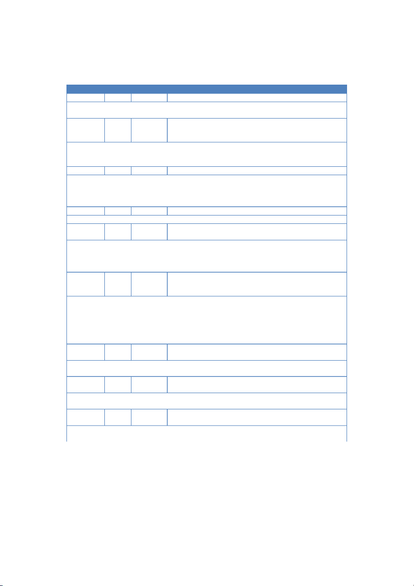
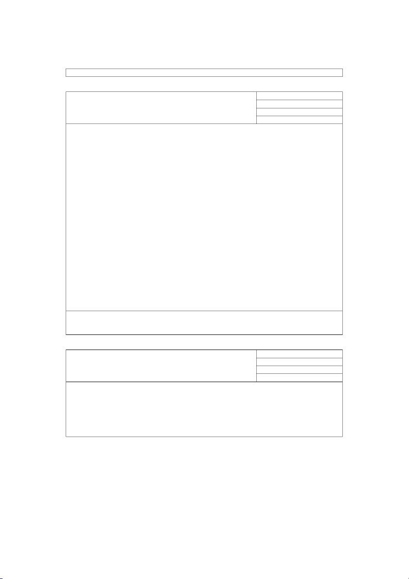
Ahn, Cho, Chotemateepirom, Haider, Zgraggen 10/10/2008 Sandcastle Team 26 February 2024 Revision History Date Version Author Description 11/12/2008 N/A Jaffer Outline created. 11/19/2008 N/A Jaffer
Added introductory sections and template for quality attribute scenarios. 11/20/2008 N/A Jaffer
Added quality attribute scenarios. Refined them based on team
inspection. Added difficulty ranking and added rankings for
quality attribute scenarios and constraints. 11/21/2008 N/A Jaffer
Added items to glossary. Added functional requirement
specifications and use cases. Changed quality attribute scenarios
after meeting with client. Added prioritization information. 11/21/2008 N/A Jaffer
Added the traceability matrix for requirement specifications. 11/22/2008 N/A Jaffer
Added version number and last changed date for requirements
specifications, use cases and quality attribute scenarios. A Change
Process was also added to the document, to make sure people
are aware of the procedure for editing this important document. 11/25/2008 N/A Jaffer
Incorporated changes from inspection. 12/2/2008 N/A Jaffer
Incorporated changes from another inspection. 12/3/2008 1.0 Jaffer
Adding clarifications to open issues after discussion with the client. 1/28/2009 1.1 Benjamas
Adding clarifications how to manage custom shape (FR3, UC07,
UC08, UC09, UC10) and added specific requirement for managing
project (FR12, UC26) after discussion with the client in the meeting on 1/28/2009. 4/9/2009 1.2 Benjamas
Added the details of default shapes and warning rules.
Updated requirements based on the UI discussion on 03/27/2008
Add two new quality attribute scenarios about modifiability. 6/22/2009 1.3 Guido
Architectural drivers cannot be assigned to views.
Add decomposition of a group and add the open issue that we are
not sure if it will be helpful.
Element and Relationships can’t have the same name.
No confirmation needed when removing elements or relationships. 7/12/2009 1.4 Guido
We decided to not delete the child view when deleting the parent element/relationship. 7/16/2009 1.5 Guido
I added an addendum. The first item is that we weakened the TC3. 7/28/2009 1.6 Guido
Update the ADS that it reflects all the changed we decided on during cycle 3. 7/28/2009 1.7 Sam
Removed the requirement to edit the text color for custom
element and relationship types. 7/29/2009 1.8 Sam
Removed the requirement to edit the text color for custom
element and relationship types. 7/30/2009 1.9 Guido
Update the ADS that it reflects all the changed we decided on during cycle 3.
Chotemateepirom, Cho, Ahn, Haider, Zgraggen Page 2 of 49 Sandcastle Team 26 February 2024 8/5/2009 1.10 Guido
Removed the QAS 6 which was replaced by QAS7 and QAS8 which are more specific 8/6/2009 1.11 Guido
Discussed all the highlighted things with Jaffer. 9/17/2009 1.12 Soo-Yung Added a use case (UC31)
Chotemateepirom, Cho, Ahn, Haider, Zgraggen Page 3 of 49 Sandcastle Team 26 February 2024
Document Approvals: The following signatures are required for approval of this document. Anthony J. Lattanze Date
Carnegie Mellon University/ISR faculty Guido Zgraggen Date Team Sandcastle Member Jaffer Haider Date Team Sandcastle Member Samuel Ahn Date Team Sandcastle Member Soo Yung Cho Date Team Sandcastle Member Benjamas Chotemateepirom Date Team Sandcastle Member
Chotemateepirom, Cho, Ahn, Haider, Zgraggen Page 4 of 49 Sandcastle Team 26 February 2024 Contents 1
Introduction......................................................................................................................................... 6 1.1
Purpose........................................................................................................................................ 6 1.2
Definitions, Acronyms and Abbreviations....................................................................................6 1.3
Change Process............................................................................................................................7 2
Project Overview.................................................................................................................................7 3
Architectural Drivers Overview............................................................................................................7 4
Functional Requirements.....................................................................................................................8 4.1
Template......................................................................................................................................8 4.2
Specifications...............................................................................................................................8 4.2.1
Allow designers to capture, categorize, and refine architectural drivers.............................8 4.2.2
Provide a drawing palette for rendering structures in views in the static, dynamic, and
physical perspective that provide a collection of predefined elements and relationship types that
are consistent with respect to perspective..........................................................................................9 4.2.3
Allow designers to define their own elements and relationship types..............................10 4.2.4
Provide a way to create element and relationship catalogs..............................................10 4.2.5
Allow designers to capture design rationale......................................................................11 4.2.6
Allow designers to explicitly assign architectural drivers to design decisions....................11 4.2.7
Provide a way for designers to define element “interfaces” statically, dynamically, and physically11 4.2.8
Allow designers to map elements to elements within a perspective.................................11 4.2.9
Allow designers to map elements to elements across perspectives..................................12 4.2.10
Provide the ability to use UML as a vocabulary for detailed design drawings...................12 4.2.11
Provide the ability to warn users when various design obligations have not been met....12 4.2.12
Allow designers to save, load, delete, and rename projects..............................................12 4.2.13
Allow designers to edit projects after they have been saved.............................................13 4.2.14
Facilitate collaborative design by allowing a community of designers to use the tool to
define and update the design............................................................................................................13 4.2.15
All interaction between designers and the tool will be through a graphical user interface 13 4.2.16
Print (or Presentation mode) formatting requirements.....................................................13
Chotemateepirom, Cho, Ahn, Haider, Zgraggen Page 5 of 49 Sandcastle Team 26 February 2024 4.3
Specifications Traceability Matrix..............................................................................................13 4.4
Use Case Modeling.................................................................................................................... 14 4.4.1
Domain Model...................................................................................................................14 4.4.2
Entities...............................................................................................................................14 4.4.3
Use Case List...................................................................................................................... 15 4.4.4
Use Cases...........................................................................................................................16 5
Quality Attribute Requirements........................................................................................................34 5.1
Template....................................................................................................................................34 5.2
Quality Attribute Scenarios........................................................................................................35 6
Constraints........................................................................................................................................ 38 6.1
Technical Constraints.................................................................................................................38 6.2
Business Constraints..................................................................................................................39 7
Prioritization......................................................................................................................................39 7.1
Priority scale.............................................................................................................................. 39 7.2
Difficulty ranking scale...............................................................................................................39 7.3
Use Cases...................................................................................................................................40 7.4
Quality Attribute Scenarios........................................................................................................41 7.5
Constraints................................................................................................................................. 41 7.5.1
Technical Constraints.........................................................................................................41 7.5.2
Business Constraints..........................................................................................................42 7.6
Significant Architectural Drivers................................................................................................42 8
Default shapes...................................................................................................................................42 8.1
Dynamic perspective..................................................................................................................42 8.1.1
Element types....................................................................................................................42 8.1.2
Relationship types..............................................................................................................44 8.2
Static perspective.......................................................................................................................44 8.2.1
Element types....................................................................................................................44 8.2.2
Relationship types..............................................................................................................45 8.3
Physical perspective...................................................................................................................45 8.3.1
Element types....................................................................................................................45 8.3.2
Relationship types..............................................................................................................45 9
Warning rules.................................................................................................................................... 46
Chotemateepirom, Cho, Ahn, Haider, Zgraggen Page 6 of 49 Sandcastle Team 26 February 2024 10
Addendum.....................................................................................................................................46 1 Introduction 1.1 Purpose
This document will be used to record, communicate and refine the architectural drivers for the project.
This document will act as the main repository of requirements for the length of the project.
The intended audience for this document is the Sandcastle team and the customer. These stakeholders
are to review the document and changes will be incorporated as per the change management process of the Sandcastle team. [SOW08]
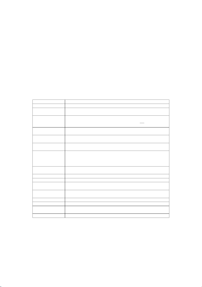
1.2 Definitions, Acronyms and Abbreviations ACDM
Architecture Centric Design Method JDK Java Development Kit Element Type
An element type is a shape in the palette, which is used to create an element in the canvas. Element
An element is used to represent a shape in the drawing canvas representing an
architectural item. A connector between two elements is not considered an element. Relationship Type
A relationship type is a connector in the palette, which is used to create a relationship in the canvas. Relationship
A relationship is an instance of a relationship type, and used to connect element(s) on the canvas. Assignment
This specifies the connection between an architectural driver and an element, relationship or mapping. Mapping
A mapping is created either between different views or between elements or
relationships and groups of elements and relationships. A mapping can be
hierarchical, or on the same level. Mappings between elements or
relationships and groups of elements and relationships can span across views. Toolbox
The collection of available elements and relationships types that can be used in a diagram canvas. Entity
The ACDM definition for an actor which could be a person or a system. Perspective
3 perspectives prescribed by ACDM; static, dynamic and physical. View
A view is a drawing in a perspective. There can be multiple views in a perspective. Shapes
An all encompassing term for elements and relationships (or element types
and relationship types, depending on the context). Task
A note created by the user to remind them of design activities. Group
A group is a set of elements and relationships. Element relationship
This catalog contains an overview of all the elements and relationships which catalogue
are present in a particular view. Design
This is the drawing the architect does in the tool. The term design is used in
Chotemateepirom, Cho, Ahn, Haider, Zgraggen Page 7 of 49 Sandcastle Team 26 February 2024
this document because architecture is used in many other ways which might confuse the reader. Canvas
Drawing area in the tool. This is the place where the architecture is drawn. Architecture
All of the diagrams including their elements and relationships as a
representation of a software system. The architecture also includes the
architectural drivers which are assigned to the elements and relationships. Architectural drivers
These consist of functional requirements, quality attributes, business
constraints and technical constraints. Can be assigned to elements, relationships and mappings. Architect The end user of the system. Child view
This is a view resulting from the decomposition of an element. In some cases,
depending on the context, this will be used to refer to all children,
grandchildren etc. views of an element. 1.3 Change Process
When making changes to the document, the date, name of person making the change and brief
description of the change must be added to the revision history table on the second page of this
document. New entries are added at the bottom of the table.
When making changes in a functional requirement specification, use case or a quality attribute
scenarios, the revision number of the item being changed must be increased by one and the last
changed date must be updated to the date when the change was made. Please only update the revision
number and last changed date when you are making a change in a requirement that actually changes
the meaning of the requirement. Do not update these attributes when fixing language errors. 2 Project Overview
The ACDM Architecture Tool is a tool that will allow the software architect to draw diagrams of design of
the software to be developed. Detailed project goals and all relevant contextual information for this
document is presented in the [SOW08] document.
3 Architectural Drivers Overview
The architectural drivers presented in this document include:
Functional Requirements: These requirements are presented in the form of specifications and
use cases. These are a refinement of the requirements documented in the raw requirements specification [RS08] document.
Quality Attribute Requirements: These requirements are presented in the form of quality
attribute scenarios. These scenarios are based on the quality attributes documented in the raw
requirements specification [RS08] document.
Business Constraints: These are the business constraints documented in the raw requirements specification [RS08] document.
Chotemateepirom, Cho, Ahn, Haider, Zgraggen Page 8 of 49 Sandcastle Team 26 February 2024
Technical Constraints: These are the technical constraints documented in the raw requirements specification [RS08] document.
These architectural drivers will influence the architectural design and implementation of the project.
Additionally, they will impact the schedule and quality of the project. As a whole these architectural
drivers define the scope of the project.
The elicitation process by which these architectural drivers were gathered is detailed in the [PDP08] document.
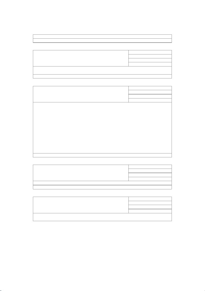
4 Functional Requirements 4.1 Template
Title of functional requirement ID: unique identifier. specification
Priority: priority integer based on the priority table.
Version: integer version number.
Last Changed: Date this specification was last changed. Both Version
and this field will be changed at the same time. Only changes that
affect the functionality should affect these two fields, and not minor grammatical changes.
Description of the requirement specification.
Open Issues: These are any ambiguities or conflicts in requirements that need to be clarified with the
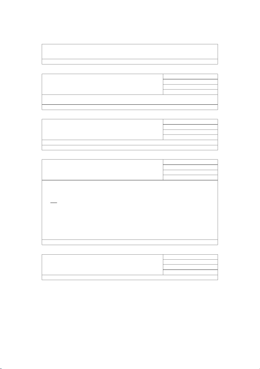
client. Additionally, these can be issues that the team needs to solve on their own. 4.2 Specifications
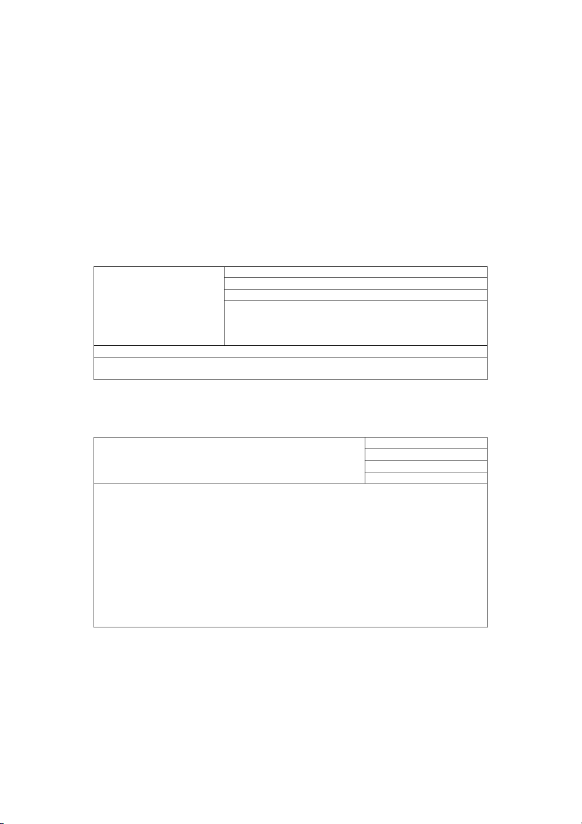
Prioritization scale has been defined in section 7.1. ID: FR1
4.2.1 Allow designers to capture, categorize, and refine Priority: 1 architectural drivers Version: 1
Last Changed: 11/22/2008
Architecture drivers should be categorized in the following categories: Functional Requirement Quality Attribute Scenarios Technical Constraint Business Constraint
Users cannot define their own categories.
Information to be captured for each architecture driver is listed in [lat08] (stage 2). Functional
requirements should use the use case and entity templates. Quality attribute scenarios should use the 6
step template ([lat08] page 222, chapter 9, Table9.16). Simple templates for business and technical
constraints are also present in [lat08].
The architect should be prompted to enter the architectural drivers before they create the design. This
Chotemateepirom, Cho, Ahn, Haider, Zgraggen Page 9 of 49 Sandcastle Team 26 February 2024
should be done in an unobtrusive way. Also, for each architecture driver, a certain list of actions should
be performed (writing prose description, rationale). If these actions are not performed, the user should
be notified, again in an unobtrusive way.
Refining architectural drivers will be facilitated in allowing annotations on elements. Architecture drivers
will be mapped onto elements or relationships, and thus there will be a collection of annotations
attached with a driver. (see requirements traceability table for related requirements)
The purpose of this feature is to have users use the tool as the primary storage for their architectural
drivers. Thus the interface and features for this requirement must allow them to perform the basic tasks
of adding and editing data and also take into account other features that they might need.
More detail about usage of architecture drivers in FR6. Open Issues ID: FR2
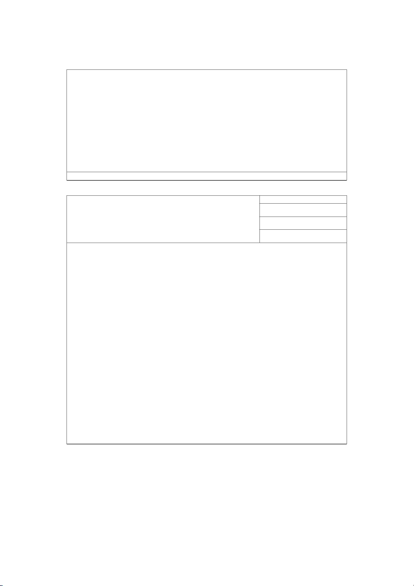
4.2.2 Provide a drawing palette for rendering structures Priority: 1
in views in the static, dynamic, and physical
perspective that provide a collection of predefined Version: 1
elements and relationship types that are consistent
Last Changed: 11/22/2008
with respect to perspective
List of element and relationship types to have in predefined list for each perspective (see section 8 for more information): Dynamic o Process o Threads o Objects o Data store o Data flow o Events o Interrupts o Call return Static o Modules o Procedure o Class o Uses o Inherits Physical o Anything in the physical world
The tool will provide the user the ability to create multiple views in a particular perspective that will act
as canvases for architectural diagrams.
In each view, an element or relationship must have a unique name. (see FR3 for more information)
Chotemateepirom, Cho, Ahn, Haider, Zgraggen Page 10 of 49 Sandcastle Team 26 February 2024 Open Issues ID: FR3
4.2.3 Allow designers to define their own elements and Priority: 1 relationship types Version: 1.1 Last Changed: 1/28/2009
Each perspective will have its own set of element and relationship types. Across perspectives, the name
of an element and relationship type must be unique. There will be no check on the actual way the element or relationship looks.
When creating a custom element or relationship type, the following information should be asked:
Ask whether it is an element or relationship Get a name Get a description
Restricted to which perspective. o
Search for the same name in all perspectives and warn the user. Don’t allow them to
create a duplicate. No duplicates across perspectives.
Drawing of the element type. In case of a relationship type, it would just be properties of how the line and arrowheads look.
Users should be able to take a predefined element or relationship type, modify it and save it as a custom
type. There should also be a quick way to revert back to default element and relationship types.
The user should be able to specify the color and attributes for different parts of the element and relationship types.
All shapes should be portable and should be packaged within a file if it uses custom shapes. When
custom shapes are created, the default behavior should be to have those custom shapes only visible at that project level. Open Issues
There should be an option to promote a custom shape to the application level, to make it available to other projects. ID: FR4
4.2.4 Provide a way to create element and relationship Priority: 1 catalogs Version: 2.1 Last Changed: 4/7/2009
The element and relationship catalogs will be at the view level. It will be a table containing all elements
and relationships in the view, with the following information provided for each:
Element: "Responsibilities", "Provides", and "Requires"
Relationship: "Responsibilities" Group: "Responsibilities".
The user should be able to enter these values (as plain text) directly into the relationship catalog.
Chotemateepirom, Cho, Ahn, Haider, Zgraggen Page 11 of 49 Sandcastle Team 26 February 2024 Open Issues ID: FR5
4.2.5 Allow designers to capture design rationale Priority: 1 Version: 1
Last Changed: 11/22/2008
Rationale is attached with each view of a perspective. Rationale will be in the form of prose. Open Issues ID: FR6
4.2.6 Allow designers to explicitly assign architectural Priority: 1
drivers to design decisions Version: 1
Last Changed: 11/22/2008
The user must be allowed to manually assign an architectural driver to particular elements and
relationships in the architecture.
The architecture drivers will be used in the tool in the following ways:
1. Assign to elements or relationships
2. Assign to a decomposition mapping (between an element and a view)
3. Assign to a mapping between elements or groups of elements (FR8 & FR9)
The assignment must propagate down to child elements and relationships when an element is
decomposed. Decomposing an element will result in a view. The decomposed element and the resulting
view will have a parent child relationship.
Architectural drivers cannot be assigned to views. Open Issues ID: FR7
4.2.7 Provide a way for designers to define element Priority: 3
“interfaces” statically, dynamically, and physically Version: 1
Last Changed: 11/22/2008
Interfaces are at the code level. This is a tentative requirement. Open Issues ID: FR8
4.2.8 Allow designers to map elements to elements Priority: 1 within a perspective Version: 1
Last Changed: 11/22/2008
The user must be allowed to group elements together, and create mappings between elements or
groups of elements in the same perspective.
Chotemateepirom, Cho, Ahn, Haider, Zgraggen Page 12 of 49 Sandcastle Team 26 February 2024
Additionally, the user should be allowed to create mappings between views.
The mappings type can be hierarchical or non-hierarchical.
They should be able to describe the mappings using prose. Open Issues: ID: FR9
4.2.9 Allow designers to map elements to elements Priority: 2 across perspectives Version: 1
Last Changed: 11/22/2008
The user must be allowed to perform the same operations as in FR8 for elements and groups of
elements and views in different perspectives. Open Issues ID: FR10
4.2.10 Provide the ability to use UML as a vocabulary for Priority: 3
detailed design drawings Version: 1
Last Changed: 11/22/2008 Not required at the moment. Open Issues ID: FR11
4.2.11 Provide the ability to warn users when various Priority: 2
design obligations have not been met Version: 2 Last Changed: 4/7/2009
The user must be warned in the following cases (See section 9 for details):
Not assigning architecture drivers to elements and relationships.
Not having a rationale for a view.
Not having element relationship catalogues. The user needs to enter the details for catalogues.
There’s a missing perspective.
The above warnings could be shown as ‘compiler warnings’ as an example.
The user can customize their own design obligations. They should be allowed to manage a todo list in
which they can add task titles and priorities. They should have the ability to mark a task as completed and be able to delete tasks. Open Issues ID: FR12
4.2.12 Allow designers to save, load, delete, and rename Priority: 1 projects Version: 1.1 Last Changed: 1/28/2009
Have only one project open in the application at a time.
Chotemateepirom, Cho, Ahn, Haider, Zgraggen Page 13 of 49
Tài liệu liên quan:
-
Tìm hiểu về Hyperledger Fabric College | Báo cáo đồ án Công nghệ thông tin
203 102 -
Đề cương nhập môn công nghệ thông tin | Đại học Văn Lang
234 117 -
Tham khảo ôn tập lý thuyết Công nghệ thông tin | Đại học Văn Lang
164 82 -
Xây dựng ứng dụng Quản lý phân bón diêm tro và thuốc trừ sâu | Báo cáo đồ án thực tập công nghệ thông tin
220 110 -
WEBSITE Thương Mại Điện Tử Bán Quần Áo | Báo cáo Công nghệ thông tin
220 110