Bài giảng The Unified Modelling Language (UML) - Part 2 môn Lập trình hướng đối tượng | Trường Đại học Khoa học, Đại học Huế
Bài giảng The Unified Modelling Language (UML) - Part 2 môn Lập trình hướng đối tượng | Trường Đại học Khoa học, Đại học Huế. Tài liệu được sưu tầm giúp bạn tham khảo, ôn tập và đạt kết quả cao. Mời bạn đọc đón xem.
Môn: Lập trình hướng đối tượng (LTHDT) 6 tài liệu
Trường: Trường Đại học Khoa học, Đại học Huế 52 tài liệu
Tác giả:


Preview text:
Applied Programming and Design Principles Lecture 6 The Unified Modelling Language (UML) - Part 2 Object Oriented Programming using C# Lesson’s objectives • UML Class Diagrams • Denoting Relationships • Types of Association An Introduction to UML
• This session will introduce you to the roles of the Unified Modelling
Language (UML) and explain the purpose of four of the most common
diagrams (class diagrams, object diagrams, sequence diagrams and package diagrams)
• These diagrams are used extensively when describing software
designed according to the object-oriented programming approach An Introduction to UML
• In UML 2, there are two basic categories of diagrams: structure diagrams and behavior diagrams
• Every UML diagram belongs to one these two diagram categories
• The purpose of structure diagrams is to show the static structure of the system
being modeled. They include the class, component, and or object diagrams
• Behavioral diagrams show the dynamic behavior between the objects in the
system, including things like their methods, collaborations, and activities An Introduction to UML
• It is, on the other hand, a precise diagramming notation that will
allow program designs to be represented and discussed
• The diagrams represent technical information they must be precise
and clear – in order for them to work - therefore there is a precise
notation that must be followed UML Class diagrams
• Classes are the basic components of any object oriented software
system and UML class diagrams provide an easy way to represent these
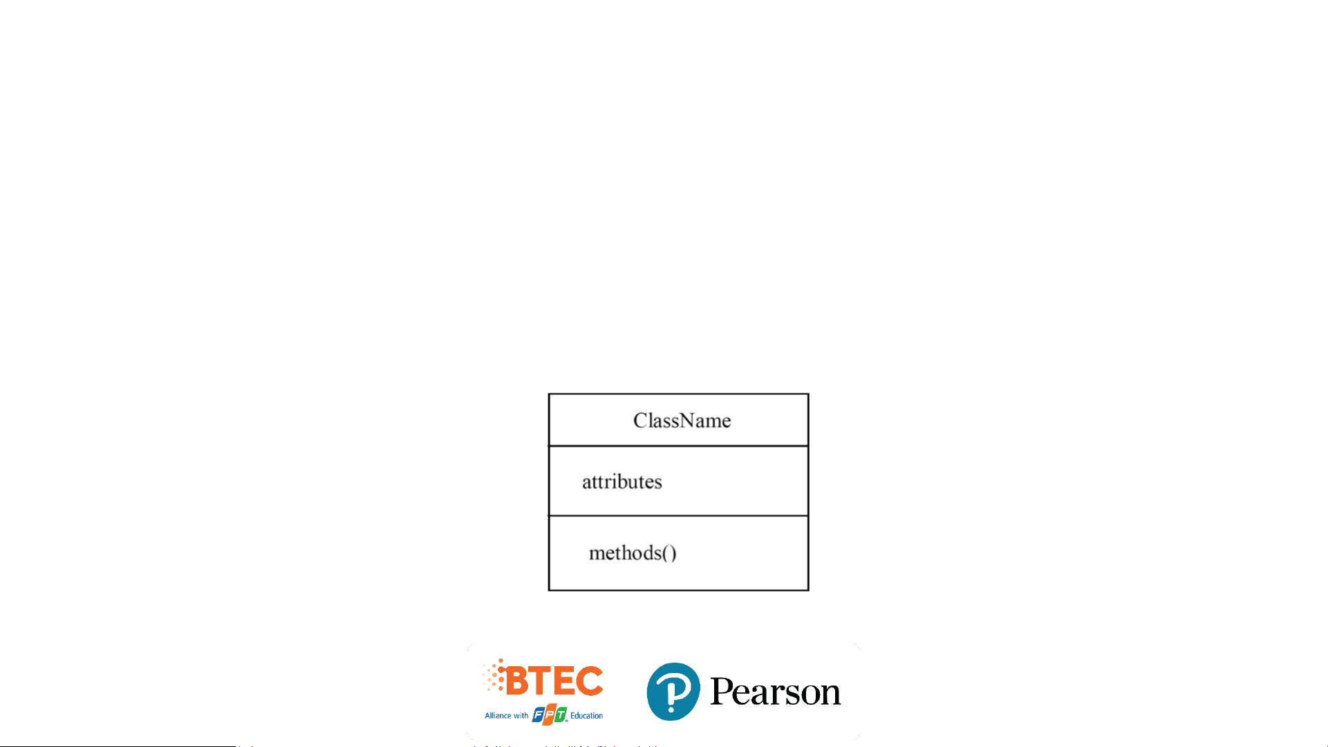
• Thus a class diagram shows the architecture of a system A class consists of
• A unique name (conventionally starting with an uppercase letter)
• A list of attributes (int, double, boolean, String etc) • A list of methods Class diagram
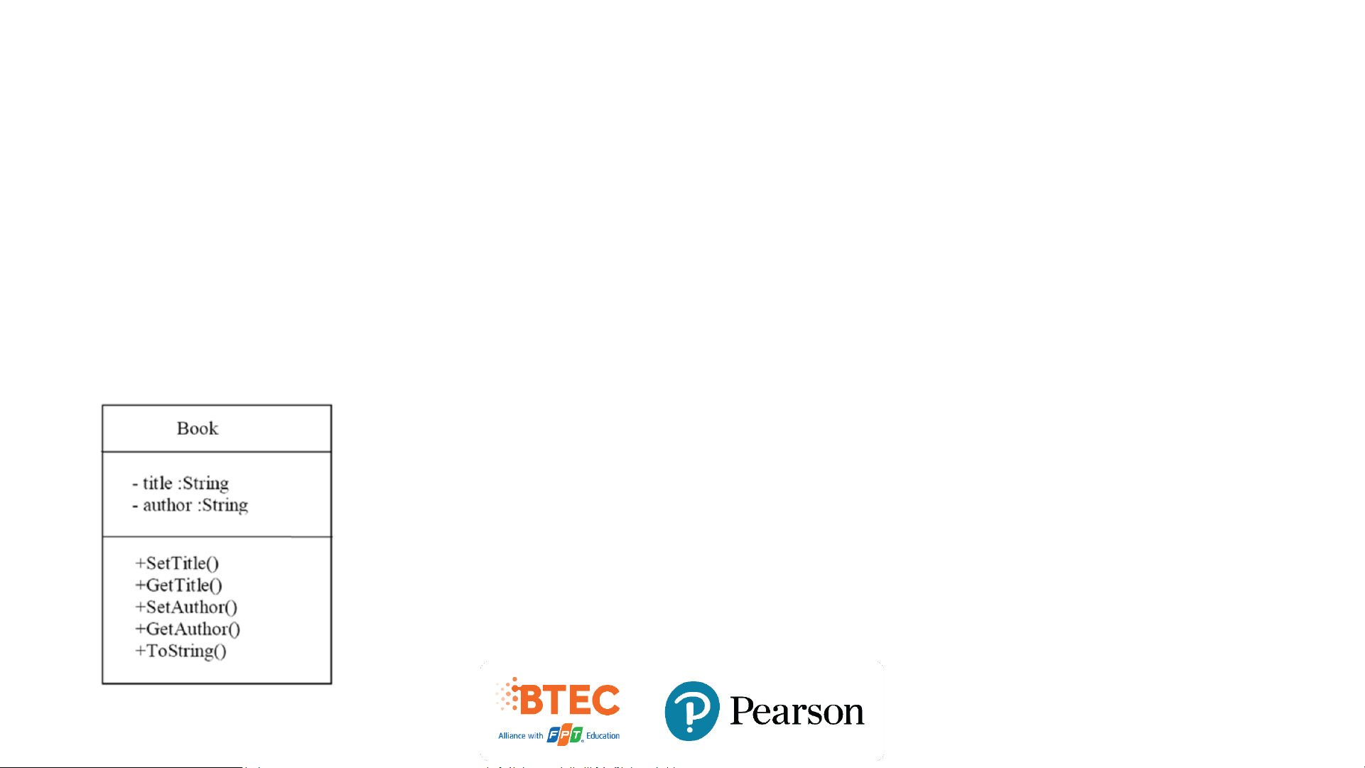
• For attributes and methods visibility modifiers are shown (+ for public
access, – for private access).
• Attributes are normally kept private and methods are normally made public. Exercise
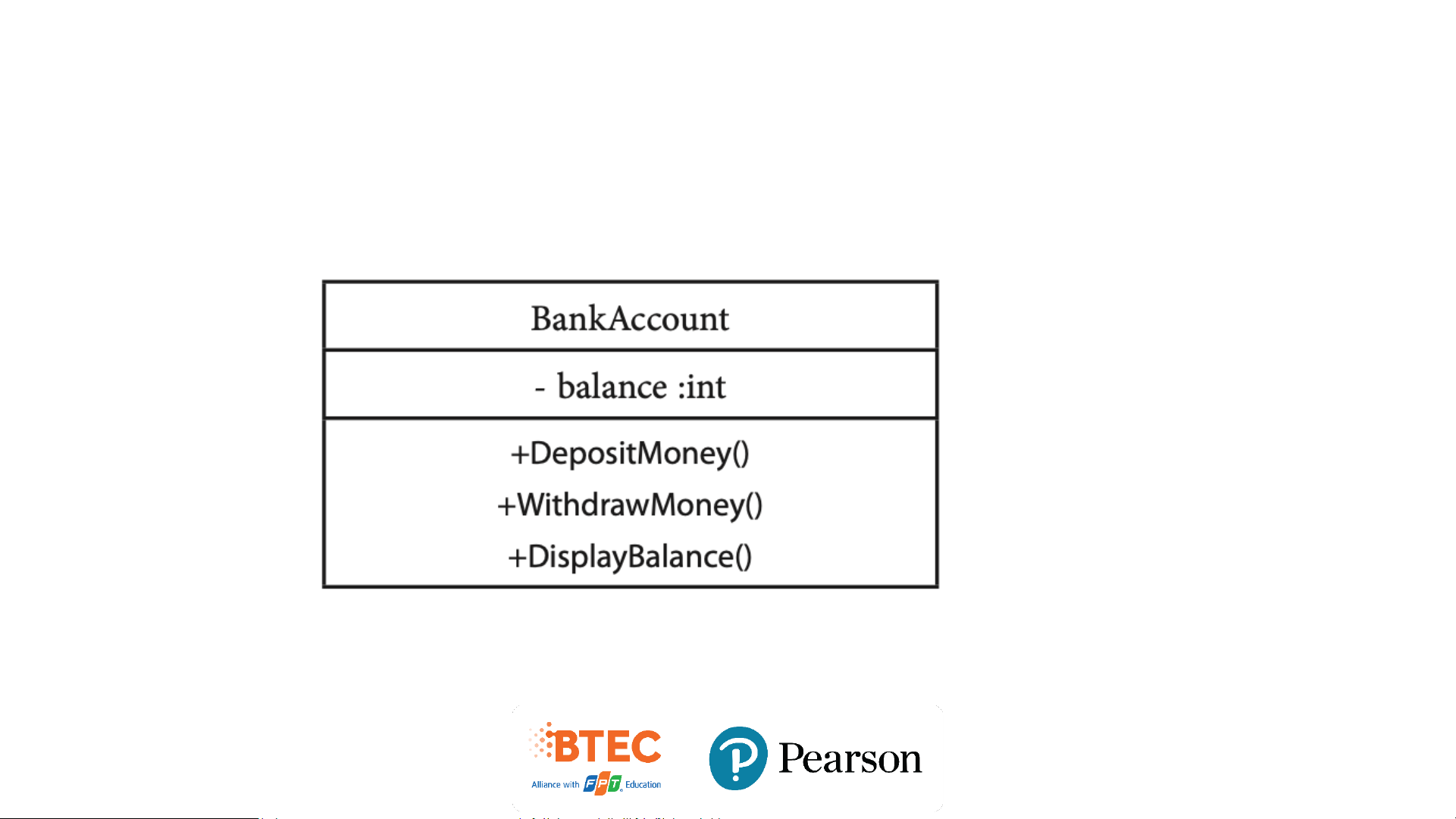
• Draw a diagram to represent a class called ‘BankAccount’ with the attribute balance (of type int) and
methods DepositMoney(), WithdrawMoney() and DisplayBalance(). Show appropriate visibility modifiers. Solution Solution
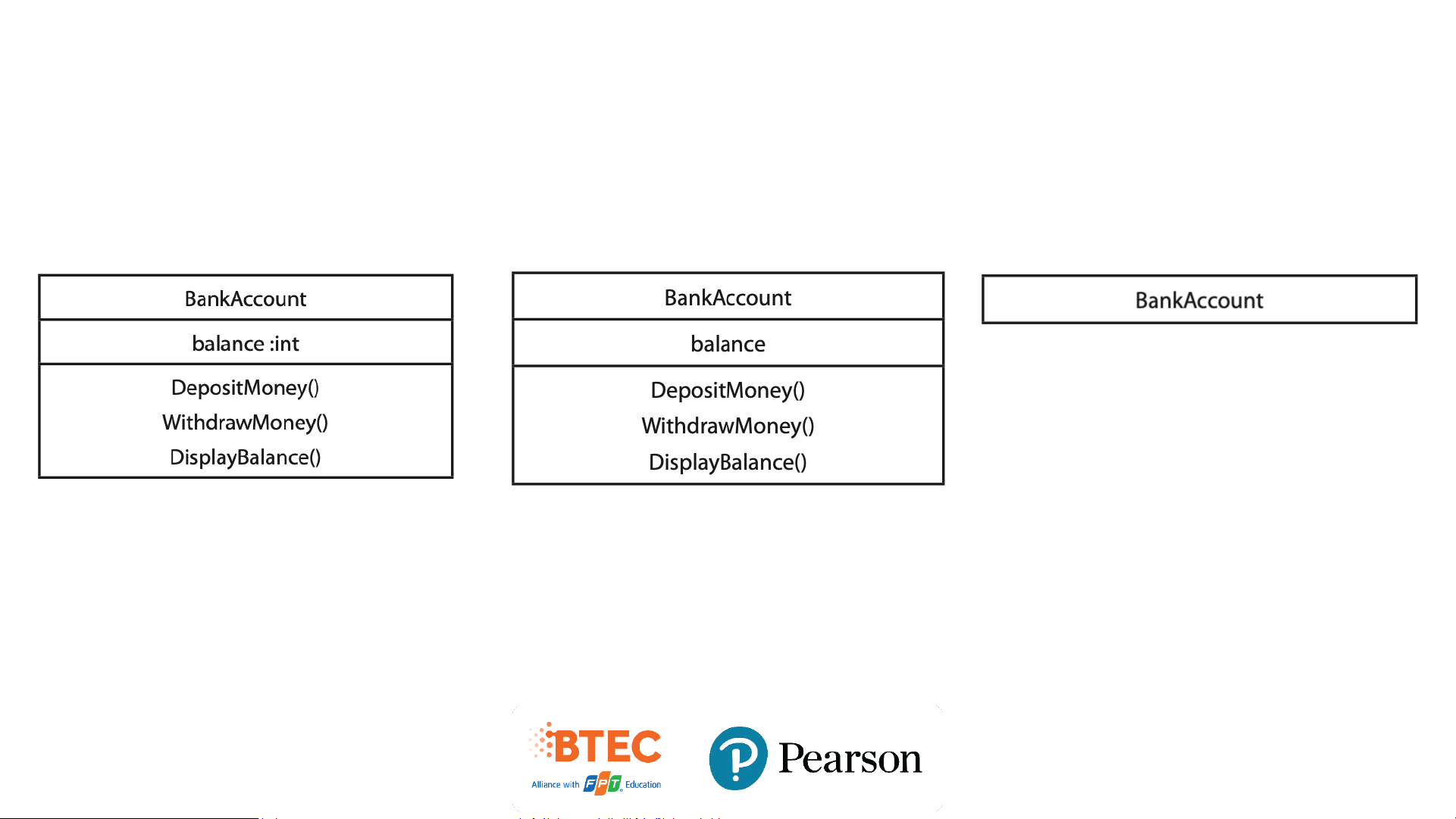
• UML allows us to suppress any information we do not wish to highlight in our diagrams
• This allows us to suppress irrelevant detail and bring to the readers
attention just the information we wish to focus on.
The following are all valid class diagrams The access modifiers not Access modifiers and the data
The attributes and methods not shown types not shown shown Relationships
• Some classes wil make use of other classes.
• These relationships are shown by arrows
• Different type of arrow indicate different relationships (including
inheritance and aggregation relationships).
Generalization / specialization • Inheritance • Interfaces Relationships • Navigability • Multiplicity • Dependency • Aggregation • Composition Exercise
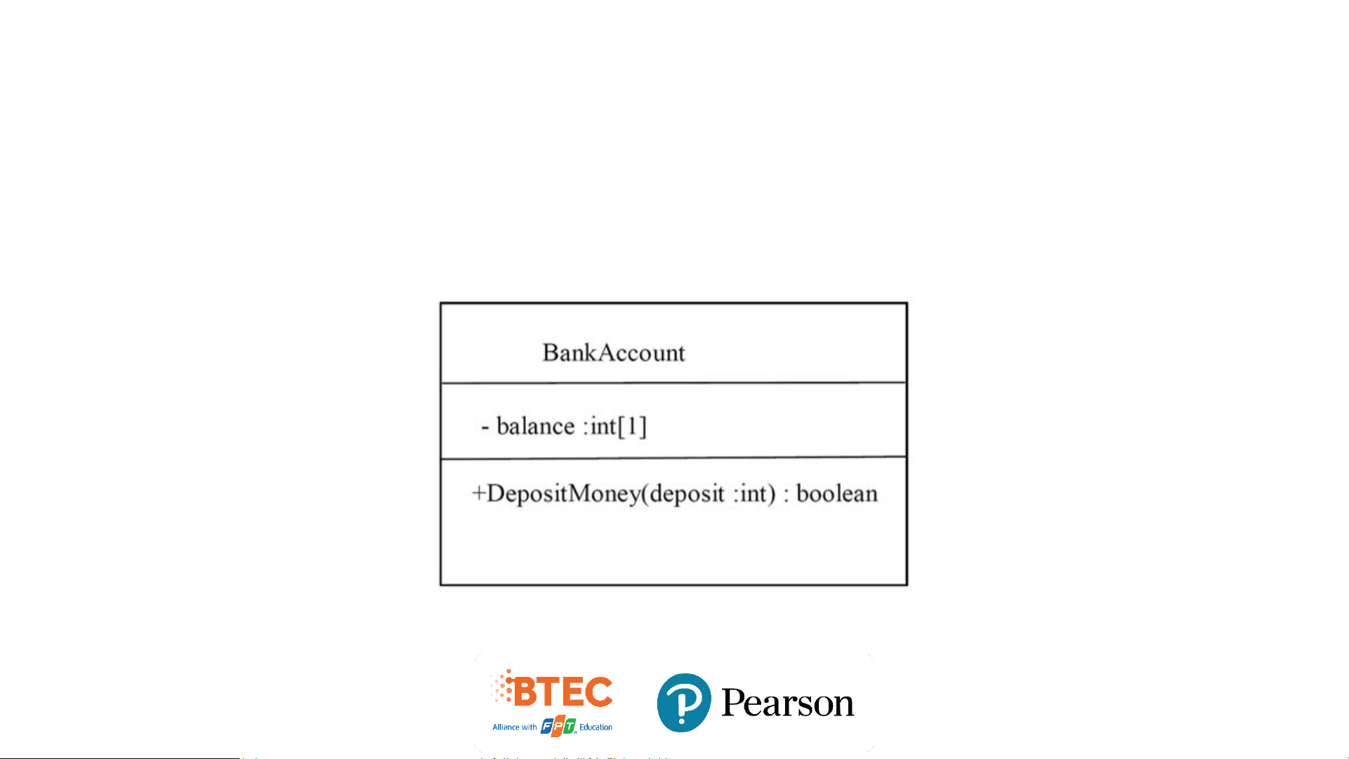
• Draw a diagram to represent a class called ‘BankAccount’ with a
private attribute balance (this being a single integer) and a public
method DepositMoney() which takes an integer parameter, ‘deposit’
and returns a boolean value. Fully specify all of this information on a UML class diagram. Solution Denoting Relationships
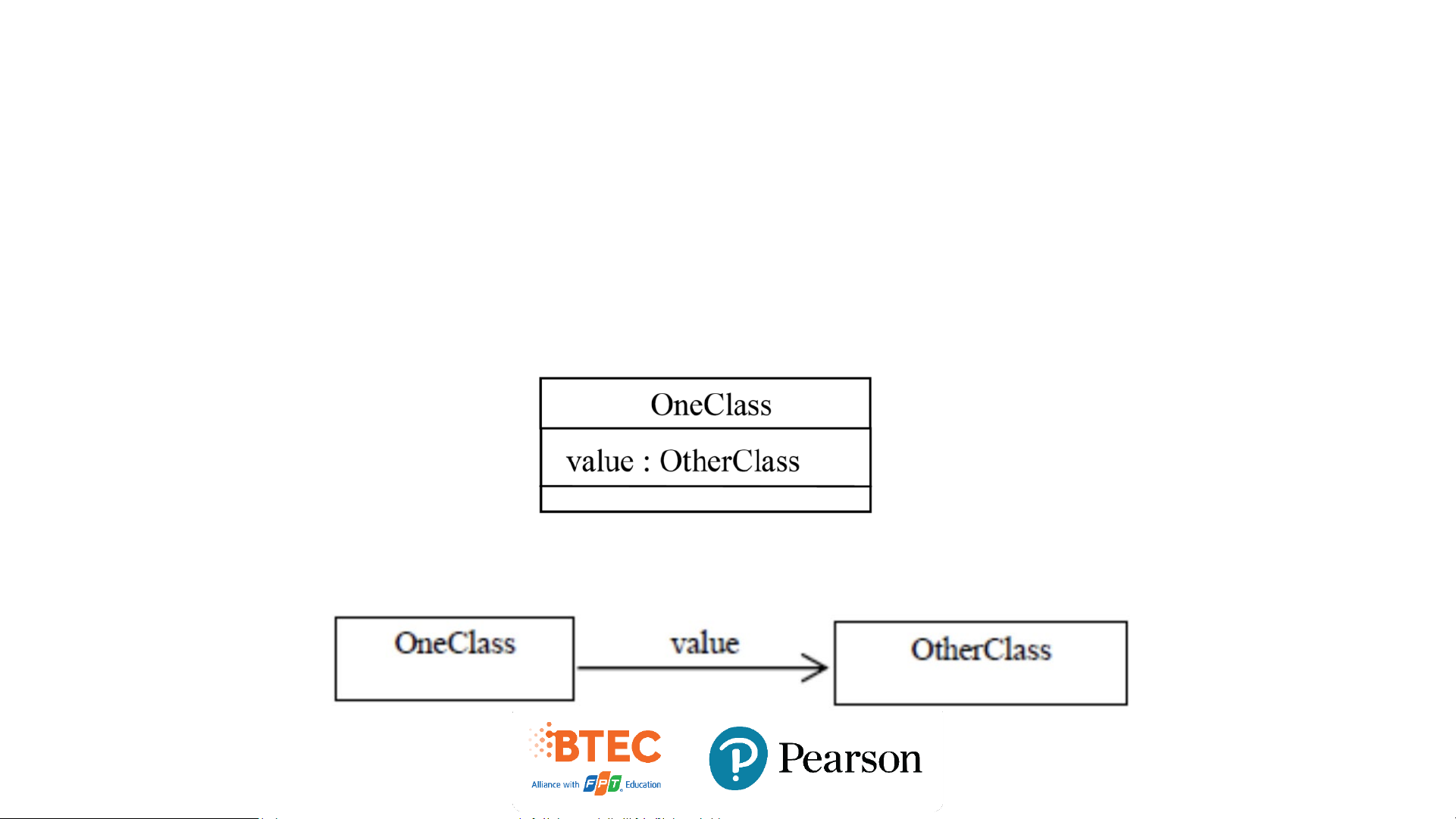
• The figure above shows a class ‘OneClass’ that has an attribute ‘value’.
• We use an association when we want to give two related classes, and their
relationship, prominence on a class diagram
• We could denote exactly the same information by the diagram below.
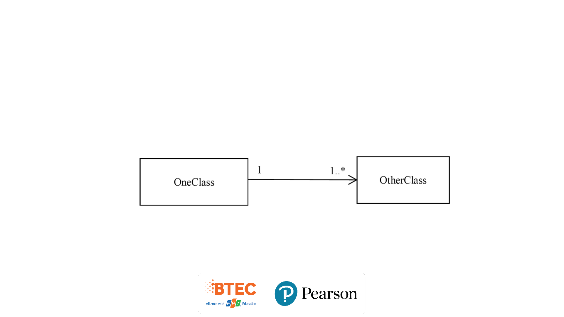
Multiplicity at both ends of an association
• This implies that ‘OneClass’ maintains a collection of objects of type ‘OtherClass’. Exercise
Tài liệu liên quan:
-
Bài tập môn Lập trình hướng đối tượng | Trường Đại học Khoa học, Đại học Huế
29 15 -

Bài giảng Overview of Programming Paradigms môn Lập trình hướng đối tượng | Trường Đại học Khoa học, Đại học Huế
26 13 -
Tóm tắt kiến thức Môn Lập trình hướng đối tượng | Trường Đại học Khoa học, Đại học Huế
89 45 -
Lộ Trình Lập Trình JAVA | Môn Lập trình hướng đối tượng - Trường Đại học Khoa học, Đại học Huế
75 38