Bài tập thường kỳ số 1 môn Kết cấu hàng không | Học viện Hàng Không Việt Nam
The lever is attached to the shaft A using a key that has a width and length of 25 mm. If the shaft is fixed and a vertical force of 200 N is applied perpendicular to the handle as shown in Figure 1 ... Tài liệu được sưu tầm gồm 7 trang, giúp các bạn ôn luyện và phục vụ cho việc học tập, đạt kết quả tốt. Mời các bạn đón xem!
Môn: Kết cấu hàng không 1 8 tài liệu
Trường: Học viện Hàng Không Việt Nam 639 tài liệu
Tác giả:
Preview text:
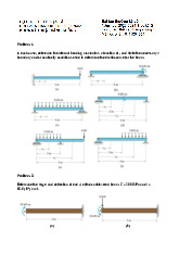
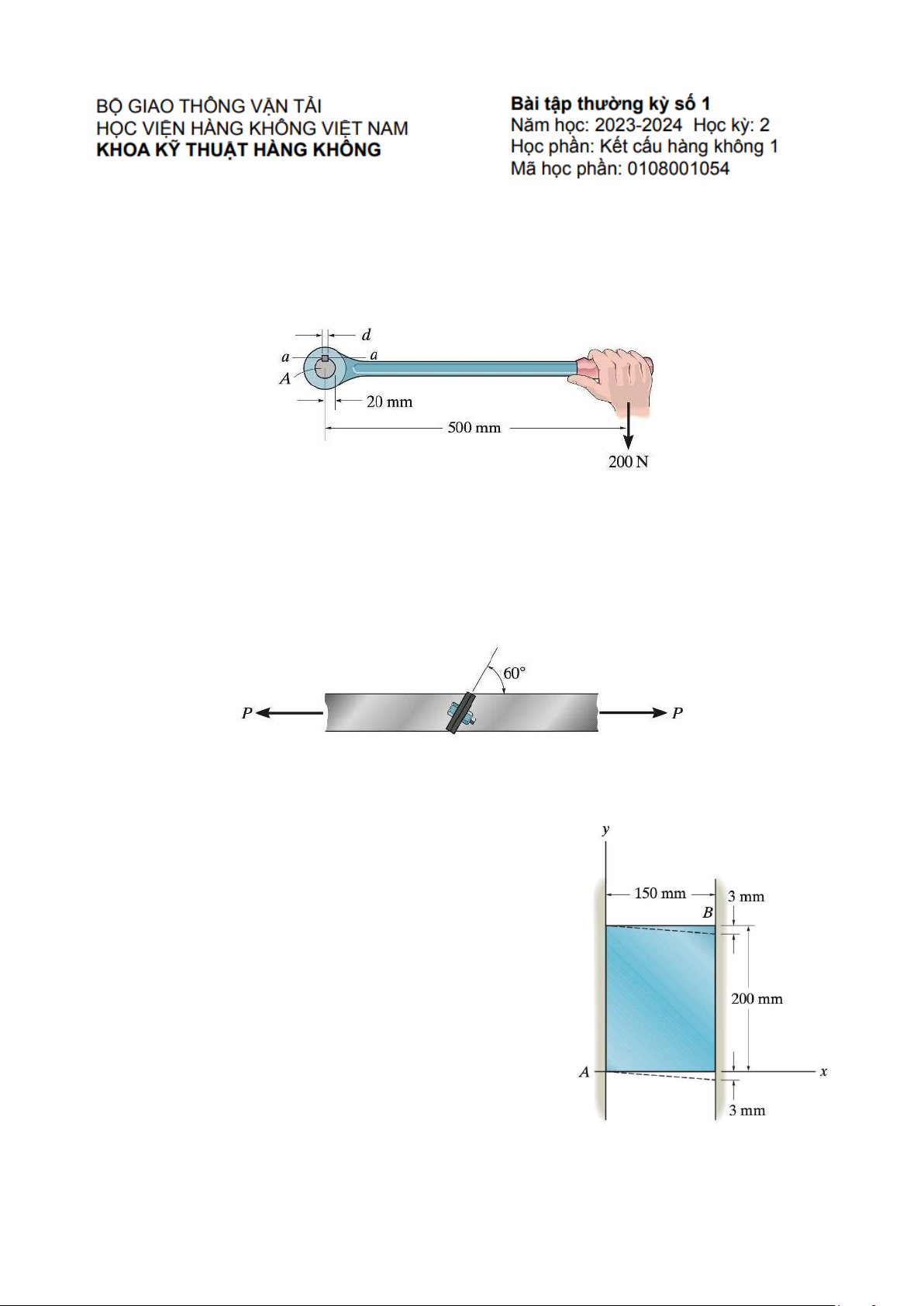
Problem 1.
The lever is attached to the shaft A using a key that has a width and length of 25 mm. If the shaft d
is fixed and a vertical force of 200 N is applied perpendicular to the handle as shown in Figure 1,
determine the dimension d if the allowable shear stress for the key is τallow= 35 MPa. Figure 1 Problem 2.
The tension member is fastened together using two bolts, one on each side of the member as
shown in Figure 2. Each bolt has a diameter of 0.3 in. Determine the maximum load that can be P
applied to the member if the allowable shear stress for the bolts is τallow = 12 ksi and the allowable
average normal stress is σallow = 20 ksi. Figure 2 Problem 3.
An air-fil ed rubber bal has a diameter of 6 in. If the air
pressure within the bal is increased until the diameter
becomes 7 in., determine the average normal strain in the rubber. Problem 4.
The rectangular plate is subjected to the deformation shown
by the dashed line in Figure 3. Determine the average shear
strain γxy in the plate. Figure 3 Problem 5.
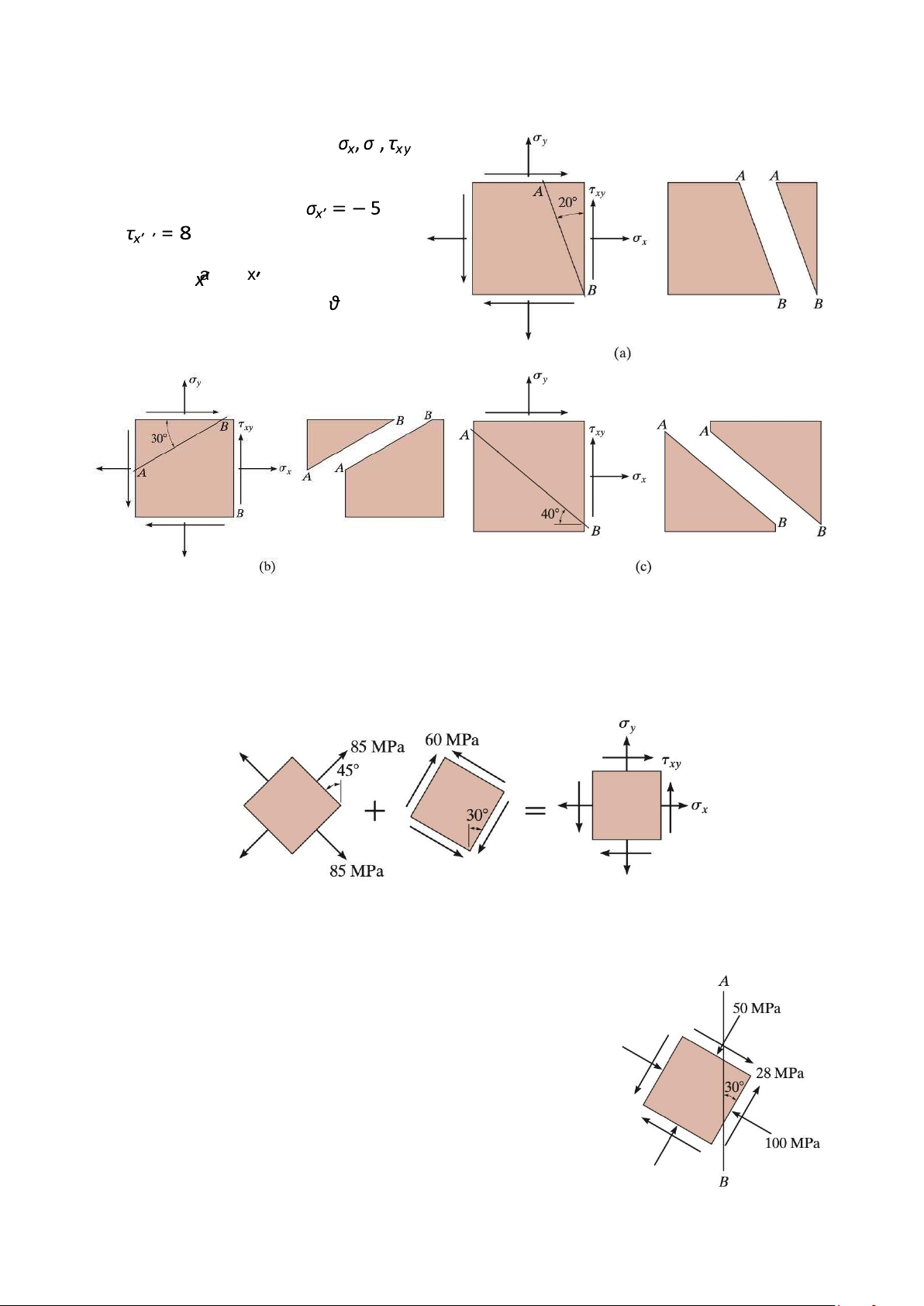
In each case, the state of stress y
produces normal and shear stress
components along section AB of the element that have values of kPa and kPa when calculated using y
the stress transformation equations.
Establish the and axes for each y
segment and specify the angle , then
show these results acting on each segment. Figure 4 Problem 6.
A point on a thin plate is subjected to the two stress components as shown in Figure 5. Determine
the resultant state of stress represented on the element oriented as shown on the right. Figure 5 Problem 7.
The state of stress at a point in a member is shown on the element
in Figure 5. Determine the stress components acting on the plane AB.
a. Solve the problem using the method of equilibrium.
b. Solve the problem using the stress transformation equation. Figure 6 Problem 8.
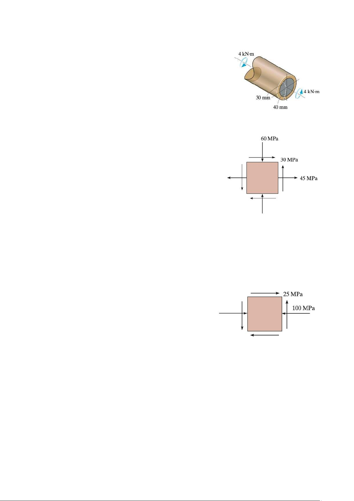
The hollow circular shaft in Figure 7 is subjected to the torque of 4
kN.m.Determine the principal stresses at a point on the surface of the shaft. Figure 7 Problem 9.
The state of stress at a point is shown on the element in Figure 8. Determine
(a) the principal stresses and
(b) the maximum in-plane shear stress and average normal
stress at the point. Specify the orientation of the element in each case. Figure 8 Problem 10.
Determine the equivalent state of stress on an element at the same point which represents (a) the principal stress, and
(b) the maximum in-plane shear stress and the associated average normal stress.
Also, for each case, determine the corresponding orientation
of the element with respect to the element shown and sketch the results on the element. Figure 9 Problem 11.
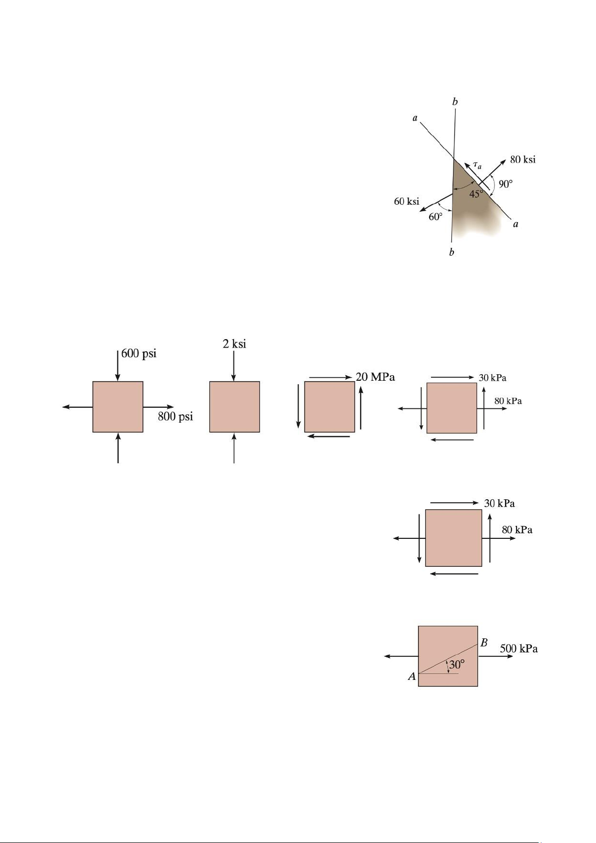
The stress acting on two planes at a point is indicated in Figure 10.
Determine the shear stress on plane a − a and the principal stresses at the point. Figure 10 Problem 12.
Draw Mohr s circle that describes each of the following states of stress. Figure 11 Problem 13.
Use Mohr s circle to determine the principal stresses at the point.
Also, find the corresponding orientation of the element with respect
to the element shown in Figure 12. Figure 12 Problem 14.
Use Mohr s circle to determine the normal stress and shear
stress acting on the inclined plane AB. Figure 13 Problem 15.
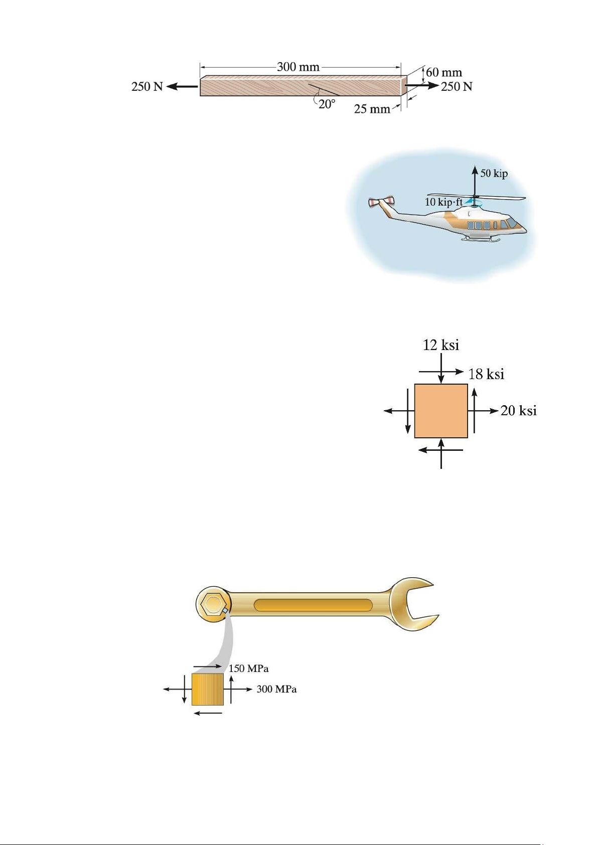
The grains of wood in the board in Figure 14 make an angle of 20¡ with the horizontal as
shown. Determine the normal and shear stresses that act perpendicular and parallel to the
grains if the board is subjected to an axial load of 250 N. Figure 14 Problem 16.
The rotor shaft of the helicopter is subjected to the
tensile force and torque as shown in Figure 15 when the
rotor blades provide the lifting force to suspend the
helicopter at midair. If the shaft has a diameter of 6 in.,
determine the principal stresses and maximum in-plane
shear stress at a point located on the surface of the shaft. Figure 15 Problem 17.
The state of plane stress at a critical point in a steel machine
bracket is shown in Figure 16. If the yield stress for steel is σY =
36 ksi, determine if yielding occurs using a. the maximum shear stress theory
b. the maximum distortion energy theory. Figure 16 Problem 18.
The state of stress acting at a critical point on a wrench is shown in Figure 17. Determine the
smallest yield stress for steel that might be selected for the part a. based on the maximum shear stress theory.
b. based on the maximum distortion energy theory. Figure 17 Problem 19.
The yield stress for a zirconium-magnesium alloy is σY = 15.3 ksi. If a machine part is made of this
material and a critical point in the material is subjected to in-plane principal stresses σ1 and σ2 = − 0.5σ1.
a. Determine the magnitude of σ1 that wil cause yielding according to the maximum shear stress theory.
b. Determine the magnitude of σ1 that wil cause yielding according to the maximum distortion energy theory. Problem 20.
Derive an expression for an equivalent torque Te that, if applied alone to a solid bar with a circular
cross section, would cause the same energy of distortion as the combination of an applied bending
moment M and torque . T Problem 21.
If a shaft is made of a material for which σY = 75 ksi, determine the maximum torsional shear stress required to cause yielding
a. using the maximum distortion energy theory.
b. using the maximum shear stress theory. Problem 22.
Derive an expression for an equivalent bending moment Me that, if applied alone to a solid bar with
a circular cross section, would cause the same energy of distortion as the combination of an
applied bending moment M and torque . T Problem 23.
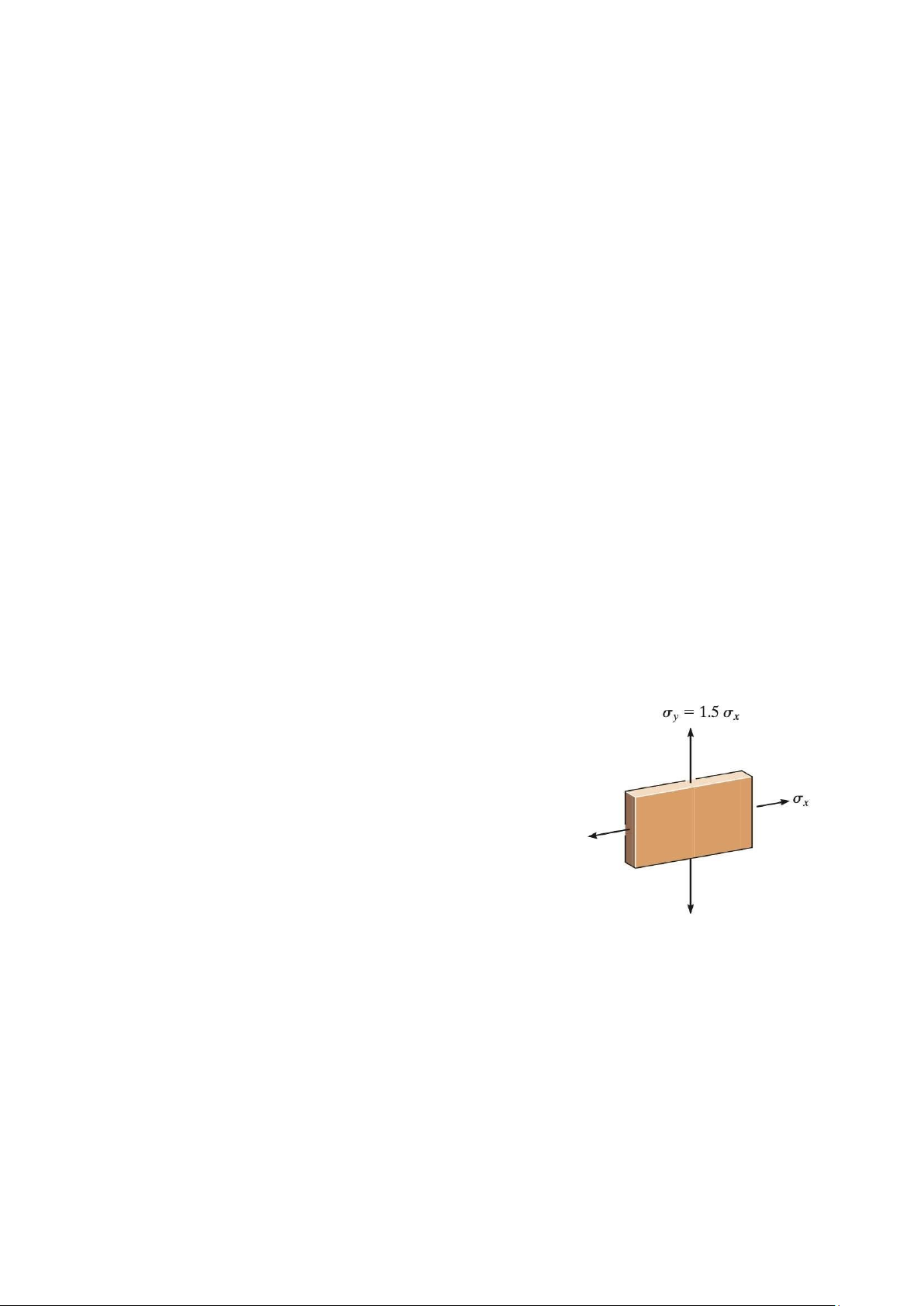
The plate is made of Tobin bronze, which yields at σY = 25 ksi.
If a tensile stress σy = 1.5σx is also applied.
a. Using the maximum shear stress theory, determine the
maximum tensile stress σx that can be applied to the plate.
b. Using the maximum distortion energy theory, determine the
maximum tensile stress σx that can be applied to the plate. Figure 18 Problem 24.
An aluminum alloy is to be used for a solid drive shaft such that it transmits 30 hp at 1200 rev/min.
Using a factor of safety of 2.5 with respect to yielding, determine the smallest-diameter shaft that
can be selected based on the maximum shear stress theory. σY = 10 ksi. Problem 25.
If a machine part is made of titanium (Ti-6A1-4V) and a critical point in the material is subjected to
plane stress, such that the principal stresses are σ1 and σ2 = 0.5σ1, determine the magnitude of σ1
in MPa that wil cause yielding according to
(a) the maximum shear stress theory, and (b)
the maximum distortion energy theory. Problem 26.
The 2-in.-diameter shaft in Figure 19 is made from brittle material having an ultimate stress of σult
= 50 ksi, for both tension and compression, determine if the shaft fails according to the maximum
normal stress theory. Use a factor of safety of 1.5 against rupture. Problem 27.
If the 2-in.-diameter shaft in Figure 19 is made from cast iron having tensile and compressive
ultimate stress of (σult)t = 50 ksi and (σult)c = 75 ksi respectively, determine if the shaft fails
according to the Mohr s failure criterion. Figure 19 Problem 23.
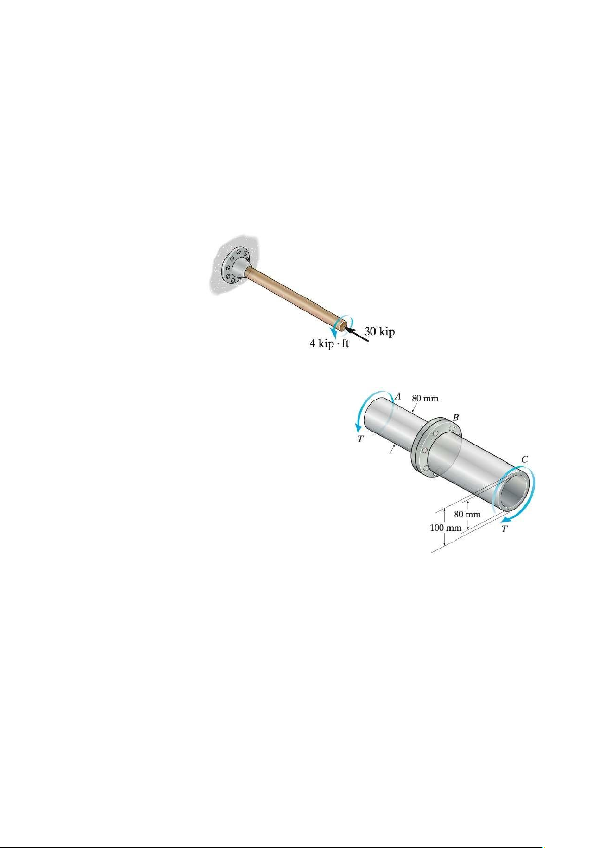
The shaft in Figure 20 consists of a solid segment AB and
a hollow segment BC, which are rigidly joined by the
coupling at B. If the shaft is made from A-36 steel,
a. determine the maximum torque T that can be applied
according to the maximum shear stress theory. Use a
factor of safety of 1.5 against yielding.
b. determine the maximum torque T that can be applied
according the maximum distortion energy theory. Use
a factor of safety of 1.5 against yielding. Figure 20