Bài tập Turbofan - English | Học viện Hàng Không Việt Nam
Bài tập Turbofan - English | Học viện Hàng Không Việt Nam được sưu tầm và soạn thảo dưới dạng file PDF để gửi tới các bạn sinh viên cùng tham khảo, ôn tập đầy đủ kiến thức, chuẩn bị cho các buổi học thật tốt. Mời bạn đọc đón xem!
Môn: English 101 (E.L1010) 66 tài liệu
Trường: Học viện Hàng Không Việt Nam 639 tài liệu
Tác giả:
Preview text:
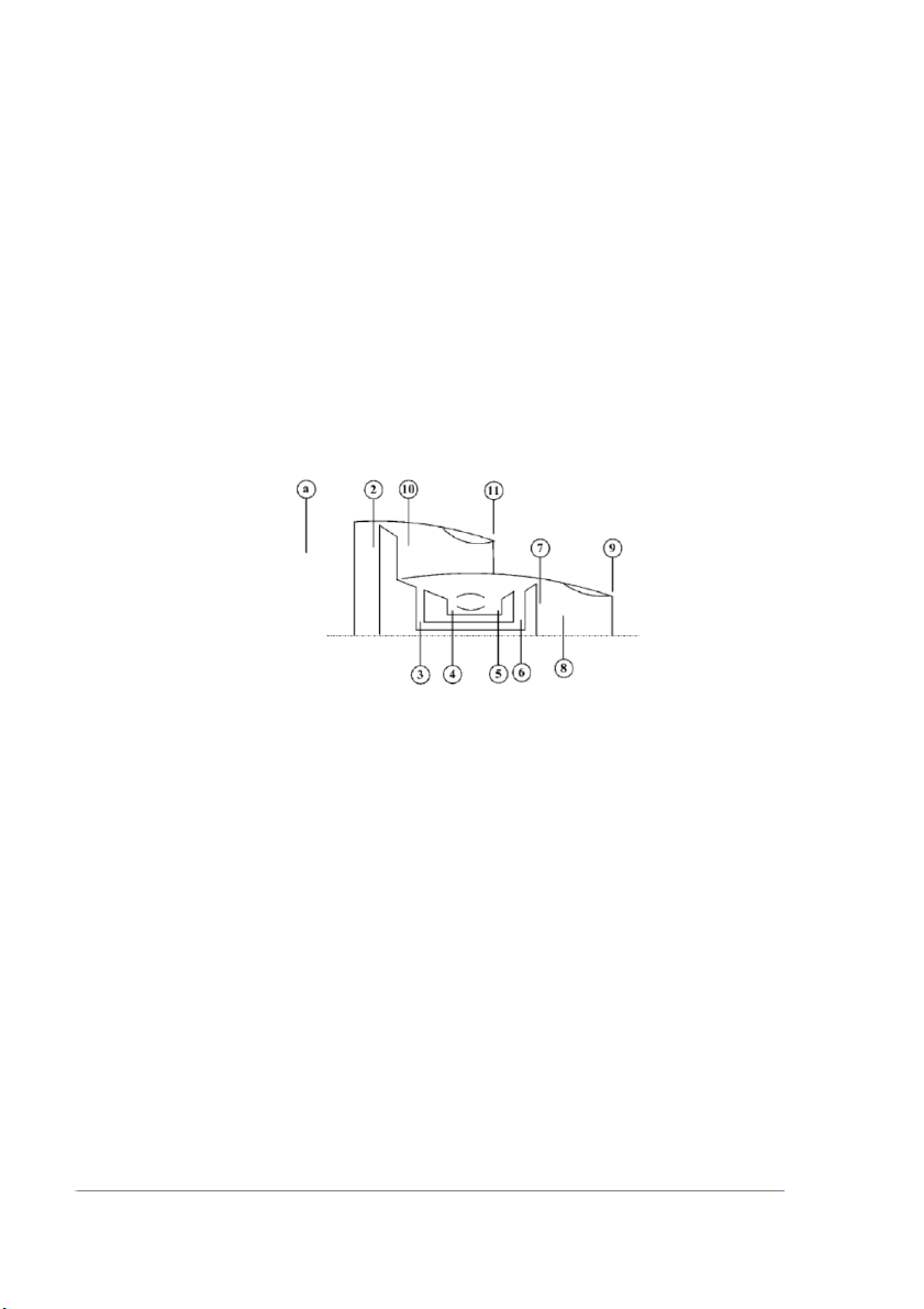
Problem 1. A high-bypass ratio (separate-exhaust) turbofan engine powers a
commercial transport. At the cruise condition, the flight and engine operating conditions are:
- M0 = 0,88; p0 = 15 kPa; T0 = −40◦C; 𝛾c = 1,4; cpc = 1004 J∕kg.K; 𝜋d = 0,995; 𝜋f = 1,6. ef = 0,90; 𝛼 = 8,0.
- Fan nozzle is convergent with 𝜋fn = 0,95; 𝜋c = 40; ec = 0,90; 𝜏𝜆 = 8,0; cpt = 1152
J∕kg.K. 𝛾t = 1,33, QR = 42000 kJ∕kg, 𝜋b = 0,95, 𝜂b = 0,992, 𝜂m = 0,95, et = 0.85.
- Primary nozzle is of convergent design and operates at 𝜋n = 0,98 Calculate
1. Plot T-s diagram for the cycle
2. Total pressures and temperatures throughout the engine and the fuel-to-air ratio
3. Nozzle exit static pressure p11 and p9
4. Ratio of fan-to-core thrust
5. Nondimensional specific thrust and TSFC in mg/s/N
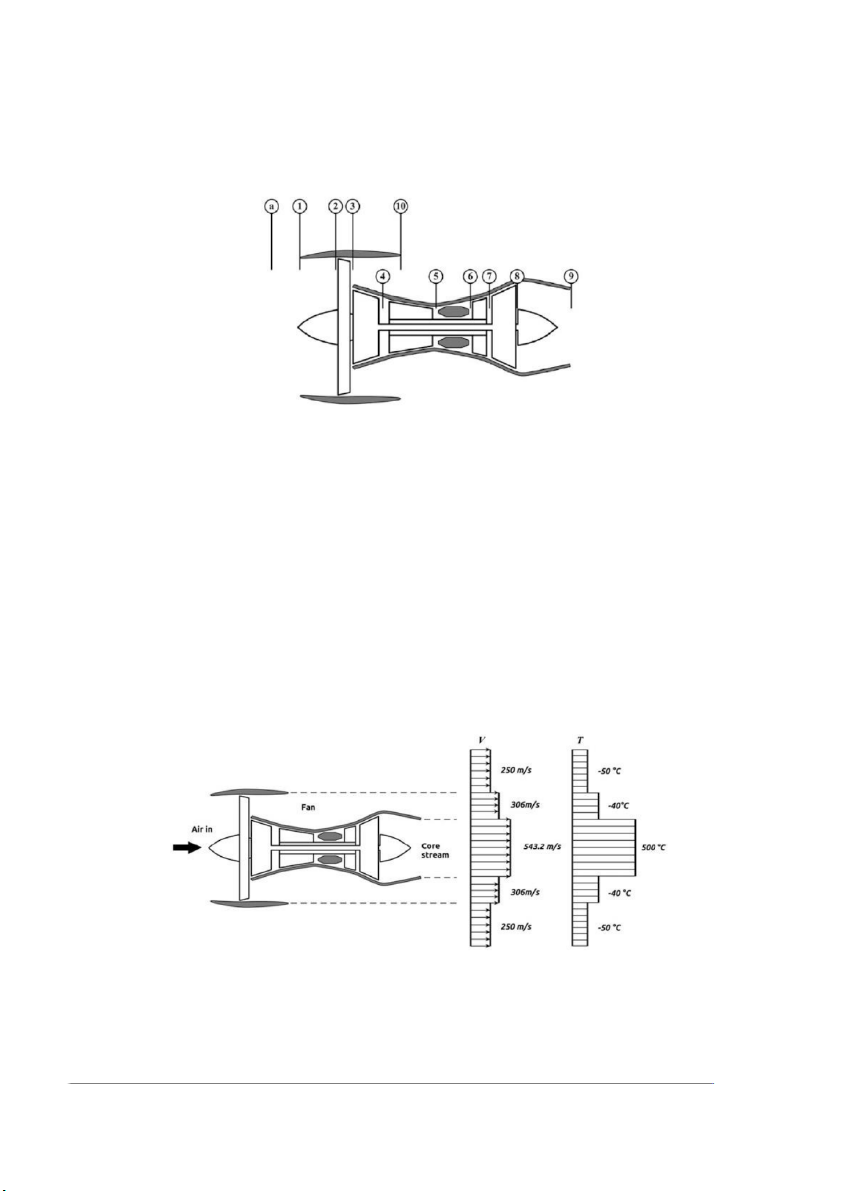
Problem 2 A double-spool turbofan engine; below figure blow, is used to power an
aircraft flying at speed of 250 m/s at an altitude of 11,000 m. As shown in the figure
below, the low-pressure turbine drives the fan and low-pressure compressor, while the
high-pressure turbine drives the high-pressure compressor. The engine has the fol owing data: - Bypass ratio=8.
- Total ingested air flow rate=180 kg/s.
- Overal pressure ratio OPR=35. - Fan pressure ratio=1.6.
- Pressure ratio of high-pressure compressor is four times that of the low-pressure compressor; πHPC=4 πLPC.
- Turbine inlet temperature=1650 K.
- Fuel heating value=43 MJ/kg.
Assuming all processes are ideal and neglecting any pressure drop, it’s required to: 1. Plot - T s diagram for the cycle 2. Find the thrust, 3. TSFC, 4. Efficiencies of the engine
5. Plot the velocity and temperature distribution over the engine cross section (rear end)
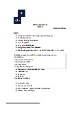
Problem 3 A double-spool turbofan engine is used to power an aircraft flying at speed
of 250 m/s at an altitude of 11,000 m. As shown in Figure, the low-pressure turbine
drives the fan and low-pressure compressor, while the high-pressure turbine drives the
high-pressure compressor. Inlet and outlet temperature and velocity of engine are
plotted beside the engine layout. The engine has the fol owing data: - Bypass ratio=8.
- Total ingested air flow rate=180 kg/s.
- Overal pressure ratio OPR=35.
- Pressure ratio of high-pressure compressor is four times that of the low-pressure compressor; πHPC=4 πLPC.
- Fuel heating value=43 MJ/kg.
Assuming all processes are ideal and neglecting any pressure drop, it’s required to find: 1. Plot - T s diagram for the cycle
2. Whether the nozzles are choked or not? 3. Fan pressure ratio 4. TIT 5. The thrust force
Tài liệu liên quan:
-

Top 1000 câu bài tập word form - English | Học viện Hàng Không Việt Nam
470 235 -
Extra Practice - English | Học viện Hàng Không Việt Nam
323 162 -
Bài tập chia động từ - English | Học viện Hàng Không Việt Nam
351 176 -
Human Resource Management - English | Học viện Hàng Không Việt Nam
311 156 -
Final project - English | Học viện Hàng Không Việt Nam
331 166