Chapter 14: Airport Operations - Tài liệu thực hành môn Quản trị bán hàng | Trường Cao đẳng Văn Lang Sài Gòn
Chapter 14: Airport Operations - Tài liệu thực hành môn Quản trị bán hàng | Trường Cao đẳng Văn Lang Sài Gòn. Tài liệu được sưu tầm giúp bạn tham khảo, ôn tập và đạt kết quả cao. Mời bạn đọc đón xem.
Môn: Quản trị bán hàng (vl) 2 tài liệu
Trường: Trường Cao đẳng Văn Lang Sài Gòn 30 tài liệu
Tác giả:


Preview text:
Chapter 14 Airport Operations Introduction
Each time a pilot operates an aircraft, the flight normally
begins and ends at an airport. An airport may be a small sod
field or a large complex utilized by air carriers. This chapter
examines airport operations, identifies features of an airport
complex, and provides information on operating on or in the vicinity of an airport. Airport Categories
The definition for airports refers to any area of land or water
used or intended for landing or takeoff of aircraft. This
includes, within the five categories of airports listed below,
special types of facilities including seaplane bases, heliports,
and facilities to accommodate tilt rotor aircraft. An airport
includes an area used or intended for airport buildings,
facilities, as well as rights of way together with the buildings and facilities. 14-1
The law defines airports by categories of airport activities, Towered Airport
including commercial service, primary, cargo service, A towered airport has an operating control tower. Air traffic
reliever, and general aviation airports, as shown below:
control (ATC) is responsible for providing the safe, orderly, •
Commercial Service Airports—publicly owned
and expeditious flow of air traffic at airports where the
airports that have at least 2,500 passenger boardings
type of operations and/or volume of traffic requires such a
each calendar year and receive scheduled passenger
service. Pilots operating from a towered airport are required
service. Passenger boardings refer to revenue passenger to maintain two-way radio communication with ATC and to
boardings on an aircraft in service in air commerce
acknowledge and comply with their instructions. Pilots must
whether or not in scheduled service. The definition
advise ATC if they cannot comply with the instructions issued
also includes passengers who continue on an aircraft
and request amended instructions. A pilot may deviate from
in international flight that stops at an airport in any of
an air traffic instruction in an emergency, but must advise
the 50 States for a non-traffic purpose, such as refueling ATC of the deviation as soon as possible.
or aircraft maintenance rather than passenger activity.
Passenger boardings at airports that receive scheduled Nontowered Airport
passenger service are also referred to as Enplanements.
A nontowered airport does not have an operating control •
Cargo Service Airports—airports that, in addition to any
tower. Two-way radio communications are not required,
other air transportation services that may be available, although it is a good operating practice for pilots to transmit
are served by aircraft providing air transportation of
their intentions on the specified frequency for the benefit
only cargo with a total annual landed weight of more
of other traffic in the area. The key to communicating at an
than 100 million pounds. “Landed weight” means the
airport without an operating control tower is selection of the
weight of aircraft transporting only cargo in intrastate, correct common frequency. The acronym CTAF, which stands
interstate, and foreign air transportation. An airport
for Common Traffic Advisory Frequency, is synonymous
may be both a commercial service and a cargo service
with this program. A CTAF is a frequency designated for airport.
the purpose of carrying out airport advisory practices while
operating to or from an airport without an operating control •
Reliever Airports—airports designated by the FAA
tower. The CTAF may be a Universal Integrated Community
to relieve congestion at Commercial Service Airports
(UNICOM), MULTICOM, Flight Service Station (FSS), or
and to provide improved general aviation access to the tower frequency and is identified in appropriate aeronautical
overall community. These may be publicly or privately-
publications. UNICOM is a nongovernment air/ground radio owned.
communication station that may provide airport information •
General Aviation Airports — the remaining airports
at public use airports where there is no tower or FSS. On pilot
are commonly described as General Aviation Airports. request, UNICOM stations may provide pilots with weather
This airport type is the largest single group of airports
information, wind direction, the recommended runway, or
in the U.S. system. The category also includes privately other necessary information. If the UNICOM frequency
owned, public use airports that enplane 2500 or more
is designated as the CTAF, it is identified in appropriate
passengers annually and receive scheduled airline
aeronautical publications. Figure 14-1 lists recommended service.
communication procedures. More information regarding
radio communications is provided later in this chapter. Types of Airports
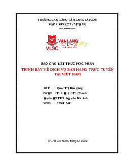
There are two types of airports—towered and nontowered. Nontowered airport traffic patterns are always entered at
These types can be further subdivided to:
pattern altitude. How you enter the pattern depends upon the
direction of arrival. The preferred method for entering from •
Civil Airports—airports that are open to the general
the downwind side of the pattern is to approach the pattern public.
on a course 45 degrees to the downwind leg and join the •
Military/Federal Government airports—airports pattern at midfield.
operated by the military, National Aeronautics and
Space Administration (NASA), or other agencies of
There are several ways to enter the pattern if you’re coming the Federal Government.
from the upwind leg side of the airport. One method of entry •
Private Airports—airports designated for private or
from the opposite side of the pattern is to announce your
restricted use only, not open to the general public.
intentions and cross over midfield at least 500 feet above 14-2
Communication/Broadcast Procedures Facility at Airport Frequency Use Practice Instrument Outbound Inbound Approach UNICOM Communicate with UNICOM Before taxiing and 10 miles out. (no tower or FSS) station on published CTAF before taxiing on the Entering downwind,
frequency (122.7, 122.8, 122.725, runway for departure. base, and final.
122.975, or 123.0). If unable to Leaving the runway.
contact UNICOM station, use self- announce procedures on CTAF. No tower, FSS, Self-announce on MULTICOM Before taxiing and 10 miles out. Departing final or UNICOM frequency 122.9. before taxiing on the Entering downwind, approach fix (name) runway for departure. base, and final. or on final approach Leaving the runway. segment inbound. No tower in Communicate with FSS on CTAF Before taxiing and 10 miles out. Approach operation, FSS open frequency. before taxiing on the Entering downwind, completed/terminated. runway for departure. base, and final. Leaving the runway. FSS closed Self-announce on CTAF. Before taxiing and 10 miles out. (no tower) before taxiing on the Entering downwind, runway for departure. base, and final. Leaving the runway. Tower or FSS Self-announce on CTAF. Before taxiing and 10 miles out. not in operation before taxiing on the Entering downwind, runway for departure. base, and final. Leaving the runway.
Figure 14-1. Recommended communication procedures.
pattern altitude (normally 1,500 feet AGL.) However, if large or pilot with information, such as communication frequencies,
turbine aircraft operate at your airport, it is best to remain 2,000 services available, closed runways, or airport construction.
feet AGL so you are not in conflict with their traffic pattern. Three common sources of information are:
When well clear of the pattern—approximately 2 miles–scan • Aeronautical Charts
carefully for traffic, descend to pattern altitude, then turn right
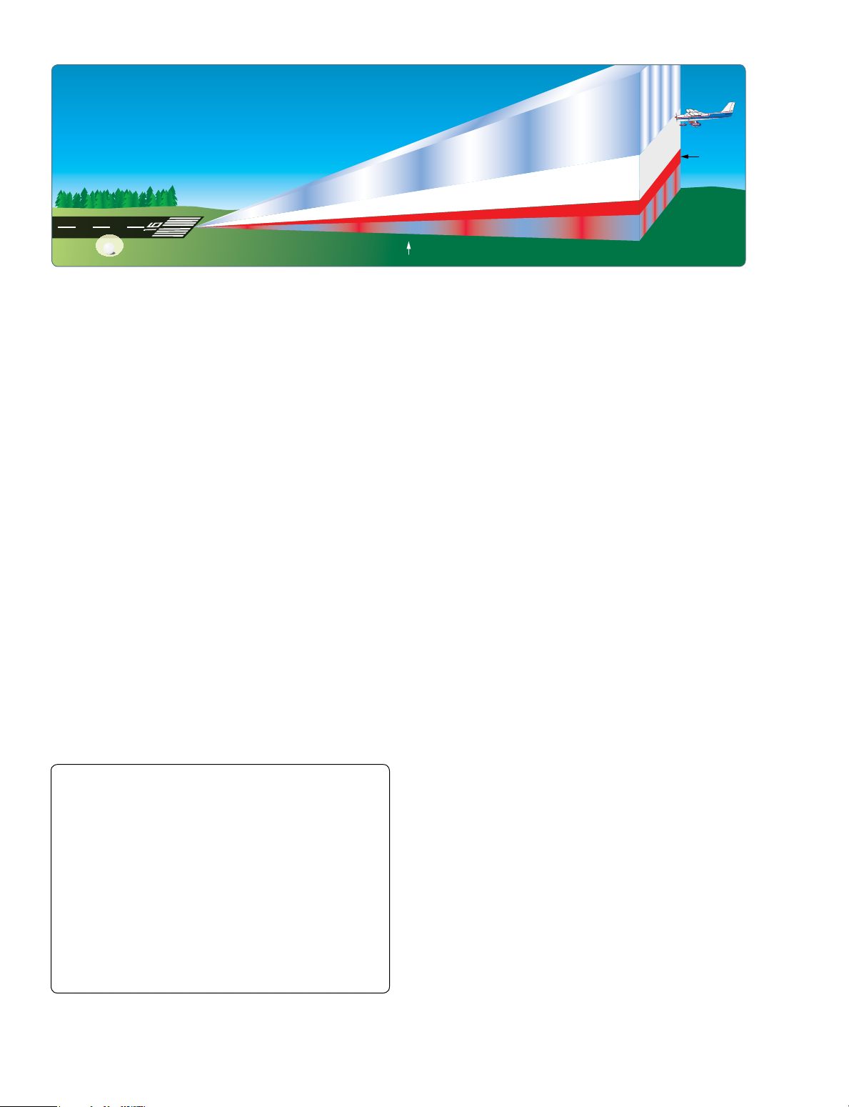
to enter at 45° to the downwind leg at midfield. [Figure 14-2] •
Chart Supplement U.S. (formerly Airport/Facility Directory)
An alternate method is to enter on a midfield crosswind at • Notices to Airmen (NOTAMs)
pattern altitude, carefully scan for traffic, announce your
intentions, and then turn downwind. [Figure 14-3] This •
Automated Terminal Information Service (ATIS)
technique should not be used if the pattern is busy. Always
remember to give way to aircraft on the preferred 45° entry Aeronautical Charts
and to aircraft already established on downwind.
Aeronautical charts provide specific information on airports.
Chapter 16, “Navigation,” contains an excerpt from an
In either case, it is vital to announce your intentions, and aeronautical chart and an aeronautical chart legend, which
remember to scan outside. Before joining the downwind provides guidance on interpreting the information on the chart.
leg, adjust your course or speed to blend into the traffic.
Adjust power on the downwind leg, or sooner, to fit into Chart Supplement U.S. (formerly Airport/Facility
the flow of traffic. Avoid flying too fast or too slow. Speeds Directory)
recommended by the airplane manufacturer should be used. The Chart Supplement U.S. (formerly Airport/Facility
They will generally fall between 70 to 80 knots for fixed-gear Directory) provides the most comprehensive information on
singles and 80 to 90 knots for high-performance retractable.
a given airport. It contains information on airports, heliports,
and seaplane bases that are open to the public. The Chart
Sources for Airport Data
Supplement U.S. is published in seven books, which are
organized by regions and are revised every 56 days. The
When a pilot flies into a different airport, it is important to Chart Supplement U.S. is also available digitally at www.faa.
review the current data for that airport. This data provides the 14-3
Figure 14-2. Preferred Entry-Crossing Midfield.
Figure 14-3. Alternate Midfield Entry.
gov/air_traffic/flight_info/aeronav. Figure 14-4 contains an
excerpt from a directory. For a complete listing of information
provided in a Chart Supplement U.S. and how the information
may be decoded, refer to the “Legend Sample” located in the
front of each Chart Supplement U.S.
In addition to airport information, each Chart Supplement
U.S. contains information such as special notices, Federal
Aviation Administration (FAA) and National Weather
Service (NWS) telephone numbers, preferred instrument
flight rules (IFR) routing, visual flight rules (VFR) waypoints,
a listing of very high frequency (VHF) omnidirectional range
(VOR) receiver checkpoints, aeronautical chart bulletins, land
and hold short operations (LAHSO) for selected airports,
airport diagrams for selected towered airports, en route
flight advisory service (EFAS) outlets, parachute jumping
areas, and facility telephone numbers. It is beneficial to
review a Chart Supplement U.S. to become familiar with the information it contains. Notices to Airmen (NOTAM)
Time-critical aeronautical information, which is of a temporary
nature or not sufficiently known in advance to permit
publication, on aeronautical charts or in other operational Figure 14-4. Chart Supplement U.S. (formerly Airport/Facility Directory excerpt. 14-4
publications receives immediate dissemination by the “Aeronautical Lighting and Other Airport Visual Aids,” of
NOTAM system. The NOTAM information could affect your the Aeronautical Information Manual (AIM).
decision to make the flight. It includes such information as
taxiway and runway closures, construction, communications, Runway Markings and Signs
changes in status of navigational aids, and other information Runway markings vary depending on the type of operations
essential to planned en route, terminal, or landing operations. conducted at the airport. A basic VFR runway may only
Exercise good judgment and common sense by carefully have centerline markings and runway numbers. Refer to
regarding the information readily available in NOTAMs.
Appendix C of this publication for an example of the most
common runway markings that are found at airports.
Prior to any flight, pilots should check for any NOTAMs that
could affect their intended flight. For more information on Since aircraft are affected by the wind during takeoffs and
NOTAMs, refer back to Chapter 1, “Pilot and Aeronautical landings, runways are laid out according to the local prevailing Information” section.
winds. Runway numbers are in reference to magnetic north.
Certain airports have two or even three runways laid out in the
Automated Terminal Information Service (ATIS)
same direction. These are referred to as parallel runways and
The Automated Terminal Information Service (ATIS) is a are distinguished by a letter added to the runway number (e.g.,
recording of the local weather conditions and other pertinent runway 36L (left), 36C (center), and 36R (right)).
non-control information broadcast on a local frequency in a
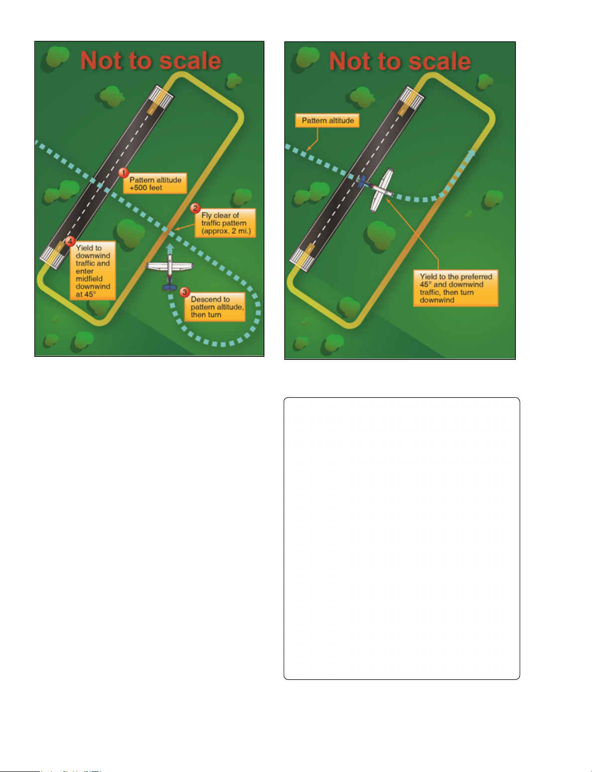
looped format. It is normally updated once per hour but is Relocated Runway Threshold
updated more often when changing local conditions warrant. It is sometimes necessary, due to construction or runway
Important information is broadcast on ATIS including maintenance, to close only a portion of a runway. When
weather, runways in use, specific ATC procedures, and any a portion of a runway is closed, the runway threshold is
airport construction activity that could affect taxi planning.
relocated as necessary. It is referred to as a relocated threshold
and methods for identifying the relocated threshold vary. A
When the ATIS is recorded, it is given a code. This code is common way for the relocated threshold to be marked is
changed with every ATIS update. For example, ATIS Alpha a ten foot wide white bar across the width of the runway.
is replaced by ATIS Bravo. The next hour, ATIS Charlie is [Figure 14-5A and B]
recorded, followed by ATIS Delta and progresses down the alphabet.
When the threshold is relocated, the closed portion of the
runway is not available for use by aircraft for takeoff or
Prior to calling ATC, tune to the ATIS frequency and listen to landing, but it is available for taxi. When a threshold is
the recorded broadcast. The broadcast ends with a statement relocated, it closes not only a set portion of the approach
containing the ATIS code. For example, “Advise on initial end of a runway, but also shortens the length of the opposite
contact, you have information Bravo.” Upon contacting the direction runway. Yellow arrow heads are placed across the
tower controller, state information Bravo was received. This width of the runway just prior to the threshold bar.
allows the tower controller to verify the pilot has the current
local weather and airport information without having to Displaced Threshold
state it all to each pilot who calls. This also clears the tower A displaced threshold is a threshold located at a point on
frequency from being overtaken by the constant relay of the runway other than the designated beginning of the
the same information, which would result without an ATIS runway. Displacement of a threshold reduces the length
broadcast. The use of ATIS broadcasts at departure and arrival of runway available for landings. The portion of runway
airports is not only a sound practice but a wise decision.
behind a displaced threshold is available for takeoffs in either
Airport Markings and Signs
direction, or landings from the opposite direction. A ten feet
wide white threshold bar is located across the width of the
There are markings and signs used at airports that provide runway at the displaced threshold, and white arrows are
directions and assist pilots in airport operations. It is important located along the centerline in the area between the beginning
for you to know the meanings of the signs, markings, and lights of the runway and displaced threshold. White arrow heads
that are used on airports as surface navigational aids. All airport are located across the width of the runway just prior to the
markings are painted on the surface, whereas some signs are threshold bar. [Figure 14-6A and B]
vertical and some are painted on the surface. An overview of the
most common signs and markings are described on the following
pages. Additional information may be found in Chapter 2, 14-5 A B 36
Figure 14-5. (A) Relocated runway threshold drawing. (B) Relocated threshold for Runway 36 at Joplin Regional Airport (JLN).
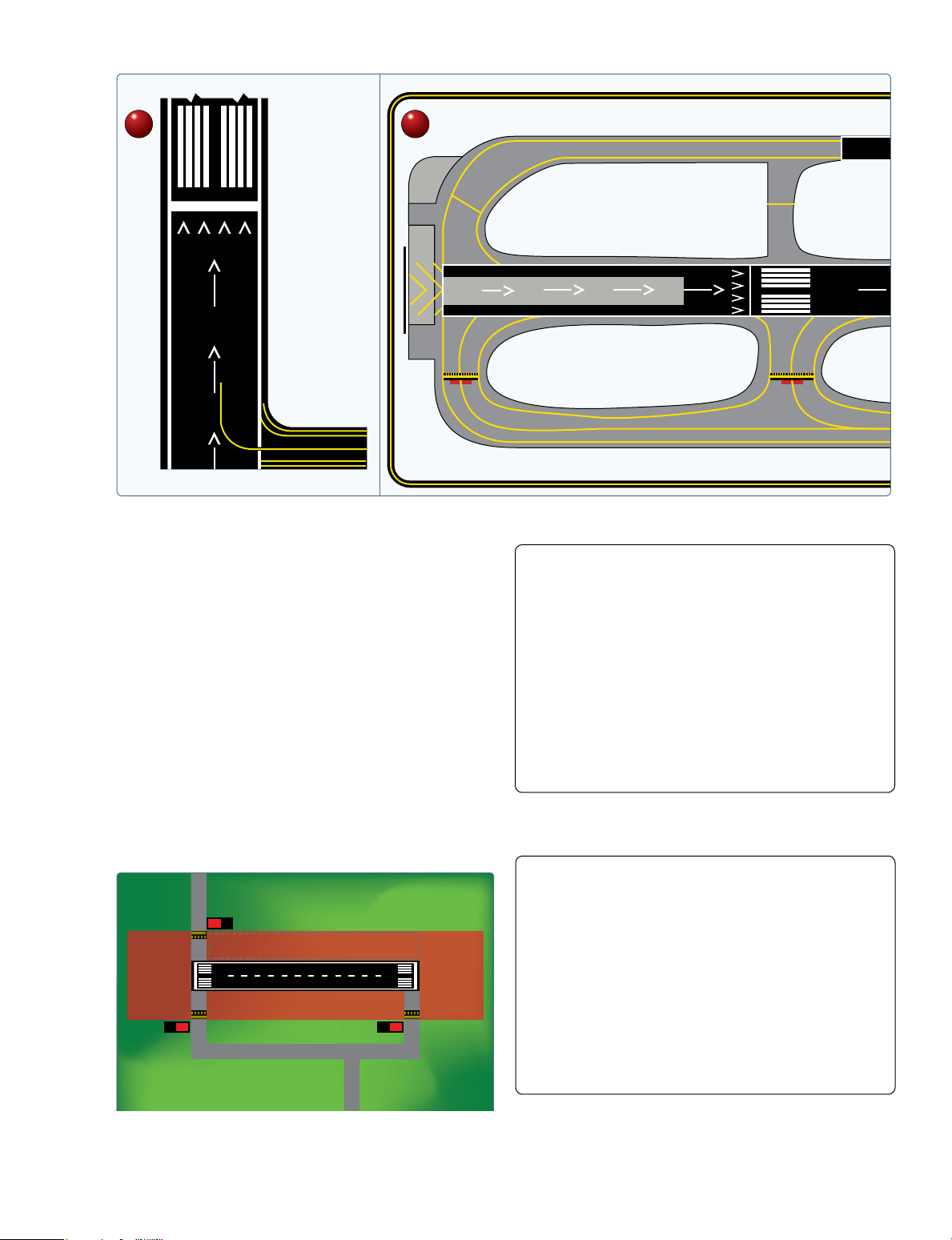
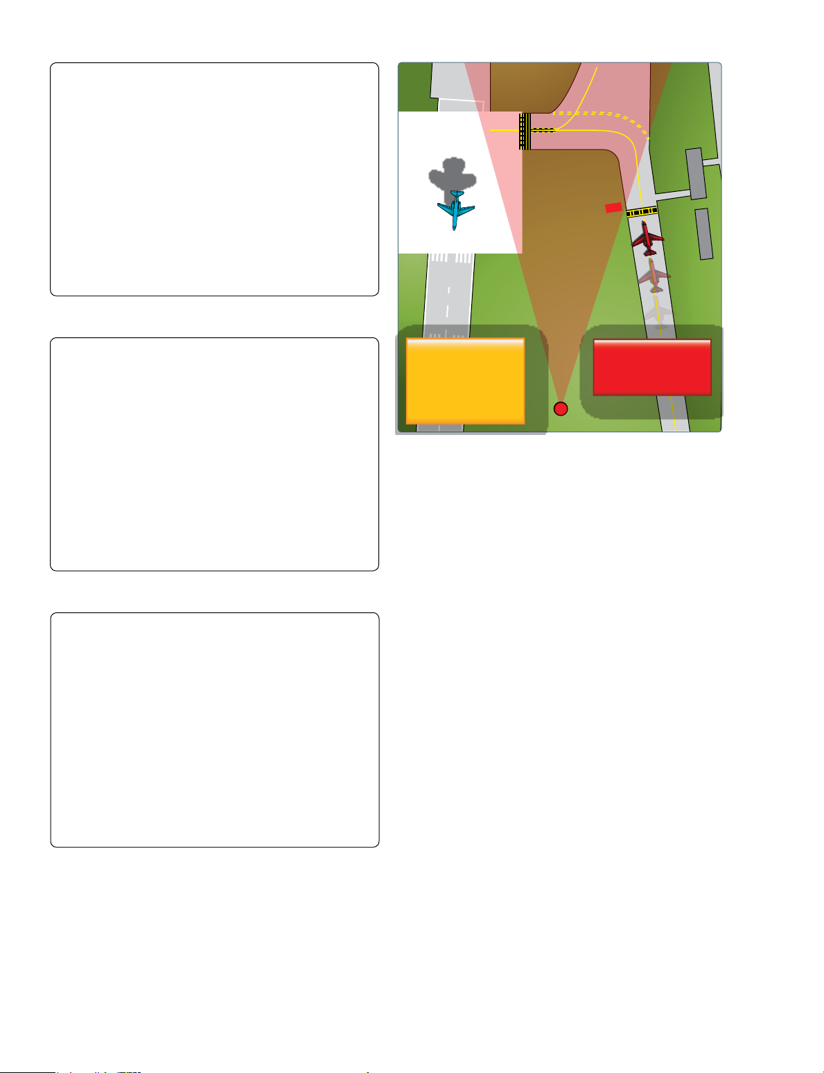
Runway Safety Area
Runway Safety Area Boundary Sign
The runway safety area (RSA) is a defined surface Some taxiway stubs also have a runway safety area boundary
surrounding the runway prepared, or suitable, for reducing sign that faces the runway and is visible to you only when
the risk of damage to airplanes in the event of an undershoot, exiting the runway. This sign has a yellow background with
overshoot, or excursion from the runway. The dimensions black markings and is typically used at towered airports
of the RSA vary and can be determined by using the where a controller commonly requests you to report clear of
criteria contained within AC 150/5300-13, Airport Design, a runway. This sign is intended to provide you with another
Chapter 3. Figure 3-1 in AC 150/5300-13 depicts the RSA. visual cue that is used as a guide to determine when you are
Additionally, it provides greater accessibility for firefighting clear of the runway safety boundary area. The sign shown in
and rescue equipment in emergency situations.
Figure 14-8 is what you would see when exiting the runway at
Taxiway Kilo. You are out of the runway safety area boundary
The RSA is typically graded and mowed. The lateral when the entire aircraft passes the sign and the accompanying
boundaries are usually identified by the presence of the surface painted marking.
runway holding position signs and markings on the adjoining
taxiway stubs. Aircraft should not enter the RSA without Runway Holding Position Sign
making sure of adequate separation from other aircraft during Noncompliance with a runway holding position sign may
operations at uncontrolled airports. [Figure 14-7]
result in the FAA filing a Pilot Deviation against you. A 14-6 A B × × 17
Figure 14-6. (A) Displaced runway threshold drawing. (B) Displaced threshold for Runway 17 at Albuquerque International Airport (ABQ).
runway holding position sign is an airport version of a
stop sign. [Figure 14-9] It may be seen as a sign and/or its
characters painted on the airport pavement. The sign has
white characters outlined in black on a red background. It is
always collocated with the surface painted holding position
markings and is located where taxiways intersect runways.
On taxiways that intersect the threshold of the takeoff runway,
only the designation of the runway may appear on the sign.
If a taxiway intersects a runway somewhere other than at
the threshold, the sign has the designation of the intersecting
runway. The runway numbers on the sign are arranged to
correspond to the relative location of the respective runway Figure 14-8. Runway safety area boundary sign and marking located
thresholds. Figure 14-10 shows “18-36” to indicate the on Taxiway Kilo.
threshold for Runway 18 is to the left and the threshold for 9 C Typical Runway Safety Area 9 27 A 9 B 27
Figure 14-9. Runway holding position sign at takeoff end of Runway
Figure 14-7. Runway Safety Area.
14 with collocated Taxiway Alpha location sign. 14-7
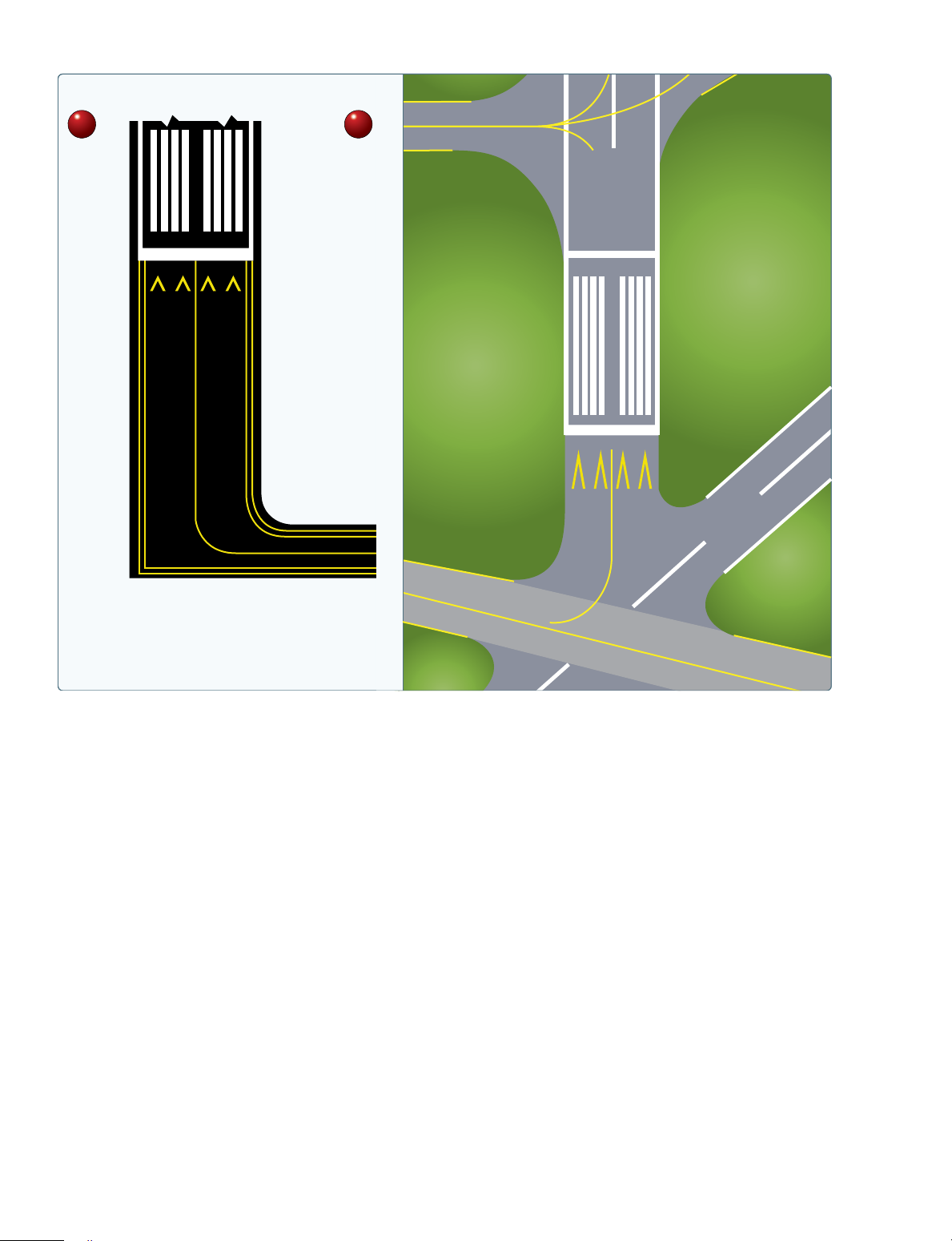
Runway Holding Position Marking
Noncompliance with a runway holding position marking
may result in the FAA filing a Pilot Deviation against you.
Runway holding position markings consist of four yellow
lines, two solid and two dashed, that are painted on the surface
and extend across the width of the taxiway to indicate where
the aircraft should stop when approaching a runway. These
markings are painted across the entire taxiway pavement, are
in alignment, and are collocated with the holding position sign as described above.
Figure 14-10. Runway holding position sign at a location other As you approach the runway, two solid yellow lines and two
than the takeoff end of Runway 18-36 with collocated Taxiway dashed lines will be visible. Prior to reaching the solid lines, it Alpha location sign.
is imperative to stop and ensure that no portion of the aircraft
intersects the first solid yellow line. Do not cross the double
Runway 36 is to the right. The sign also indicates that you solid lines until a clearance from ATC has been received. are located on Taxiway Alpha.
[Figure 14-13] When the tower is closed or when operating at
a nontowered airport, you may taxi onto or across the runway
If the runway holding position sign is located on a taxiway only when the runway is clear and there are no aircraft on final
at the intersection of two runways, the designations for approach. You should use extreme caution when crossing or
both runways are shown on the sign along with arrows taxiing onto the runway and always look both ways.
showing the approximate alignment of each runway.
[Figure 14-11A and B] In addition to showing the When exiting the runway, the same markings will be seen
approximate runway alignment, the arrows indicate the except the aircraft will be approaching the double dashed
direction(s) to the threshold of the runway whose designation lines. [Figure 14-14] In order to be clear of the runway, the
is immediately next to each corresponding arrow.
entire aircraft must cross both the dashed and solid lines.
An ATC clearance is not needed to cross this marking when
This type of taxiway and runway/runway intersection exiting the runway.
geometry can be very confusing and create navigational
challenges. Extreme caution must be exercised when taxiing Runway Distance Remaining Signs
onto or crossing this type of intersection. Figure 14-11A and Runway distance remaining signs have a black background
B shows a depiction of a taxiway, runway/runway intersection with a white number and may be installed along one or both
and is also designated as a “hot spot” on the airport diagram. sides of the runway. [Figure 14-15] The number on the
In the example, Taxiway Bravo intersects with two runways, signs indicates the distance, in thousands of feet, of landing
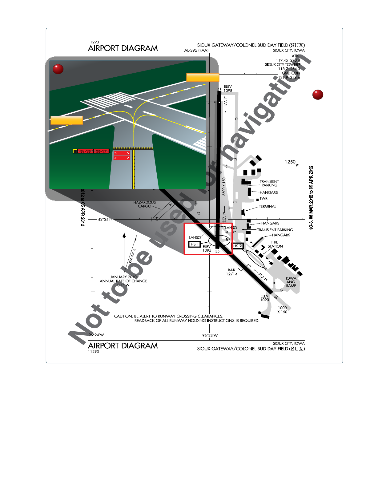
31-13 and 35-17, which cross each other.
runway remaining. The last sign, which has the numeral “1,”
is located at least 950 feet from the runway end.
Surface painted runway holding position signs may also be
used to aid you in determining the holding position. These Runway Designation Marking
markings consist of white characters on a red background
and are painted on the left side of the taxiway centerline. Runway numbers and letters are determined from the
Figure 14-12 shows a surface painted runway holding approach direction. The runway number is the whole number
position sign that is the holding point for Runway 32R-14L. nearest one-tenth the magnetic azimuth of the centerline of the
runway, measured clockwise from the magnetic north. In the
You should never allow any part of your aircraft to cross the case where there are parallel runways, the letters differentiate
runway holding position sign (either a vertical or surface between left (L), right (R), or center (C). [Figure 14-16] For
painted sign) without a clearance from ATC. Doing so poses example, if there are two parallel runways, they would show
a hazard to yourself and others.
the designation number and then either L or R beneath it.
For three parallel runways, the designation number would
When the tower is closed or you are operating at a nontowered be presented with L, C, or R beneath it.
airport, you may taxi past a runway holding position sign only
when the runway is clear of aircraft, and there are no aircraft on
final approach. You may then proceed with extreme caution. 14-8 A Runway 13 3 B Runway 31 5 B 31-13 35-17 35-17 N 31-13 C -3, 08 M 2012 AR 2012 ot 2 to 05 APR 05 201 AP AR R 2012 , 08 M -3 C N
Not to be used for navigation
Figure 14-11. (A) Taxiway Bravo location sign collocated with runway/runway intersection holding signs at Sioux Gateway Airport
(SUX) (B) Airport diagram of Sioux Gateway Airport (SUX), Sioux City, Iowa. The area outlined in red is a designated “hot spot” (HS1). 14-9
Figure 14-12. Surface painted runway holding position signs for
Runway 32R-14L along with the enhanced taxiway centerline marking.
Figure 14-15. Runway distance remaining sign indicating that there
is 2,000 feet of runway remaining.
compliance. As pilot in command (PIC), you have the final
authority to accept or decline any LAHSO clearance.
If issued a land and hold short clearance, you must be aware
of the reduced runway distances and whether or not you can
comply before accepting the clearance. You do not have
to accept a LAHSO clearance. Pilots should only receive a
LAHSO clearance when there is a minimum ceiling of 1,000
feet and 3 statute miles of visibility.
Runway holding position signs and markings are installed
Figure 14-13. Surface painted holding position marking along with
on those runways used for LAHSO. The signs and markings
enhanced taxiway centerline.
are placed at the LAHSO point to aid you in determining
where to stop and hold the aircraft and are located prior to
the runway/runway intersection. [Figure 14-17]
The holding position sign has a white inscription with black
border around the numbers on a red background and is installed
adjacent to the holding position markings. If you accept a land
and hold short clearance, you must comply so that no portion
of the aircraft extends beyond these hold markings.
If receiving “cleared to land” instructions from ATC, you
are authorized to use the entire landing length of the runway
and should disregard any LAHSO holding position markings
located on the runway. If you receive and accept LAHSO
instructions, you must stop short of the intersecting runway
Figure 14-14. Runway holding position markings as seen when prior to the LAHSO signs and markings.
exiting the runway. When exiting the runway, no ATC clearance is required to cross.
Below is a list of items which, if thoroughly understood
and complied with, will ensure that LAHSO operations are
Land and Hold Short Operations (LAHSO) conducted properly.
When simultaneous operations (takeoffs and landings) are •
Know landing distance available.
being conducted on intersecting runways, Land and Hold
Short Operations (LAHSO) may also be in effect. LAHSO
• Be advised by ATC as to why LAHSO are being
is an ATC procedure that may require your participation and conducted. 14-10 35 35 L C
Figure 14-16. Two of three parallel runways. •
Advise ATC if you cannot comply with LAHSO.
If you accept the following clearance from ATC: “Cleared to •
Know what signs and markings are at the LAHSO point.
land Runway 36 hold short of Runway 23,” you must either exit
Runway 36 or stop at the holding position prior to Runway 23. •
LAHSO are not authorized for student pilots who are performing a solo flight.
Taxiway Markings and Signs •
At many airports air carrier aircraft are not authorized Taxiway direction signs have a yellow background and
to participate in LAHSO if the other aircraft is a
black characters, which identifies the designation or general aviation aircraft.
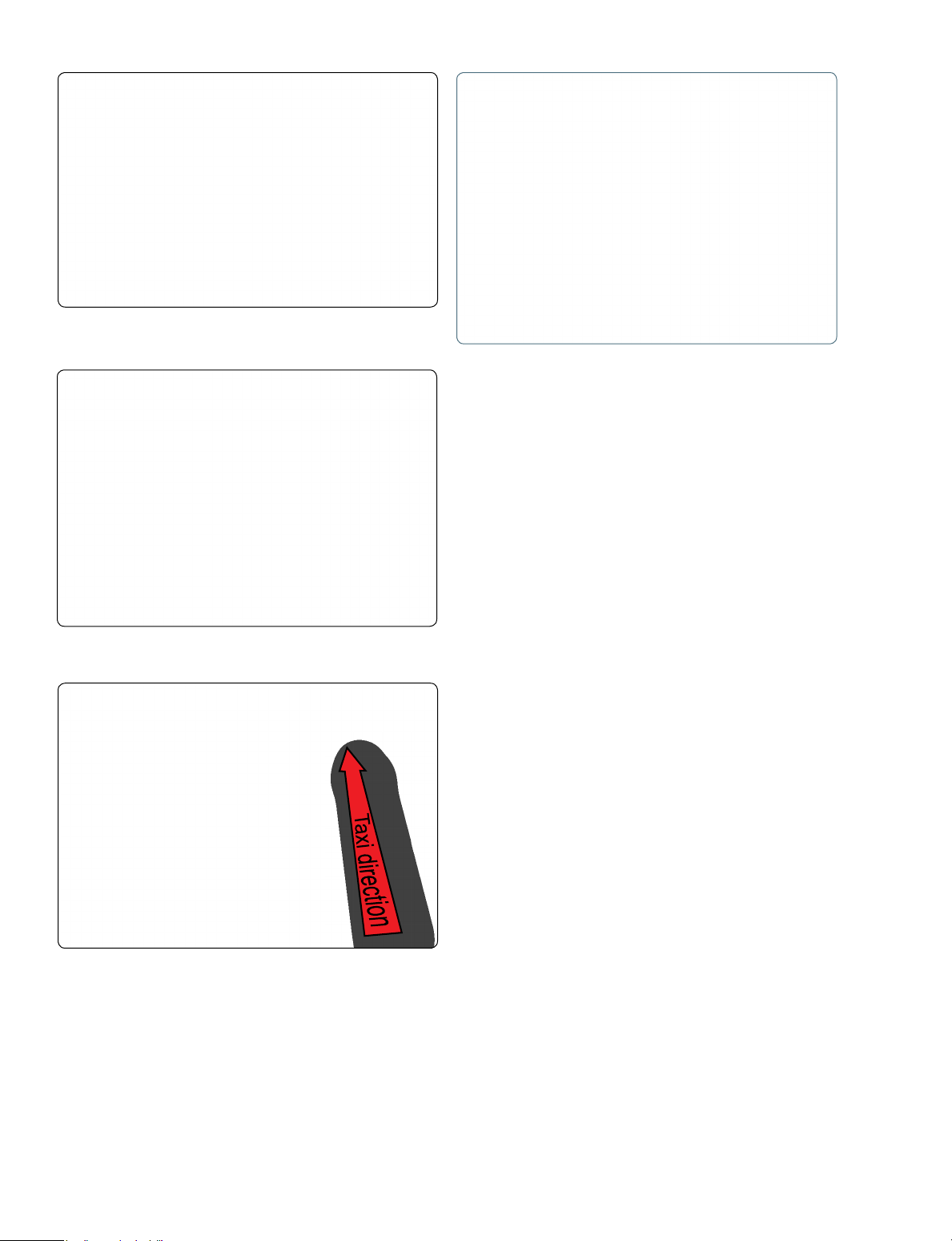
intersecting taxiways. Arrows indicate the direction of turn •
Generally, LAHSO are not authorized at night.
that would place the aircraft on the designated taxiway.
[Figure 14-18] Direction signs are normally located on •
LAHSO are not authorized on wet runways.
the left side of the taxiway and prior to the intersection.
These signs and markings (with a yellow background and
black characters) indicate the direction toward a different
taxiway, leading off a runway, or out of an intersection.
Figure 14-18 shows Taxiway Delta and how Taxiway Bravo
intersects ahead at 90° both left and right.
Taxiway direction signs can also be displayed as surface
painted markings. Figure 14-19 shows Taxiway Bravo as
proceeding straight ahead while Taxiway Alpha turns to the right at approximately 45°.
Figure 14-17. Runway holding position sign and marking for LAHSO. 14-11
signs always have an arrow showing the direction of the taxi
route to that destination. [Figure 14-22] When the arrow on
the destination sign indicates a turn, the sign is located prior
to the intersection. Destinations commonly shown on these
types of signs include runways, aprons, terminals, military
areas, civil aviation areas, cargo areas, international areas,
and fixed-base operators. When the inscription for two or
more destinations having a common taxi route are placed
on a sign, the destinations are separated by a “dot” (•) and
one arrow would be used as shown in Figure 14-22. When
the inscription on a sign contains two or more destinations
having different taxi routes, each destination is accompanied
by an arrow and separated from the other destination(s) on
the sign with a vertical black message divider as shown in
Figure 14-18. Taxiway Bravo direction sign with a collocated Figure 14-23. The example shown in Figure 14-23 shows
Taxiway Delta location sign. When the arrow on the direction
sign indicates a turn, the sign is located prior to the intersection.
two signs. The sign in the foreground explains that Runway
20 threshold is to the left, and Runways 32, 2, and 14 are to
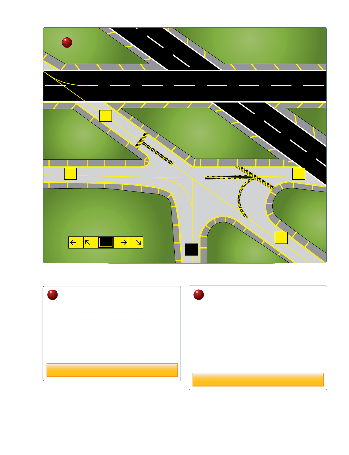
Figure 14-20A and B shows an example of a direction sign at the right. The sign in the background indicates that you are
a complex taxiway intersection. Figure 14-20A and B shows located on Taxiway Bravo and Taxiway November will take
Taxiway Bravo intersects with Taxiway Sierra at 90°, but at you to those runways.
45° with Taxiway Foxtrot. This type of array can be displayed
with or without the taxiway location sign, which in this case Holding Position Signs and Markings for an
would be Taxiway Bravo.
Instrument Landing System (ILS) Critical Area
The instrument landing system (ILS) broadcasts signals to
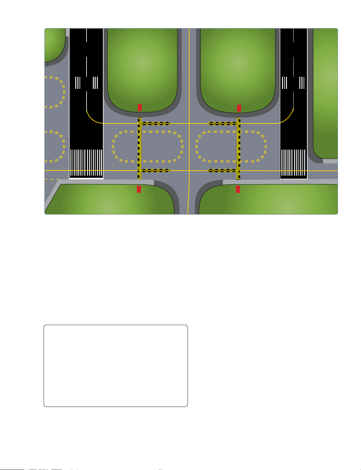
Enhanced Taxiway Centerline Markings
arriving instrument aircraft to guide them to the runway. Each
At most towered airports, the enhanced taxiway centerline of these ILSs have critical areas that must be kept clear of all
marking is used to warn you of an upcoming runway. It consists obstacles in order to ensure quality of the broadcast signal. At
of yellow dashed lines on either side of the normal solid taxiway many airports, taxiways extend into the ILS critical area. Most
centerline and the dashes extend up to 150 feet prior to a of the time, this is of no concern; however, during times of
runway holding position marking. [Figure 14-21A and B] They poor weather, an aircraft on approach may depend on a good
are used to aid you in maintaining awareness during surface signal quality. When necessary, ATC will protect the ILS
movement to reduce runway incursions.
critical area for arrival instrument traffic by instructing taxiing
aircraft to “hold short” of Runway (XX) ILS critical area.
Destination Signs
The ILS critical area hold sign has white characters, outlined
Destination signs have black characters on a yellow in black, on a red background and is installed adjacent to the
background indicating a destination at the airport. These ILS holding position markings. [Figure 14-24] The holding
position markings for the ILS critical area appear on the
pavement as a horizontal yellow ladder extending across the width of the taxiway.
When instructed to “hold short of Runway (XX) ILS critical
area,” you must ensure no portion of the aircraft extends
beyond these markings. [Figure 14-25] If ATC does not
instruct you to hold at this point, then you may bypass the ILS
critical area hold position markings and continue with your
taxi. Figure 14-24 shows that the ILS hold sign is located
on Taxiway Golf and the ILS ladder hold position marking is adjacent to the hold sign.
Figure 14-19. Surface painted taxiway direction signs. 14-12 A F S S A F S F B S F B
Figure 14-20. Orientation of signs is from left to right in a clockwise manner. Left turn signs are on the left and right turn on the right.
Enhanced taxiway centerline marking extends 150 feet prior
In this view, the pilot is on Taxiway Bravo.
to a runway holding position marking. Prepare to STOP. A B B
Enhanced taxiway centerline marking extends 150 feet prior
to a runway holding position marking. Prepare to STOP.
Prepare to STOP unless you have been cleared onto or across the runway by ATC. B
Figure 14-21. (A) Enhanced taxiway centerline marking. (B) Enhanced taxiway centerline marking and runway holding position marking. 14-13
Prepare to STOP unless you have been cleared onto or across the runway by ATC. ILS 19
Figure 14-22. Destination sign to the fixed-base operator (FBO). The yellow surface
ILS Critical Area boundary Hold only painted “ladder” when marking and red ILS specifically sign are located instructed by ATC on taxiways where the taxiways intersect the ILS critical area.
Figure 14-25. Holding position sign and marking for instrument
landing system (ILS) critical area boundary.
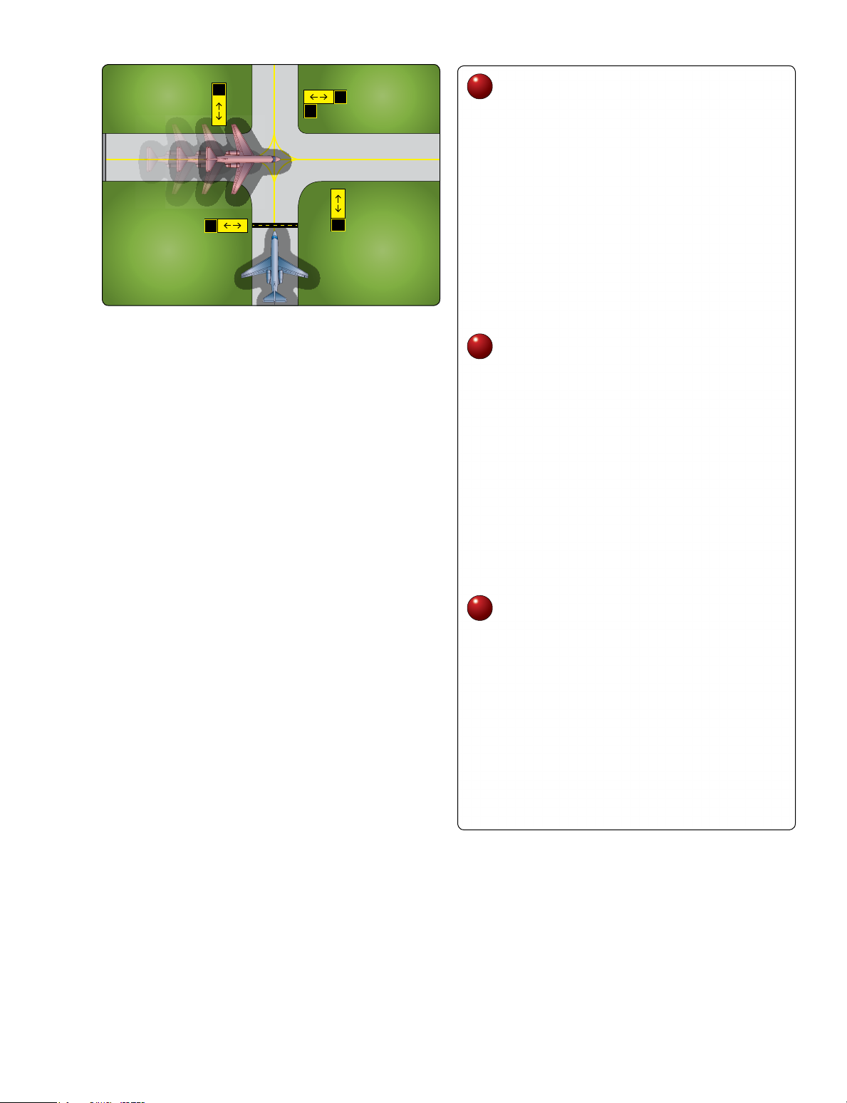
Holding Position Markings for Taxiway/Taxiway Intersections
Holding position markings for taxiway/taxiway intersections
consist of a single dashed yellow line extending across the
width of the taxiway. [Figure 14-26] They are painted on
Figure 14-23. Runway destination sign with different taxi routes.
taxiways where ATC normally holds aircraft short of a
taxiway intersection. When instructed by ATC “hold short
of Taxiway X,” you should stop so that no part of your
aircraft extends beyond the holding position marking. When
the marking is not present, you should stop your aircraft at
a point that provides adequate clearance from an aircraft on the intersecting taxiway.
Marking and Lighting of Permanently Closed Runways and Taxiways
For runways and taxiways that are permanently closed, the
lighting circuits are disconnected. The runway threshold,
runway designation, and touchdown markings are obliterated
and yellow “Xs” are placed at each end of the runway and at 1,000-foot intervals.
Figure 14-24. Instrument landing system (ILS) holding position sign
and marking on Taxiway Golf. 14-14 B B G A G G G G B B
Figure 14-26. Holding position marking on a taxiway. B
Temporarily Closed Runways and Taxiways
For temporarily closed runways and taxiways, a visual
indication is often provided with yellow “Xs” or raised
lighted yellow “Xs” placed at each end of the runway.
Depending on the reason for the closure, duration of closure,
airfield configuration, and the existence and the hours of
operation of an ATC tower, a visual indication may not be
present. As discussed previously in the chapter, you must
always check NOTAMs and ATIS for runway and taxiway closure information.
Figure 14-27A shows an example of a yellow “X” laid flat
with an adequate number of heavy sand bags to keep the
wind from getting under and displacing the vinyl material. C
A very effective and preferable visual aid to depict temporary
closure is the lighted “X” placed on or near the runway
designation numbers. [Figure 14-27B and C] This device is
much more discernible to approaching aircraft than the other materials described above. Other Markings
Some other markings found on the airport include vehicle
roadway markings, VOR receiver checkpoint markings, and
non-movement area boundary markings. Airport Signs
There are six types of signs that may be found at airports. The Figure 14-27. (A) Yellow “X” placed on surface of temporarily closed
runways. (B) Lighted “X” placed on temporarily closed runways.
more complex the layout of an airport, the more important (C) Lighted “X” at night showing a temporarily closed runway.
the signs become to pilots. Appendix C of this publication
shows examples of some signs that are found at most airports, •
Location signs—black with yellow inscription and a
their purpose, and appropriate pilot action. The six types of
yellow border, no arrows. They are used to identify a signs are:
taxiway or runway location, to identify the boundary •
Mandatory instruction signs—red background with
of the runway, or identify an instrument landing
white inscription. These signs denote an entrance to a system (ILS) critical area.
runway, critical area, or prohibited area. 14-15 •
Direction signs—yellow background with black
inscription. The inscription identifies the designation
of the intersecting taxiway(s) leading out of an intersection. White Green White Yellow •
Destination signs—yellow background with black
inscription and arrows. These signs provide information
on locating areas, such as runways, terminals, cargo
areas, and civil aviation areas. •
Information signs—yellow background with black
inscription. These signs are used to provide the pilot
with information on areas that cannot be seen from the
control tower, applicable radio frequencies, and noise Figure 14-28. Airport rotating beacons.
abatement procedures. The airport operator determines
the need, size, and location of these signs.
runway is a precision or nonprecision instrument runway. •
Runway distance remaining signs—black background Some systems include sequenced flashing lights that appear
with white numbers. The numbers indicate the
to the pilot as a ball of light traveling toward the runway at
distance of the remaining runway in thousands of feet.
high speed. Approach lights can also aid pilots operating under VFR at night. Airport Lighting
The majority of airports have some type of lighting for night Visual Glideslope Indicators
operations. The variety and type of lighting systems depends Visual glideslope indicators provide the pilot with glidepath
on the volume and complexity of operations at a given airport. information that can be used for day or night approaches. By
Airport lighting is standardized so that airports use the same maintaining the proper glidepath as provided by the system,
light colors for runways and taxiways.
a pilot should have adequate obstacle clearance and should
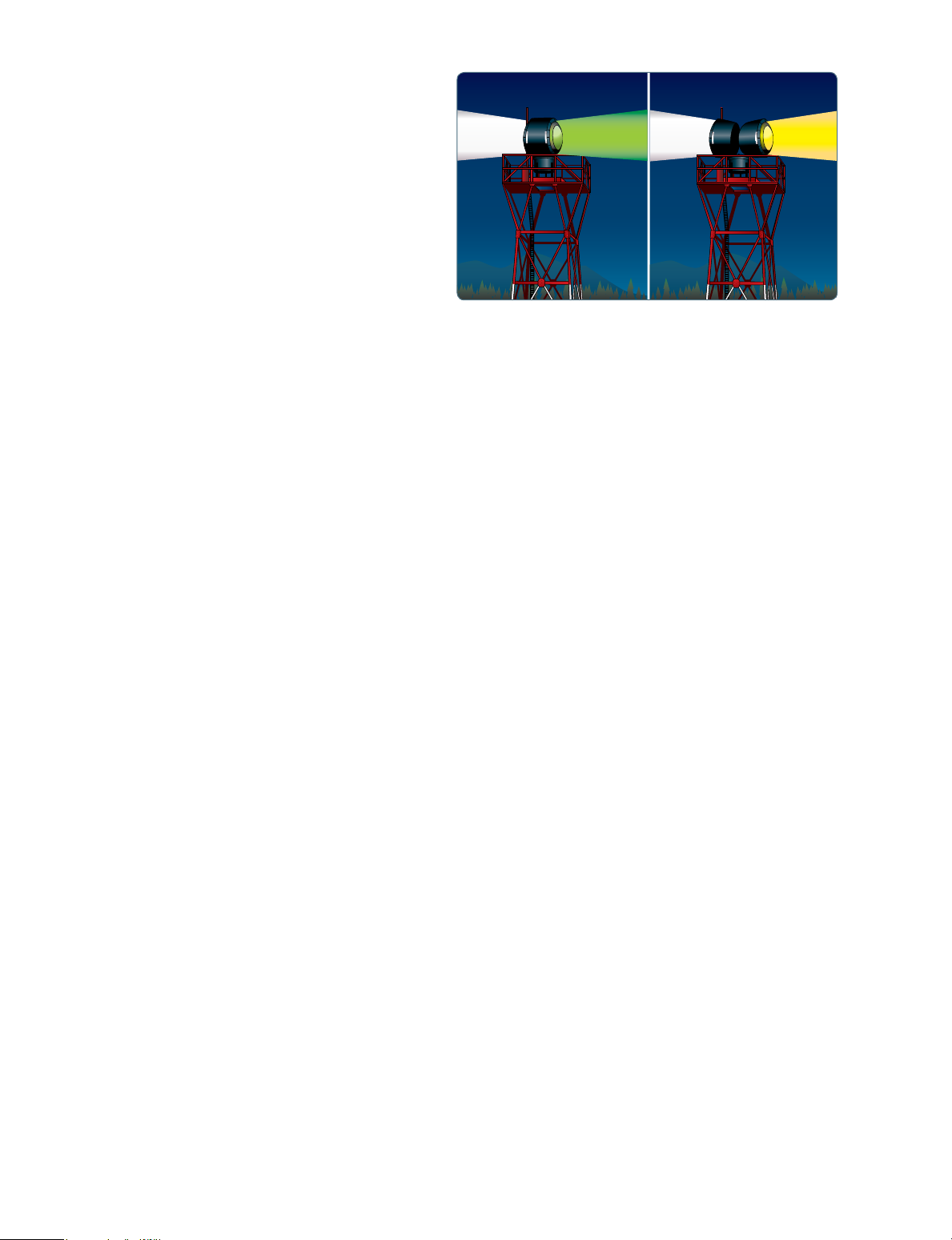
touch down within a specified portion of the runway. Airport Beacon
Airport beacons help a pilot identify an airport at night. Visual Approach Slope Indicator (VASI)
The beacons are normally operated from dusk until dawn. VASI installations are the most common visual glidepath
Sometimes they are turned on if the ceiling is less than 1,000 systems in use. The VASI provides obstruction clearance
feet and/or the ground visibility is less than 3 statute miles (VFR within 10° of the extended runway centerline and up to four
minimums). However, there is no requirement for this, so a nautical miles (NM) from the runway threshold.
pilot has the responsibility of determining if the weather meets
VFR requirements. The beacon has a vertical light distribution The VASI consists of light units arranged in bars. There are
to make it most effective from 1–10° above the horizon, 2-bar and 3-bar VASIs. The 2-bar VASI has near and far light
although it can be seen well above or below this spread. The bars and the 3-bar VASI has near, middle, and far light bars.
beacon may be an omnidirectional capacitor-discharge device, Two-bar VASI installations provide one visual glidepath
or it may rotate at a constant speed, that produces the visual that is normally set at 3°. The 3-bar system provides two
effect of flashes at regular intervals. The combination of light glidepaths, the lower glidepath normally set at 3° and the
colors from an airport beacon indicates the type of airport. upper glidepath ¼ degree above the lower glidepath.
[Figure 14-28] Some of the most common beacons are: •
Flashing white and green for civilian land airports
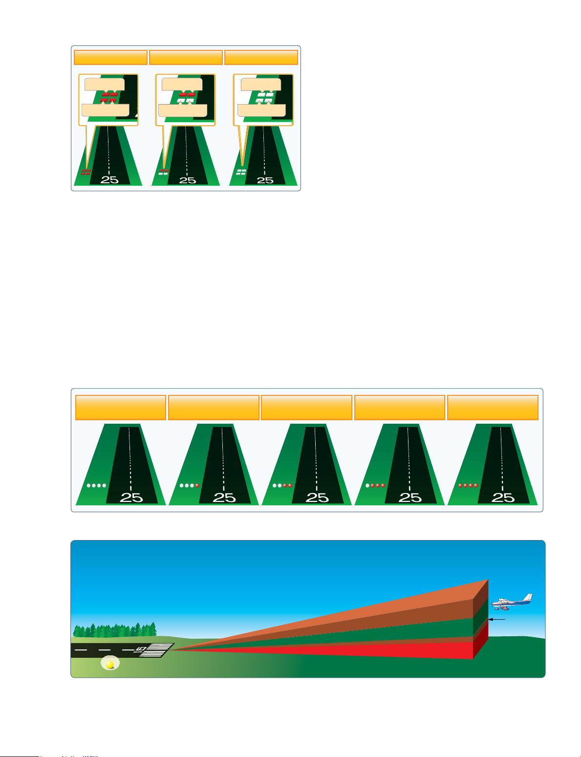
The basic principle of the VASI is that of color differentiation
between red and white. Each light unit projects a beam of •
Flashing white and yellow for a water airport
light, a white segment in the upper part of the beam and a •
Flashing white, yellow, and green for a heliport
red segment in the lower part of the beam. The lights are •
Two quick white flashes alternating with a green flash
arranged so the pilot sees the combination of lights shown in identifying a military airport
Figure 14-29 to indicate below, on, or above the glidepath. Approach Light Systems
Other Glidepath Systems
Approach light systems are primarily intended to provide a A precision approach path indicator (PAPI) uses lights similar
means to transition from instrument flight to visual flight for to the VASI system, except they are installed in a single row,
landing. The system configuration depends on whether the normally on the left side of the runway. [Figure 14-30] 14-16
light. The “slightly below glidepath” indication is a steady red Below Glidepath On Glidepath Above Glidepath
light. If the aircraft descends further below the glidepath, the
red light starts to pulsate. The “above glidepath” indication Far Bar Far Bar Far Bar
is a pulsating white light. The pulsating rate increases as the
aircraft gets further above or below the desired glideslope. Near Bar Near Bar Near Bar
The useful range of the system is about four miles during the
day and up to ten miles at night. [Figure 14-32] Runway Lighting
There are various lights that identify parts of the runway
complex. These assist a pilot in safely making a takeoff or
landing during night operations.
Figure 14-29. Two-bar VASI system.
Runway End Identifier Lights (REIL)
Runway end identifier lights (REIL) are installed at many
A tri-color system consists of a single-light unit projecting airfields to provide rapid and positive identification of the
a three-color visual approach path. Below the glidepath is approach end of a particular runway. The system consists
indicated by red, on the glidepath is indicated by green, and of a pair of synchronized flashing lights located laterally
above the glidepath is indicated by amber. When descending on each side of the runway threshold. REILs may be either
below the glidepath, there is a small area of dark amber. Pilots omnidirectional or unidirectional facing the approach area.
should not mistake this area for an “above the glidepath”
indication. [Figure 14-31] Runway Edge Lights
Runway edge lights are used to outline the edges of
Pulsating VASIs normally consist of a single-light unit runways at night or during low visibility conditions.
projecting a two-color visual approach path into the final [Figure 14-33] These lights are classified according to the
approach area of the runway upon which the indicator is intensity they are capable of producing: high intensity runway
installed. The “on glidepath” indication is a steady white lights (HIRL), medium intensity runway lights (MIRL), and High Slightly High On Glidepath Slightly Low Low more than 3.5° 3.2° 3° 2.8° less than 2.5°
Figure 14-30. Precision approach path indicator for a typical 3° glide slope. Amber Above glidepath Green Amber On glidepath Red Below glidepath
Figure 14-31. Tri-color visual approach slope indicator. 14-17 Pulsating white Above glidepath Steady Steady white red On glidepath
Slightly below glidepath Below glidepath Pulsating red Threshold
Figure 14-32. Pulsating visual approach slope indicator.
low intensity runway lights (LIRL). The HIRL and MIRL Taxiway centerline lead-off lights—provide visual guidance
have variable intensity settings. These lights are white, except to persons exiting the runway. They are color-coded to warn
on instrument runways where amber lights are used on the pilots and vehicle drivers that they are within the runway
last 2,000 feet or half the length of the runway, whichever environment or ILS critical area, whichever is more restrictive.
is less. The lights marking the end of the runway are red.
Alternate green and yellow lights are installed, beginning
with green, from the runway centerline to one centerline light
In-Runway Lighting
position beyond the runway holding position or ILS critical
Runway centerline lighting system (RCLS)—installed on some area holding position.
precision approach runways to facilitate landing under adverse
visibility conditions. They are located along the runway Taxiway centerline lead-on lights—provide visual guidance
centerline and are spaced at 50-foot intervals. When viewed to persons entering the runway. These “lead-on” lights are
from the landing threshold, the runway centerline lights are also color-coded with the same color pattern as lead-off
white until the last 3,000 feet of the runway. The white lights lights to warn pilots and vehicle drivers that they are within
begin to alternate with red for the next 2,000 feet. For the the runway environment or ILS critical area, whichever is
remaining 1,000 feet of the runway, all centerline lights are red. more conservative. The fixtures used for lead-on lights are
bidirectional (i.e., one side emits light for the lead-on function
Touchdown zone lights (TDZL)—installed on some precision while the other side emits light for the lead-off function). Any
approach runways to indicate the touchdown zone when fixture that emits yellow light for the lead-off function also
landing under adverse visibility conditions. They consist of emits yellow light for the lead-on function.
two rows of transverse light bars disposed symmetrically
about the runway centerline. The system consists of steady-
Land and hold short lights—used to indicate the hold short
burning white lights that start 100 feet beyond the landing point on certain runways which are approved for LAHSO.
threshold and extend to 3,000 feet beyond the landing Land and hold short lights consist of a row of pulsing white
threshold or to the midpoint of the runway, whichever is less. lights installed across the runway at the hold short point.
Where installed, the lights are on anytime LAHSO is in effect.
These lights are off when LAHSO is not in effect. Control of Airport Lighting
Airport lighting is controlled by ATC at towered airports. At
nontowered airports, the lights may be on a timer, or where an
FSS is located at an airport, the FSS personnel may control the
lighting. A pilot may request various light systems be turned
on or off and also request a specified intensity, if available,
from ATC or FSS personnel. At selected nontowered airports,
the pilot may control the lighting by using the radio. This
is done by selecting a specified frequency and clicking the
radio microphone. [Figure 14-34] For information on pilot
controlled lighting at various airports, refer to the Chart
Supplement U.S. (formerly Airport/Facility Directory).
Figure 14-33. Runway lights. 14-18
red lights on each side. A controlled stop bar is operated in Key Mike Function
conjunction with the taxiway centerline lead-on lights which 7 times within 5 seconds Highest intensity available
extend from the stop bar toward the runway. Following the Medium or lower intensity
ATC clearance to proceed, the stop bar is turned off and the 5 times within 5 seconds (Lower REIL or REIL off)
lead-on lights are turned on. The stop bar and lead-on lights Lowest intensity available 3 times within 5 seconds
are automatically reset by a sensor or backup timer. (Lower REIL or REIL off)
Figure 14-34. Radio controlled runway lighting. Obstruction Lights
Obstructions are marked or lighted to warn pilots of Taxiway Lights
their presence during daytime and nighttime conditions.
Similar to runway lighting, taxiways also have various lights Obstruction lighting can be found both on and off an airport
which help pilots identify areas of the taxiway and any to identify obstructions. They may be marked or lighted in surrounding runways.
any of the following conditions. •
Red obstruction lights—flash or emit a steady red Omnidirectional
color during nighttime operations, and the obstructions
Omnidirectional taxiway lights outline the edges of the
are painted orange and white for daytime operations.
taxiway and are blue in color. At many airports, these •
High intensity white obstruction lights—flash high
edge lights may have variable intensity settings that may
intensity white lights during the daytime with the
be adjusted by an ATC when deemed necessary or when
intensity reduced for nighttime.
requested by the pilot. Some airports also have taxiway •
Dual lighting—a combination of flashing red beacons
centerline lights that are green in color.
and steady red lights for nighttime operation and high
Clearance Bar Lights
intensity white lights for daytime operations.
Clearance bar lights are installed at holding positions on New Lighting Technologies
taxiways in order to increase the conspicuity of the holding A top priority of the FAA is to continue to enhance airport
position in low visibility conditions. They may also be safety while maintaining airport capacity. Reducing runway
installed to indicate the location of an intersecting taxiway incursions is a major component of this effort. Runway
during periods of darkness. Clearance bars consist of three incursions develop quickly and without warning during routine
in-pavement steady-burning yellow lights.
traffic situations on the airport surface, leaving little time for
corrective action. The Runway Status Lights (RWSL) System
Runway Guard Lights
is designed to provide a direct indication to you that it is unsafe
Runway guard lights are installed at taxiway/runway to enter a runway, cross a runway, or takeoff from or land on
intersections. They are primarily used to enhance the a runway when the system is activated.
conspicuity of taxiway/runway intersections during low
visibility conditions, but may be used in all weather conditions. Runway status lights are red in color and indicate runway
Runway guard lights consist of either a pair of elevated flashing status only; they do not indicate clearance to enter a runway
yellow lights installed on either side of the taxiway, or a row of or clearance to takeoff. The RWSL system provides warning
in-pavement yellow lights installed across the entire taxiway, lights on runways and taxiways, illuminating when it is unsafe
at the runway holding position marking.
to enter, cross, or begin takeoff on a runway. Currently, there
are two types: Runway Entrance Lights (REL) and Takeoff
Note: Some airports may have a row of three or five Hold Lights (THL). [Figures 14-35 and 14-36]
in-pavement yellow lights installed at taxiway/runway
intersections. They should not be confused with clearance REL provide a warning to aircraft crossing or entering a
bar lights described previously in this section.
runway from intersecting taxiways that there is conflicting
traffic on the runway. THL provide a warning signal to Stop Bar Lights
aircraft in position for takeoff that the runway is occupied
Stop bar lights, when installed, are used to confirm the ATC and it is unsafe to take off. As of 2016, the RWSL system is
clearance to enter or cross the active runway in low visibility operational at 14 of the nation’s busiest airports with 3 more
conditions (below 1,200 ft Runway Visual Range (RVR)). airports scheduled to receive the system by 2017.
A stop bar consists of a row of red, unidirectional, steady-
burning in-pavement lights installed across the entire taxiway
at the runway holding position, and elevated steady-burning 14-19
out straighter in strong winds and tends to move back and
forth when the wind is gusting. Wind tees and tetrahedrons
can swing freely and align themselves with the wind direction.
Since a wind tee or tetrahedron can also be manually set to
align with the runway in use, a pilot should also look at the
wind sock for wind information, if one is available. Traffic Patterns
At airports without an operating control tower, a segmented
circle visual indicator system, if installed, is designed to
provide traffic pattern information. [Figure 14-38] Usually
located in a position affording maximum visibility to pilots in
Figure 14-35. Runway Entrance Lights (REL).
the air and on the ground and providing a centralized location
for other elements of the system, the segmented circle consists
of the following components: wind direction indicators,
landing direction indicators, landing strip indicators, and traffic pattern indicators.
A tetrahedron is installed to indicate the direction of landings
and takeoffs when conditions at the airport warrant its use.
It may be located at the center of a segmented circle and
may be lighted for night operations. The small end of the
tetrahedron points in the direction of landing. Pilots are
cautioned against using a tetrahedron for any purpose other
than as an indicator of landing direction. At airports with
Figure 14-36. Takeoff Hold Lights (THL).
control towers, the tetrahedron should only be referenced
Wind Direction Indicators
when the control tower is not in operation. Tower instructions
supersede tetrahedron indications.
It is important for a pilot to know the direction of the wind. At
facilities with an operating control tower, this information is Landing strip indicators are installed in pairs and are used to
provided by ATC. Information may also be provided by FSS show the alignment of landing strips. [Figure 14-38] Traffic
personnel either located at a particular airport or remotely pattern indicators are arranged in pairs in conjunction with
available through a remote communication outlet (RCO), or landing strip indicators and used to indicate the direction of
by requesting information on a CTAF at airports that have the turns when there is a variation from the normal left traffic
capacity to receive and broadcast on this frequency.
pattern. (If there is no segmented circle installed at the airport,
traffic pattern indicators may be installed on or near the end
When none of these services is available, it is possible of the runway.)
to determine wind direction and runway in use by visual
wind indicators. A pilot should check these wind indicators At most airports and military air bases, traffic pattern altitudes
even when information is provided on the CTAF at a given for propeller-driven aircraft generally extend from 600 feet
airport because there is no assurance that the information to as high as 1,500 feet above ground level (AGL). Pilots provided is accurate.
can obtain the traffic pattern altitude for an airport from the
Chart Supplement U.S. (formerly Airport/Facility Directory).
The wind direction indicator can be a wind cone, wind sock, Also, traffic pattern altitudes for military turbojet aircraft
tetrahedron, or wind tee. These are usually located in a central sometimes extend up to 2,500 feet AGL. Therefore, pilots of
location near the runway and may be placed in the center en route aircraft should be constantly on alert for other aircraft
of a segmented circle, which identifies the traffic pattern in traffic patterns and avoid these areas whenever possible.
direction if it is other than the standard left-hand pattern. When operating at an airport, traffic pattern altitudes should
[Figures 14-37 and 14-38]
be maintained unless otherwise required by the applicable
distance from cloud criteria according to Title 14 of the Code
The wind sock is a good source of information since it not of Federal Regulations (14 CFR) part 91, section 91.155.
only indicates wind direction but allows the pilot to estimate Additional information on airport traffic pattern operations
the wind velocity and/or gust factor. The wind sock extends 14-20