Final project on power distribution system môn Hệ thống điện | Trường Đại học Bách Khoa Hà Nội
We have a large number of devices at various power levels and operational stages in the repair shop. To estimate the load effectively, we categorized these machines based on specific criteria. Tài liệu được sưu tầm gồm 24 trang, giúp các bạn ôn luyện và phục vụ cho việc học tập, đạt kết quả tốt. Mời các bạn đón xem!
Môn: Hệ thống điện 14 tài liệu
Trường: Đại học Bách Khoa Hà Nội 5.7 K tài liệu
Tác giả:


Preview text:
HANOI UNIVERSITY OF SCIENCE AND TECHNOLOGY FINAL PROJECT
POWER DISTRIBUTION SYSTEM Trần Quang Anh 20212398 anh.tq212398@sis.hust.edu.vn Instructor: Dr. Lê Việt Tiến School:
Electrical and Electronics Engineering Subject: Power systems Subject code: EE3423E Class: 152312 CONTENTS A.
REQUIREMENT.....................................................................................................3
1. Input data.....................................................................................................................3
2. Duties.............................................................................................................................3
3. Required drawings.......................................................................................................3 B.
CALCULATION AND DESIGN............................................................................4
1. Determine the maximum demands plant...................................................................4
2. Design the medium voltage distribution network of the textile plant......................6
2.1. Problem overview..........................................................................................6
2.2. Select the power supply voltage level for the factory's high-voltage
network.....................................................................................................................7
2.3 Economic Analysis.......................................................................................10
2.4 Equipment selection.....................................................................................12
2.5 Calculated short-circuit to select and test devices.....................................15
2.6 Select diagram for shop substations...........................................................18
C. REFERENCE............................................................................................................24 A. REQUIREMENT
Design the medium voltage distribution system for an industrial plant. 1. Input data
• Plant layout drawing (Fig. 1) and the list of installed demands (Table 1)
Available system voltage levels: 35kV and 22kV.
• Short circuit power at the point of connection to the power system: 250MVA.
• Line feeder to the industrial plant: Overhead line type, aluminum conductor steel
reinforced. Feeder length: 12km.
• Plant’s full load hours: Tmax = 5000 h/year. 2. Duties
• Determine plant’s maximum demand.
• Design the medium voltage distribution system for an industrial plant.
3. Required drawings
Plant’s load layout drawing Single-line diagram of the plant’s MV distribution system.
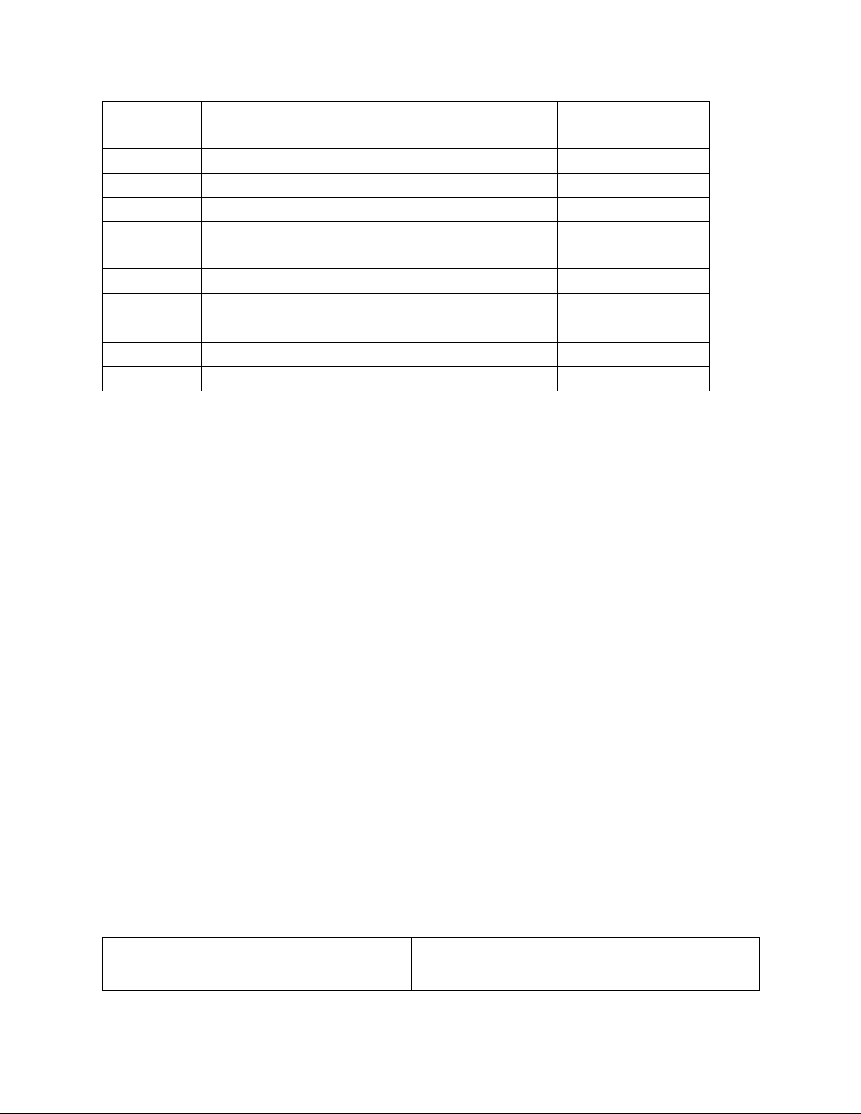
Table 1. Loads specification TT Shop name Installed demand Load criticality (kW) 1 Cotton ginning shop 1400 Vital 2 Textile shop 2500 Vital 3 Dyeing and printing shop 1200 Vital 4 Cleaning and packing 600 Vital shop 5 Repair Shop 200 Normal 6 Wood work shop 150 Normal 7 Pump store 100 Normal 8 Administration building 1500 Normal 9 Warehouse 50 Normal B. CALCULATION AND DESIGN
1. Determine the maximum demands plant
We have a large number of devices at various power levels and operational stages in the
repair shop. To estimate the load effectively, we categorized these machines based on
specific criteria. The categorization follows these regulations:
• Devices within the same group should be located close to one another. This
minimizes the length of the low-voltage network, reducing both investment costs and transmission losses.
• Devices in each group should have similar operational states. This simplifies load
estimation and makes it easier to determine an appropriate power supply method for the group.
• The total power of each group should be roughly equal to reduce the variety of
distribution boards needed. Additionally, the number of devices per group should
remain manageable, typically aligning with the distribution board’s capacity,
which ranges from 8 to 16 outputs Load Calculation
* Estimating shop’s loads Demand Shop name Installed demand Pshop (kW) factor (kW) 0.8 Cotton ginning shop 1400 1120 0.8 Textile shop 2500 2000 0.8 Dyeing and printing shop 1200 960 0.8 Cleaning and packing shop 600 480 0.6 Repair shop 200 120 0.6 Wood work shop 150 90 0.6 Pump shop 100 60 0.6 Administration building 1500 90 0.6 Warehouse 50 30
* Estimating total load of the plant
- Choose diversity factor FD = 0.85 n
Pplant=FD .∑ Pshopi=4207.5kW i=1
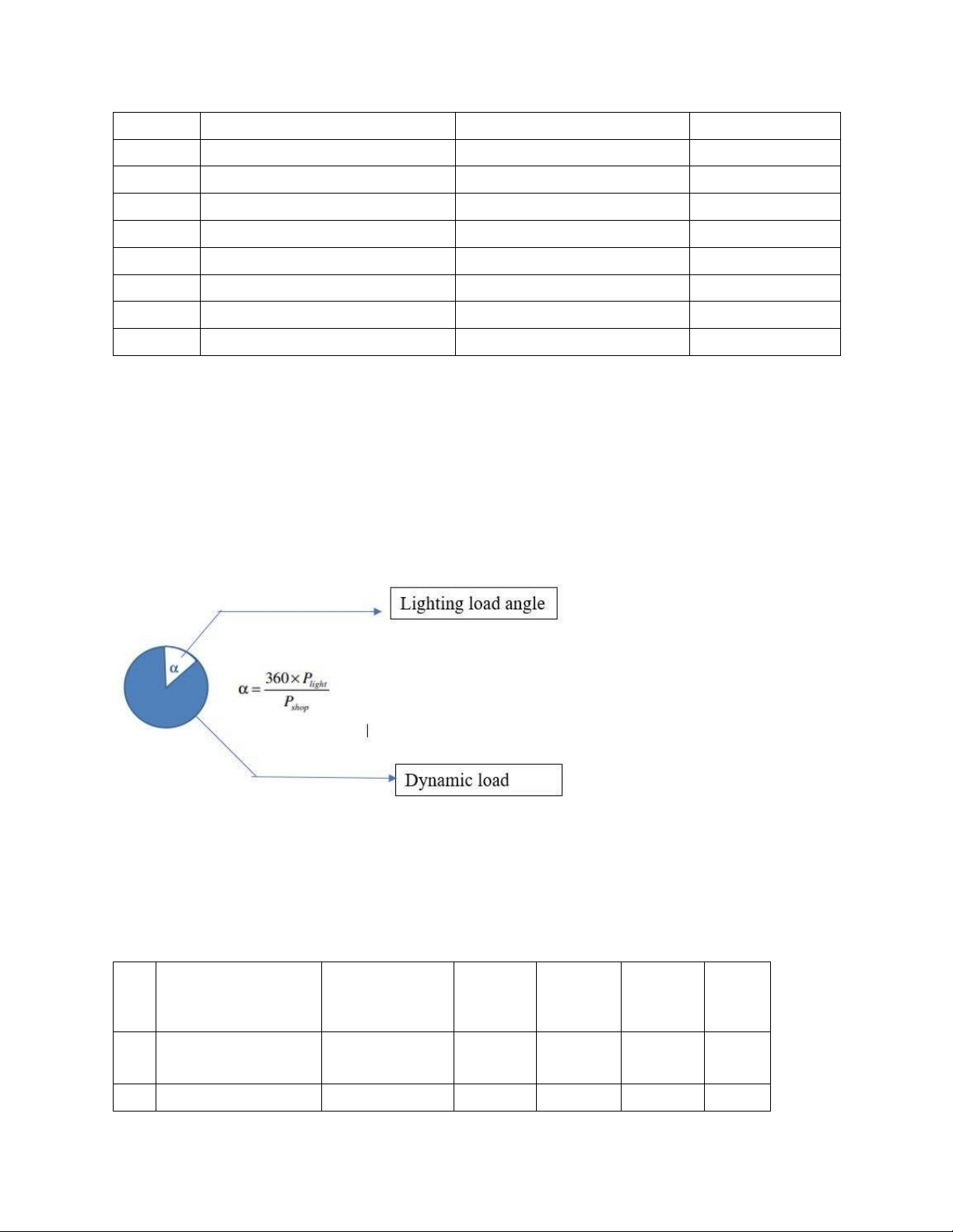
* Estimating load of lighting(Choose σ=20 W/m2)
- Example for calculating in Cotton ginning shop
−Pc=1120kW and Pshop=1120kW
−Demand Area: S=Slayout x 25002=1678.5m2
−Plight=σ .S=20.1678.5=33.57(kW ) => The same calculation with other shops DF Shop name Installed Pshop Plight S α0 cs demand(kW) (kW) (kW) (m2) 0.8 Cotton ginning 1400 1120 33.57 1678.5 10.8 shop 0.8 Textile shop 2500 2000 32.5 1625 5.85 0.8 Dyeing and 1200 960 34.375 1718.75 12.9 prinfting shop 0.8 Cleaning and 600 480 10.3125 515.625 7.73 packing shop 0.6 Repair shop 200 120 6.5 325 19.5 0.6 Wood work shop 150 90 15 750 60 0.6 Pump store 100 60 8.75 437.5 52.5 0.6 Administration 150 90 15.75 787.5 63 building 0.6 Ware house 50 30 16.5 825 198
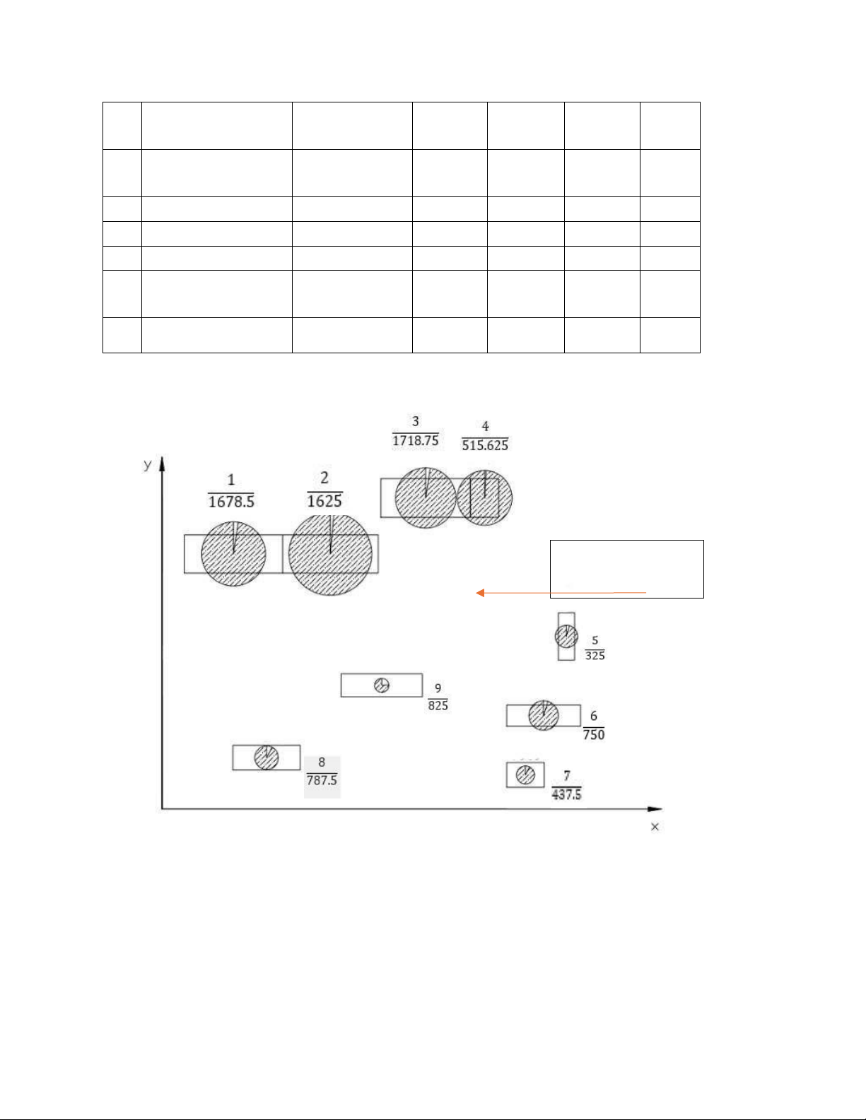
* Plant‘s load layout Stotal=5708 Incoming feeder from power system 2 .
Design the medium voltage distribution network of the textile plant
For design a medium distribution network for the plant, we will follow the this process:
- Give the power supply method
- Choose the quantity, quality, location,type of transformer in substation as well as
the cross-section of wire for that supply method
- Consider about economic and technical aspect to choose the suitable method forpower supply network
- Desgin in detail the power supply method 2.1. Problem overview
The system's economic and technical needs are significantly impacted by the choice
of power supply methods. A power supply plan that was deemed reasonable had to meet the following prerequisites:
- Qualify the technical constraint
- Ensure the reliability of power supply systems
- Convenient and flexible in operation
- Qualify the safety constraint for user and equipment
- Easy to develop to meet the growth of electrical load in future
- Ensuring the economic aspect
In order to design a medium distribution network for the plant, we will follow the this process:
- Estimate the power supply method
- Select the quantity, quality, location,type of transformer in substation as well as
the cross-section of wire for that supply method
- Consider about economic and technical aspect to choose the suitable method forpower supply network
- Design in detail the power supply method
2.2. Select the power supply voltage level for the factory's high-voltage network
Before we came up with the method to supply power, it is necessary to select the suitable
voltage level for the transmission line for area grid to the plant. By using the empirical
equation, we can choose the suitable voltage level:
U = 4,34.√l+0,016.P (kV) Where:
- P is the apperent power demand of the whole plant (kW)
- l is the distant from sources ( middle power substation) to the plant (km) So
the suitable voltage level of the plant is: U = 4,34.
L = 12km, P = 4207.5 kW => U = 38.65 kV
The intermediate substation has voltage levels of (6,10,22,35) kV
So that we will select the 35kV transmission line for the plant
2.2.1 Proposing the power supply diagram of the factory's high-voltage network
Select the power supply scheme from the factory power supply Determine load center: n n n ∑ si xi ∑ si yi ∑ si zi x0=
i=1n ; y0=
i=1n ; z0= i=1n
∑ si ∑ si ∑ si i=1 i=1 i=1
+ x0, y0 ,z0 : load center coordinates
+ xi, yi ,zi : load center coordinates i + s : load capacity i i No. Shop name x y s 1 Cotton ginning shop 37.5 87.5 1274.6 2 Textile shop 70 87.5 2251.2 3 Dyeing and printing shop 102.5 105 1097.6 4 Cleaning and packing shop 122.5 105 542 5 Repair shop 150 72.5 139.2 6 Wood work shop 142.8 45 113.7 7 Pump store 137.5 25 74.6 8 Administration bulding 50 32.5 114.4 9 warehouse 90 57.5 48.7 - x0=¿¿ 489.3 - y0=¿¿ 817.6 = > M(489.3; 817.6)
Choose the workshop substation option
- Method of using intermediate TBA:
Placed at the intermediate substation 2 transformers with selected capacity as follows: Stotal Sdm= 2 = 2854
Check the capacity of the machine when an overload occurs: when a fault occurs in an ap
transformer, we can temporarily stop supplying power to all class III loads in the plant.
Therefore, it is easy to see that the selected transformer satisfies the condition when a fault occurs.
So at the temporary intermediate transformer will place 2 transformers Sdm = 4000kV - 35/10.5 kV.
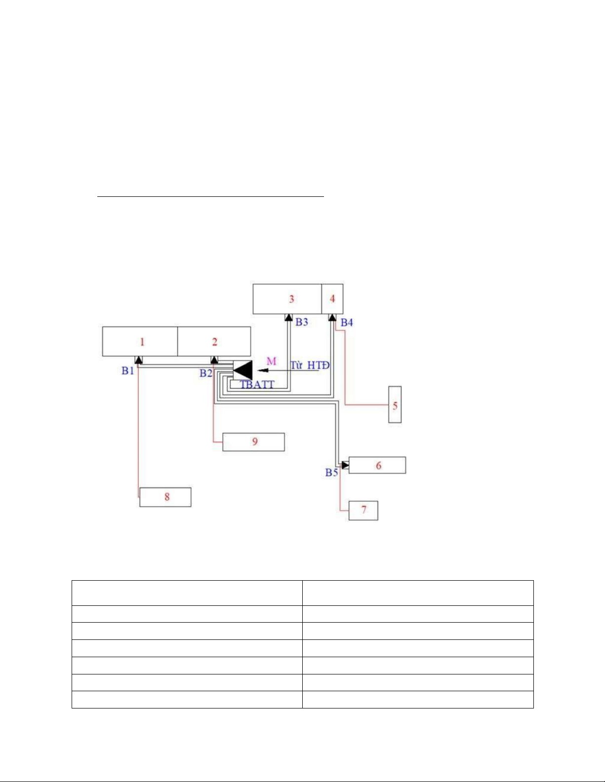
- Method of using central distribution station:
Power from the system is supplied to the workshop substations through the central
distribution station. As a result, the management and operation of the plant's high-voltage
power network is more convenient, the investment capital is reduced, the reliability of
power supply is increased, but the investment capital for the network is also large.
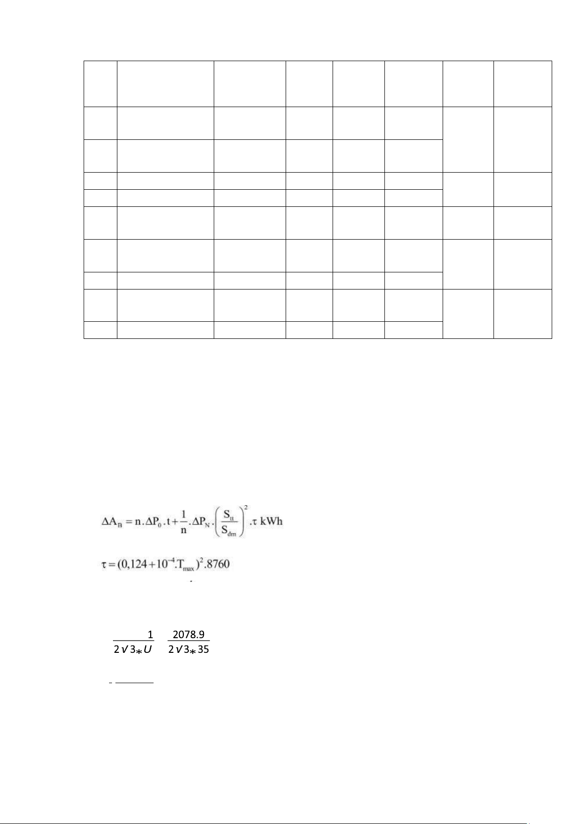
Table 2.2. Distance from stations to workshops Distances(m) TBATT-B1 42.5 TBATT-B2 10 TBATT-B3 53 TBATT-B4 73 TBATT-B5 117.5 B1-PX8 70.5 B2-PX9 53 B4-PX5 63 B5-PX7 15.8 STT Shop name Installed Pshop P light Ptt(KW) Symbol Sttpx demand (kW) (kW) (kW) 1 Cotton ginning 1400 1120 33.57 1153.57 B1 1263.32 shop 8 Administration 150 90 15.75 105.75 building 2 Textile shop 2500 2000 32.5 2032.4 B2 2078.9 9 Ware house 50 30 16.5 46.5 3 Dyeing and 1200 960 34.375 994.375 B3 994.375 prinfting shop 4 Cleaning and 600 480 10.3125 490.3125 B4 616.8125 packing shop 5 Repair shop 200 120 6.5 126.5 6 Wood work 150 90 15 105 B5 173.75 shop 7 Pump store 100 60 8.75 68.75 . 2.3 Economic Analysis
Cross-section of medium voltage cable Choose Tmax = 5200
Using armored copper wire XLPE, Jkt = 2.7
Z=(avh+atc ).K+∆ A .c > MIN
+ Choose avh=0.1+ Choose atc=0.1c: money price for 1kWH drop ∆ A: Voltage drop Drop voltage:
T max¿5200h=¿τ=3633h
- Choose cable from TBATT to B2: SttpxB I lvmax ¿ = = 17.15 ( A) I lvmax 2) Fkt = I kt = 6.35 (mm
We choose XLPE cable with a cross section of 16mm2 and ICp=105A
Check the selected cable cross-section according to the heating condition : 10 KdIcp≥Isc which:
- Isc is the current that occurs when a fault breaks a cable
- Kd is the correction factor according to actual installation conditions, Kd = K1K2
- K1 is the correction factor according to temperature, we take K1=1, K2 is the
correction factor for the number of cables placed in the same cable trench, in low-
voltage networks, two cables are placed in the trenches and the distance between the
wires is 300 mm. K2 = 0.93 Test:
0.93*Icp=97.65(A)>2*Imax=34.30 (satisfy)
Since the distance from TBATT to B2 is small, there is no need to check condition ∆Ucp .
- Choose cable from TBATT to B5: SttpxB I lvmax ¿ = = 1.43 (A ) I lvmax 2) Fkt = I kt = 0.53 (mm
We choose XLPE cable with a cross section of 16mm2 and ICp=105A
Check the selected cable cross-section according to the heating condition : KdIcp≥Isc which:
- Isc is the current that occurs when a fault breaks a cable
- Kd is the correction factor according to actual installation conditions, Kd = K1K2
- K1 is the correction factor according to temperature, we take K1=1, K2 is the
correction factor for the number of cables placed in the same cable trench, in low-
voltage networks, two cables are placed in the trenches and the distance between the
wires is 300 mm. K2 = 0.93 Test:
0.93*Icp=97.65(A)>2*Imax=1.06 (satisfy)
Check condition ∆Ucp: Choose allowable voltage loss of 4% ∆Ucp = = 1400(V)
XLPE cable with a cross section of 16mm2 has x0 = 0.128 Ω/km , r0 = 1.47 Ω /km
The resistance and reactance of the line connecting the TBATT to B5 are: 11
R = r0 *l = 1.47 * 0.1175 = 0.173 Ω
X = x0* l = 0.128 * 0.1175 = 0.015 Ω Thus, the voltage loss on the line is: ∗R +Q∗X ∆U = P Udm =
35 = 0.86 (V) < 1400 (V) (satisfy)
It is the same with other Subtations We have table Branch
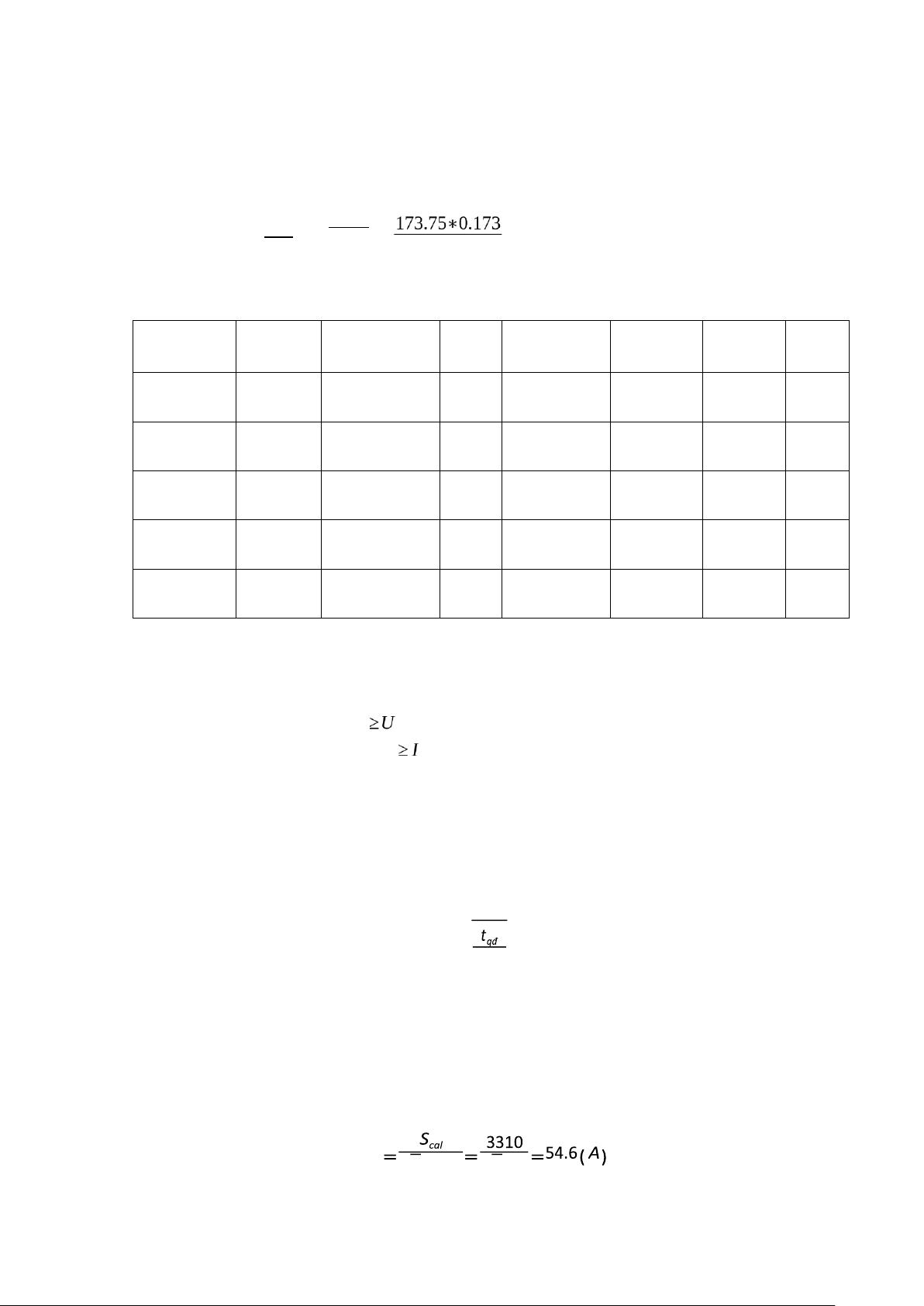
Udm(kV) STBA(kVA) I(A) Ikt(A/mm2) Fkt(mm2) Choose Icp(A) F(mm2) TBATTB1 35 1263.32 10.42 2.7 3.86 16 105 TBATTB2 35 2078.9 17.15 2.7 6.35 16 105 TBATTB3 35 994.375 8.20 2.7 3.04 16 105 TBATTB4 35 616.8125 5.09 2.7 1.89 16 105 TBATTB5 35 173.75 1.43 2.7 0.53 16 105 2.4 Equipment selection 2.4.1 Circuit breaker
Conditions for selecting and checking circuit breaker : - Rated
voltage: U r ated C B ratedLĐ=35 kV - Rated long current: I ratedCB
damping( A) With Idamping is damping current. -
Rated cutting current (kA): I cut. rated ≥ I}} rsub {N ¿¿ -
Rated cutitng voltage (MVA): Scđm ≥S}} rsub {N} ¿¿ -
Dynamic stable current (kA): I d−s ≥ixk - Heat stable current (kA): √ I nhđm≥I∞ tnhđm
When one supply line fails, all of the plant's subcomputing power flows through the
remaining line and the circuit breaker.
The forced current flowing through the circuit breaker is : I cb √3Urated √3.35 12
Opt circuit breaker for outdoor SF6 that made by Schneider has parameters as follows: Type U (kV) (A) (kA) (kA) 1-3s rated I rated I d−s I sc Note 36GI-E25 36 1250 63 25 2.4.2 Bus bar
Busbars are still called busbars or guide bars and are used in distribution cabinets,
lowpressure power cabinets, circuit breaker cabinets, and distribution stations. For
distributors who regularly use software contribution bars. Condition options :
- Select according to the allowable heating current (or according to the economic
current density) and check according to the conditions of dynamic stability and
thermal stability of short-circuit current.
K1 .K2 .I cp ≥ I cb where:
K1 is dependent on bus bar placement. K1=1 if bus bar stands
K1=0,95 if bus bar lies horizontally
K is coefficient that follows enviromental temperature. 2 - Dynamic stability
б al≥бcal б : allowable stress al
б cal: calculated stress under the effect of short-circuit current electromotive force.
Select bus bars manufactured by Siemens with the following parameters: 13 - Size 30x4 (mm)
- Resistance: r0 = 0,167 (mΩ/m)
- Inductance: x = 0,189 (mΩ/m) 0
- Allowable current: I al = 475 (A)
2.4.3 Voltage transformer
A measurement transformer, also known as a voltage transformer (BU ; TU), has the
function of converting any primary power source to 100 or (V) power the
measurement circuit and protects the control signal.
Measurement transformers are made with voltages of 3kV or more, dry or oiled type.
Warehouse voltage transformers are usually placed in the house while voltage
transformers can be placed anywhere. Both types are made single-phase or threephase.
Including 3-phase 5-column BU machine (
) (star 0 star 0 open triangle) In
addition to the normal function, the open triangle coil also has the task of reporting a 1-phase ground fault.
Select BU according to the following conditions: - Wiring diagram - Exact level - Rated power
- Rated voltage : UratedTr ≥UratedLĐ
Select voltage transformer 4MR66 (with two busbars) manufactured by Siemens, parameters : - Rated voltage : 36 kV
- Industrial frequency withstand voltage 1’ : 70 kV
- Pulse withstand voltage 1.2/50μs: 170 kV
- U1rated: 35/√ 3 kV
- U2rated: 100,100//√ 3,100/3 (V) - Rated load: 400 (VA)
2.4.4 Current transformer
Current transformers are used to convert primary currents of any value down to 5A, to
supply current sources for measurement circuits and to protect control signals. Usually
current transformers are manufactured with five levels of accuracy : 0.2; 0.5 ; first ; 3 ;
10. The current transformer symbol is BI.
Conditions for selecting current transformers : • Rated voltage: 36kV
• Voltage to undergo industrial frequency 1’: 70 kV.
• Voltage to undergo pulse 1,2/50μs: 170 kV.
• I 1rated: 20(kA) 14
• I 2rated: 5 A • I ôdn: 80 (kA) I ôdd: 120 (kA)
2.5 Calculated short-circuit to select and test devices
The purpose of short circuit calculation is to check the dynamic and thermal stability
conditions of selected equipment and conductors when there is a short circuit in the
system. The short-circuit current calculated to select electrical equipment is the 3phase
short-circuit current. When calculating the short circuit on the high voltage side, because
we do not know the specific structure of the national power system, we allow an
approximate calculation of the system reactance through the short circuit capacity on the
low voltage side of the middle transformer station and consider system power is so large.
In calculating short circuits in medium voltage grids, we have the following
assumptions to simplify the short circuit calculation process.
• The short circuit is far from the source so the voltage is not reduced.
• Group sources into equivalent sources and equivalent reactances.
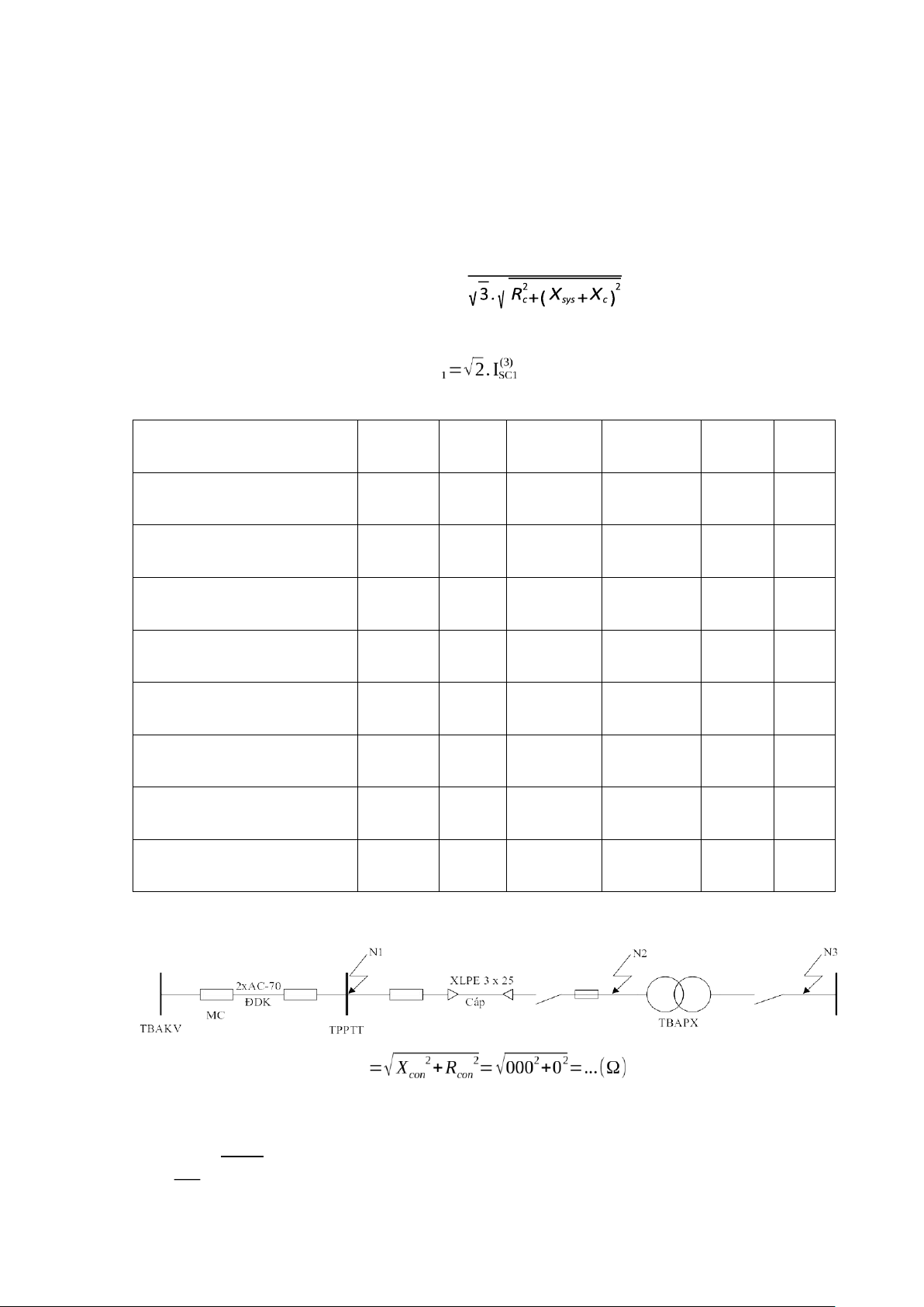
To select and check wires and electrical appliances, it is necessary to calculate 15 short circuit points:
+ N: short-circuit point on bus bar of central distribution station for testing circuit breaker and bus bar.
+ N1 …,N7 : short-circuit point of high voltage of workshop to check cable and high voltage devices of stations.
+N '1 …,N7 ': short-circuit point of step-down voltage side of station to check total aptomat of station.
Inductance of system is defined as: U2tb X sys= SSC Where:
SSC: short-circuit inducity at step-downside of station. Here, we have SSC =400 MVA
Utb=1,05.Uđm=1,05.35=10(kV ) U2tb 36.752 X sys=
SN = 400 =3.376(Ω) 15
Resistance and inductance of conductor:
Rc=r0.l (Ω)
X c=x0 .l(Ω) Three-phase short-circuit is followed by: ( ) Utb I
SC3 = I’’ =I ∞ =
Value of short circuit shock current: ishock .kshock
Parameters of the aluminium conductor steel reinforced and cables L(km Conductor F )
Ro(Ω/km)
X o(Ω/km) R(Ω) X(Ω) Middle transformer 6.04 station-Central Dis.Tr 2AC-35 15 0.85 0.403 12.75 5 0.00 Central -T1 0.056 2(3*16) 1.47 0.128 0.082 7 0.117 1.47 0.128 0.01 Central -T2 2(3*16) 0.172 5 0.057 1.47 0.128 0.00 Central -T34 2(3*16) 0.084 7 0.096 1.47 0.128 0.01 Central -T5 2(3*16) 0.141 2 0.049 1.47 0.128 0.00 Central -T6 2(3*16) 0.072 6 0.065 1.47 0.128 0.00 Central -T79 2(3*16) 0.096 8 0.113 1.47 0.128 0.01 Central -T8 2(3*16) 0.166 4
The wire route transmitting power from the intermediate station to the central
distribution station has been determined as follows : Zcon Reactance of system U2tb 36.752 X sys=
SN = 400 =3.376(Ω) 16
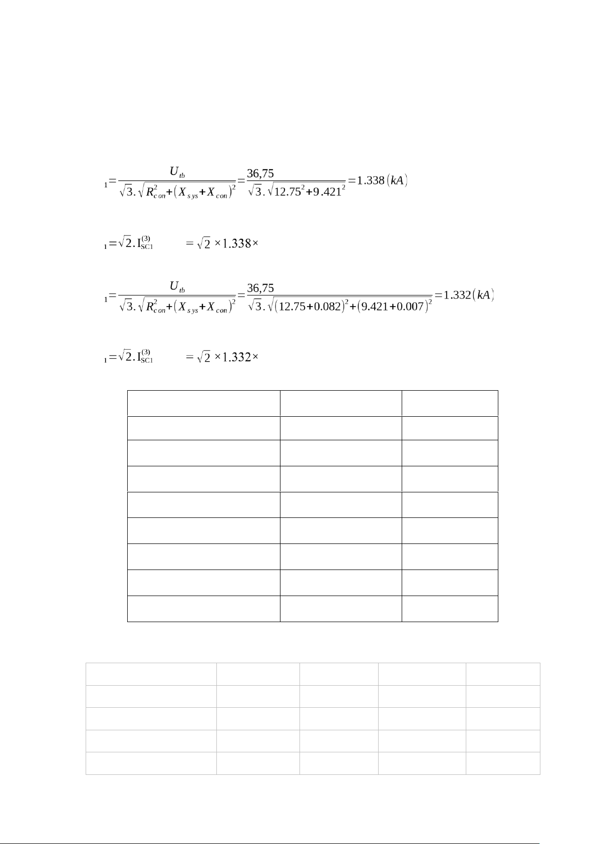
Resistance and reactance at point N:
R=Rcon=r o.l=0,85×15=12.75(Ω)
X=X sys+Xcon=Xsys+xo .l=3.376+6.045=9.421(Ω) Short-circuit current at N: I(SC3)
Value of short circuit shock current: ishock .kshock 1.8 = 3.406 (kA) Short-circuit current at N1: I(SC3)
Value of short circuit shock current: ishock .kshock 1.8 = 3.391 (kA)
- Calculate similarly with points N2 to N7 Short-circuit point I(SC3) (kA) ishock (kA) N 1.338 3.406 N1 1.332 3.391 N2 1.326 3.375 N3 1.322 3.365 N4 1.328 3.380 N5 1.333 3.393 N6 1.331 3.388 N7 1.327 3.378
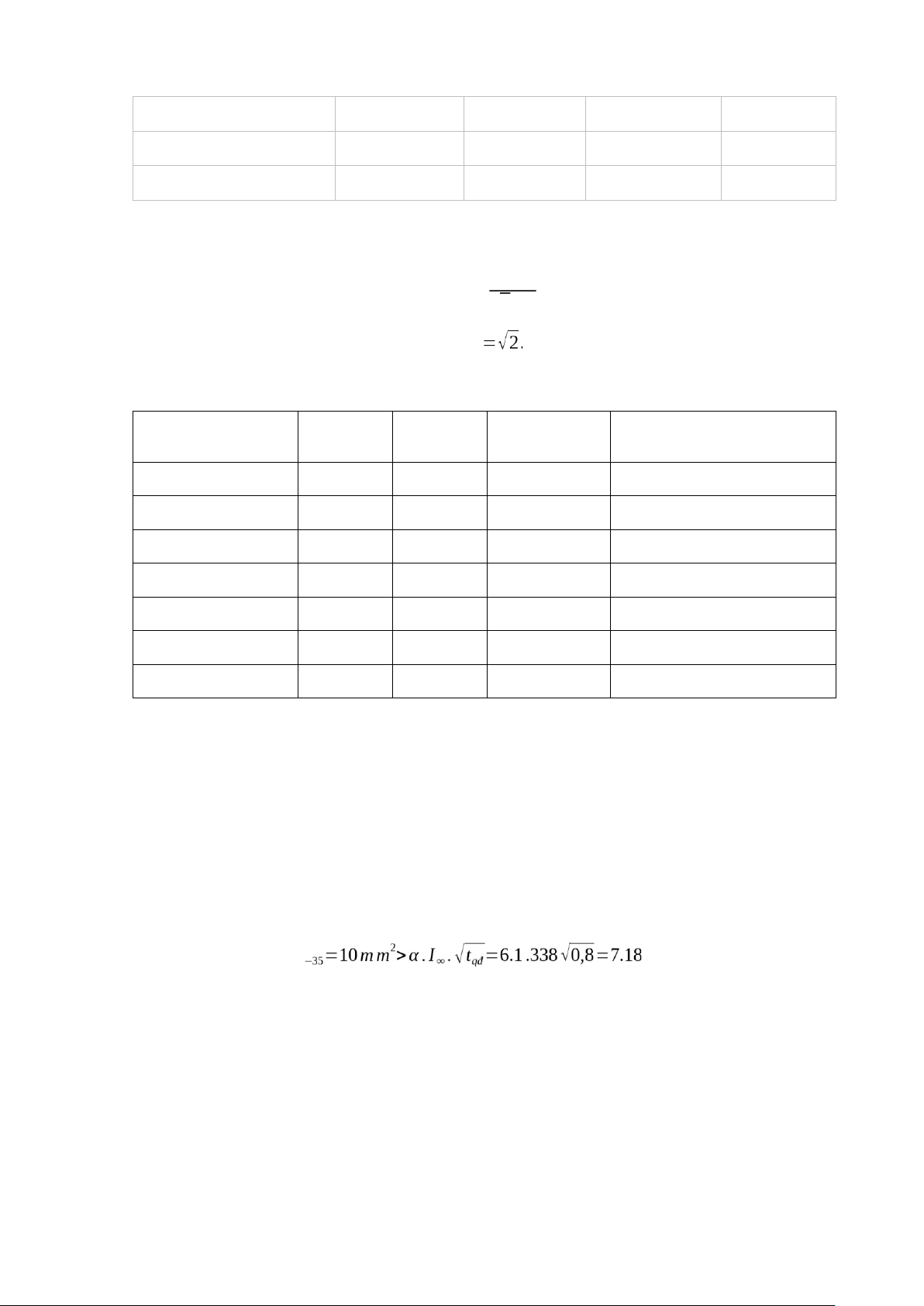
- Calculate the short circuit current at N'1..., N'7
The total impedance of the workshop transformer is referred to the low voltage side Workshop substation ∆ P nl Unl% RTr (mΩ¿ XTr(mΩ¿ T1 10.0 6 0.736 4.8 T2 6.21 4.5 1.44 9.6 T34 10.0 6 1.44 9.6 T5 6.21 4.5 1.44 9.6 17 T6 4.6 4.5 1.44 9.6 T79 7.1 5.5 1.44 9.6 T8 1.75 5 4.46 20
The short circuit current at points N'1, ...N'7 converted to the low voltage side is
calculated according to the formula : U tb I sc= √3. Zi ishock I N .kxk
With U tb=0,4 kV
Value of short-circuit at point N’1…N’7 Short-circuit point R (kA) (kA) Tr(mΩ) XTr(mΩ) I sc ishock N'1 0.736 4.8 47.56 121,07 N'2 1.44 9.6 23.79 60,56 N'3 1.44 9.6 23.79 60,56 N'4 1.44 9.6 23.79 60,56 N'5 1.44 9.6 23.79 60,56 N'6 1.44 9.6 23.79 60,56 N'7 4.46 20 11.27 28,69
- Check the circuit breaker and busbar again.
The 36GI – E25 has cutting current I sc=25kA. Busbar at central distribition station has
dynamic stable current I d−s=63kA is much bettter than short circuit current 1,338 kA and
short circuit shock current 3.406 kA at the short-circuit point of central distribution
station. So the selected circuit breaker and bus bar are accepted. - Check cables:
Just check the cable route with the largest short-circuit current:
Short-circuit current thermal stability conditions: F AC (mm2)
Therefore, choosing cable has 16 mm2 for cables are suit.
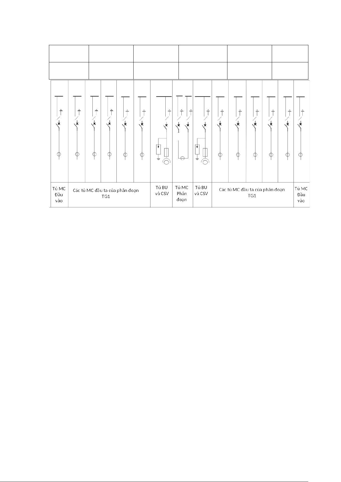
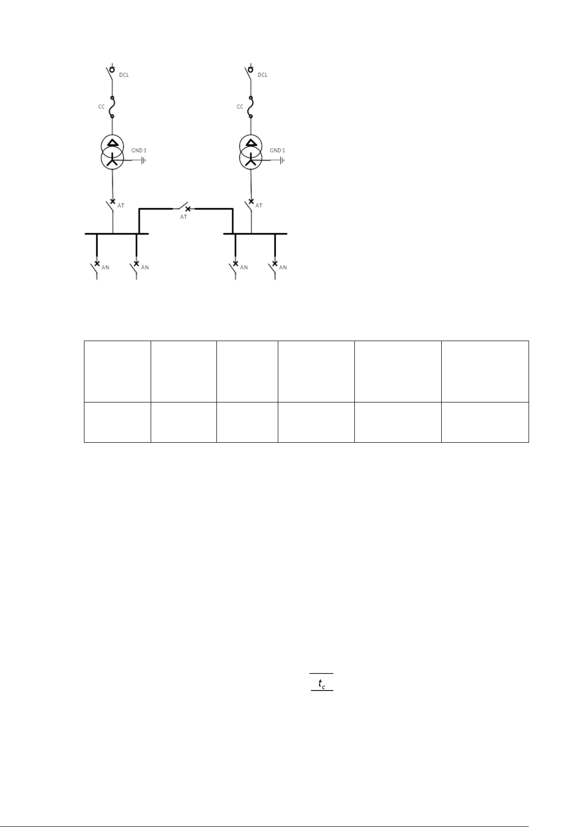
2.6 Select diagram for shop substations
Because the workshop substations are located near the central distribution substation,
the high-voltage side of the substation only needs to place an isolator and fuse. On the
low pressure side, the total circuit breaker and branch circuit breaker are installed. The
low pressure busbar is segmented by segment circuit breaker. To limit the short-circuit
current on the low-voltage side of the station and simplify the selection of protection
methods for the low-voltage busbar segment circuit breaker in the open state. 18 2.6.1 Choose cabinet
Install two 35kV input cabinets with 3-position isolators, SF6 insulation,
maintenancefree, type 8DH10 manufactured by Siemens. Type Urated I đm U I sc allowable −allowable 1s
I stable−dynamic ¿kV) ¿A) (kA) ¿kV) (kA) 8DH10 35 200 25 25 63
2.6.2 Choose disconnecting switch
The disconnecting switch is responsible for isolating the electrical part and the
nonenergetic part, creating a safe distance to be found, serving the work of repairing,
checking and maintaining equipment. In some cases, the switch is allowed to cut a small load current.
For convenience, use the same type of disconnector for all boundary voltage stations
for easy procurement and replacement installation. Knives can be selected according to the following conditions: - Rated voltage: U r ≥Ur−load - Rated current: I r ≥I force
- Stable current is allowable i sta ≥ishock
- Thermal stable current I .√
t−sta ≥ I ∞ − tt sta
The maximum current flowing through the isolator is considered when the transformer
with the largest capacity is overloaded by 40%: 19 I = = cb =17.32 A √3.UTr √3.35
We choose disconnecting switch 3DC that made by SIEMENS Type Urated , kV I rated,A I Nt ,kA iodd, kA 3DC 36 630 20 50
Check disconnecting switch as above conditions, since disconnecting switchs are the
same of type for substation so the parameters are recorded as highest value from point
N1 to N7. Considering bellow table: Parameter Opted value Value calculating checking Ur ≥Ur−load 36 35 I r ≥I force 630 17.32 ista ≥ishock 50 3.406 20 1,338. .√ I = 5.182
t−sta ≥ I ∞ − tt sta
From evaluation of the table, to conclude that current the disconnecting switch is suitable for system.
2.6.3 Choose high voltage fuse
The function of the fuse is to protect against overload and short circuit for power grids
of 35 kV or less. Fuses are often used in the following locations:
• Protects the measurement transformer at all voltage levels.
• Combined with a load fuse to create a load breaker to protect medium voltage lines.
• Placed on the high-pressure side of the distribution substations to protect the transformer.
At medium voltage level, tube fuses are often used. Fuses are selected and checked
according to the following conditions:
- Rated voltage: U r−fuse ≥U r−load
- Rated current: I r−fuse ≥I force
- Rated cutting current: I r−cut ≥ I' '
- Rated cutting power: Sr−cut ≥S' ' 20
Tài liệu liên quan:
-
Bài tập lớn Thiết kế cung cấp điện cho Nhà máy Luyện kim mầu môn Hệ thống cung cấp điện | Đại học Bách Khoa Hà Nội
27 14 -
Quản lý bộ nhớ trong Hệ điều hành - Chương 4 HĐH
54 27 -

Giải Pháp Kỹ Thuật và Quản Lý Công Trình | Môn Hệ thống điện - Đại học Bách Khoa Hà Nội
56 28 -
Hệ thống điện mặt trời áp mái | Môn Hệ thống điện - Đại học Bách Khoa Hà Nội
58 29 -
Báo cáo Phân tích ngắn mạch bằng ETAP môn Hệ thống điện | Trường Đại học Bách Khoa Hà Nội
106 53