HDSD May TRAX (MEGGER)
HDSD Tiếng Anh Máy đo Hợp Bộ Nhất Thứ TRAX của hãng Megger
Tác giả:


Preview text:
TRAX
Transformer and Substation Test System User’s Manual WWW .MEGGER.COM Art No. ZP-AJ01E Doc. AJ0383FE V06a 2019 TRAX
Transformer and Substation Test System User’s Manual
NOTICE OF COPYRIGHT & PROPRIETARY RIGHTS
© 2016-2018, Megger Sweden AB. All rights reserved.
The contents of this manual are the property of Megger Sweden AB. No part of this work may be reproduced or transmitted in any form or
by any means, except as permitted in written license agreement with Megger Sweden AB. Megger Sweden AB has made every reasonable
attempt to ensure the completeness and accuracy of this document. However, the information contained in this manual is subject to change
without notice, and does not represent a commitment on the part of Megger Sweden AB. Any attached hardware schematics and technical
descriptions, or software listings that disclose source code, are for informational purposes only. Reproduction in whole or in part to create
working hardware or software for other than Megger Sweden AB products is strictly prohibited, except as permitted by written license
agreement with Megger Sweden AB.
This device contains software that is licensed under the General Public License (GPL). If requested, a copy of the source code licensed under
the GPL can be sent to you. Please e-mail your request to se-gplrequest@megger.com. Please note that no questions regarding the content
of the source code can be answered. You may be charged a fee covering the costs of sending you the source code. TRADEMARK NOTICES
Megger® and Programma® are trademarks registered in the U.S. and other countries. All other brand and product names mentioned in this
document are trademarks or registered trademarks of their respective companies.
Megger Sweden AB is certified according to ISO 9001 and 14001. Postal address: Visiting address: Megger Sweden AB Megger Sweden AB Box 724 Rinkebyvägen 19 SE-182 17 DANDERYD SE-182 36 DANDERYD SWEDEN SWEDEN T +46 8 510 195 00 seinfo@megger.com F +46 8 510 195 95 www.megger.com AJ0383FE ZP-AJ01E TRAX 3 Contents 1 Introduction
5.4 Manual control .........................................26
............................................................. 6
Buttons in the apps ................................................ 26
1.1 Product description ......................................6
Control knob ......................................................... 27
1.2 Features and benefits ...................................6
Generator settings ................................................. 27
App settings .......................................................... 28
User interface .......................................................... 6
1.3 Warranty .....................................................7
5.5 Manual control application examples .........31
Resistance measurements ...................................... 31
Receiving Instructions .............................................. 7
Excitation current (impedance) measurements........ 31
Warranty repair ........................................................ 7
Zero-sequence impedance measurements .............. 32 2 Safety
Power transformer turns-ratio measurements ........ 33
............................................................. 8
CT excitation current ............................................. 33
2.1 General ........................................................8
CT ratio with voltage ............................................. 33
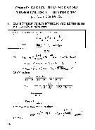
Symbols .................................................................. 8
CT ratio with current ............................................. 34
Warning and Caution Notices .................................. 8
CT / VT Voltage withstand measurements ............... 34
Open ground detection ........................................... 8
6 Standard transformer apps
Instrument safety ..................................................... 8
........................................................... 36
2.2 Safety instructions ........................................9
6.1 Winding resistance ....................................36
Maintenance ......................................................... 10
Controls for tap changer operation ........................ 36
3 Instrument description and Transformer configuration
Accessories ........................................ 12
(Vector diagram) .................................................... 37
3.1 Side panel ..................................................12
Step-by-step instructions ........................................ 39
3.2 Top panel ...................................................13
6.2 Demagnetization .......................................40
Screen and control knob ........................................ 13
Step-by-step instructions ........................................ 41
Communication and safety .................................... 14
6.3 Turn ratio ...................................................41
How to set TRAX and any accessory in safe mode .. 14
Transformer configuration...................................... 41
3.3 Included accessories ...................................16
Settings ................................................................. 42
Step-by-step instructions ........................................ 43
3.4 Optional accessories ...................................17
6.4 Excitation current ......................................44
3.5 Optional software ......................................19
Step-by-step instructions ........................................ 45 4 Basic operating
6.5 TDX TanDelta/Power Factor ........................46
........................................................... 20
Settings ................................................................. 46
4.1 General ......................................................20
Step-by-step instructions ........................................ 46
Manual and configured tests ................................. 20
6.6 Short-circuit impedance / Leakage
Test object information (nameplate) ....................... 20
reactance ................................................47
Create a test session in advance ............................. 20
Transformer configuration...................................... 48
Use measurement as template ............................... 21
Step-by-step instructions ........................................ 49 5 General operating
7 Advanced transformer apps
........................................................... 22
(optional software) ........................... 50
5.1 Main menu ................................................22
7.1 Frequency response measurement of stray
Turn off TRAX ........................................................ 22
losses - FRSL ............................................50
5.2 Apps menu ................................................23
Settings ................................................................. 50
Short app descriptions ........................................... 23
Test Parameters ...................................................... 50
5.3 Global settings ...........................................24
Transformer configuration...................................... 50
GUI Settings .......................................................... 24
Step-by-step instructions ........................................ 51 4 TRAX ZP-AJ01E AJ0383FE
Interpretation of the results ................................... 51
10 Data handling and reporting ........... 74
7.2 Magnetic balance ......................................52
10.1 General ....................................................74
Settings ................................................................. 52
10.2 Test object configuration ..........................74
Step-by-step instructions ....................................... 52
No configuration – Manual test ............................. 74
Magnetic balance with transformer configuration .. 52
Test configuration .................................................. 74
7.3 On load tap changer - OLTC .......................53
10.3 Save and report .......................................75
Settings ................................................................. 53
Action buttons ....................................................... 75 Transformer configuration
Save a test in a report file ...................................... 75
(Vector diagram) .................................................... 54
Controls for tap changer operation ....................... 54
10.4 Load file ...................................................76
Tap Operation Control ........................................... 54
Delete files ............................................................. 77
Auto Tap Switch .................................................... 54
10.5 Load template ..........................................77
Motor Current ....................................................... 54
10.6 TRAX logfile .............................................78
Result table ............................................................ 55
11 Remote control and communication
7.4 Exitation current (GOST) .............................57
ports ................................................... 80
Settings ................................................................. 57
11.1 Communication ports ..............................80
Step-by-step instructions ........................................ 57
11.2 Remote control ........................................80
8 Instrument transformer apps (optional
Connecting a device to TRAX ................................. 80
software) ........................................... 58
Off-line (simulation) mode ..................................... 81
8.1 Current transformer winding resistance......58 12 Update TRAX
Settings ................................................................. 58
........................................................... 82
Step-by-step instructions ........................................ 58
12.1 Upgrading ...............................................82
8.2 Current transformer saturation & Demag ...59
Upgrading via Internet ........................................... 82
Settings ................................................................. 59
Upgrading via USB ................................................. 82
Step-by-step instructions ........................................ 59
Getting a TRAX (USB) upgrade via PC .................... 82
8.3 Current transformer ratio U .......................60 13 Specifications
Settings ................................................................. 60
........................................................... 84
Step-by-step instructions ........................................ 60
8.4 Current transformer ratio I .........................62
Specifications TRAX .........................................84
Settings ................................................................. 62
Index ....................................................... 86
Step-by-step instructions ........................................ 62
8.5 Voltage transformer ratio ...........................63
Settings ................................................................. 63
Step-by-step instructions ........................................ 64 9 Substation apps
(optional software) ........................... 66
9.1 Contact resistance ....................................66
Settings ................................................................. 66
Connection for measurement ................................ 67
9.2 Circuit breaker ...........................................68
Settings ................................................................. 68
Step by step instruction ......................................... 68
Test result parameters ............................................ 70
9.3 Line impedance (k-factor) ...........................72 AJ0383FE ZP-AJ01E TRAX 5 1 INTRODUCTION 1 Introduction 1.1 Product description
1.2 Features and benefits
TRAX™ is a unique testing instrument designed to
▪ Multi-function system for transformer/substation
accomplish routine and advances diagnostics on testing
power, distribution and instrument transformers as
▪ Flexible AC / DC current and voltage sources for a
well as on many other substation components. variety of tests.
A wide range of AC DC current and voltage sources
▪ State of the art measurement methods for advanced
together with high precision metering instrumen- diagnostic testing
tation allow TRAX to be used in a wide range of
▪ Variable output frequency for accurate
applications such as resistance, ratio, excitation,
measurements in high interference environments
impedance and primary measurements of power system components. ▪ Compact and lightweight
TRAX is a unique test system for testing power User interface
transformers, CTs, VTs, and a variety of other power
components. TRAX is capable of providing up to
TRAX user interface architecture is based on a
800 A and 2200 V (up to 2000 A and 12000 V with
number of individual test set-ups/”instruments”, in
optional accessories) with a frequency range of
this manual called “Apps”, where only the necessary
5-505 Hz (1-505 for insulation testing) and can be
functionality is displayed by default. All Apps are
controlled via integrated touch-screen or an external
“ready to go” in manual test mode without doing any
computer device with a web browser. The compact
specific settings. Just select the amplitude of the test
design weighs in at only 26 kg (TRAX220) and can be
signal and press start/play. If you prefer guidance from
shipped in its transportation case within the limits of
TRAX on how to perform the measurement, enter check-in luggage (< 32 kg).
the configuration and TRAX will provide connection
diagrams and a table with the order of measurements.
And if a specific non-standardized measurement is
needed, the “Manual control” instrument can be
used to generate any voltage or current test signal
and measure the necessary parameters.
All results can be stored and reported as a specific
report containing test object information and all tests
or as data to be imported in e.g. Excel. When testing
a certain substation component, e.g. a power trans-
former, all measurements from different Apps can be
collected in one report/file. It is also possible to use
a former measurement as a template for a new test session. 6 TRAX ZP-AJ01E AJ0383FE 1 INTRODUCTION Applications 1.3 Warranty
A wide range of voltage and current levels can be
Products supplied by Megger are warranted against
achieved and measured with high precision which
defects in material and workmanship for a period of
allows the test system to be used for a wide range of one year following shipment.
applications such as ratio, excitation current, winding
and contact resistance, impedance, tan delta/power
Our liability is specifically limited to replacing or
factor testing and various other measurements of
repairing, at our option, defective equipment. power system components.
This warranty does not include batteries, lamps or ▪ Examples are:
other expendable items, where the original manufac-
turer’s warranty shall apply. ▪ Power transformer
We make no other warranty. The warranty is void ▪ Current transformer
in the event of negligence and / or abuse (failure to ▪ Voltage transformer
follow recommended operating procedures) or failure ▪ Resistance testing
by the customer to perform specific maintenance as indicated in this manual. ▪ Primary injection testing Receiving Instructions
▪ Check the equipment received against the packing
list to ensure that all materials are present. Notify Megger of any shortage.
▪ Examine the instrument for damage occurred in
transit. If damage is identified, file a claim with the
carrier at once and notify Megger giving a detailed description of the damage.
▪ The instrument has been thoroughly tested,
calibrated and inspected to meet rigid specifications
before being shipped. It is ready for use when set
up as indicated in this user manual. Warranty repair
Equipment returned to the factory for repair must be shipped prepaid and insured.
Contact your Megger representative for instructions
and a return authorization (RA) number.
Please indicate all pertinent information, including problem symptoms.
Also specify the serial number and the catalog number of the unit. AJ0383FE ZP-AJ01E TRAX 7 2 SAFETy 2 Safety 2.1 General Warning Important
Warning, as used in this manual, is defined as
Read and comply with the following in-
a condition or practice which could result in structions.
personal injury or loss of life.
Always comply with local safety regula- tions. Caution
Caution, as used in this manual, is defined as Symbols
a condition or practice which could result in
damage to or destruction of the equipment or
Caution, refer to accompanying docu- apparatus under test. ments. Open ground detection
Protective conductor terminal/test ground.
1. The unit has an open ground detection circuit
which gives alarm if the mains outlet ground
is missing or different from the station/test Ground
specimen ground. The alarm can be configured For connecting an additional
by the user to give an alarm only or actually lock
ground between the main unit and
the unit and prohibit any test signal generation.
accessories or to ground external objects e.g. optional trolley.
2. The mains outlet must have a PE, protective Open ground = the ground Loop
earth (ground) connected to station ground.
Detector will indicate that the separate
Normally mains outlet PE is connected to station
“Test Ground” on the side panel is not
ground. If that is not the case there are two
connected to safety/chassis ground. alternatives:
▪ In compliance with local safety regulations
WEEE, Waste Electrical and Electronic
and permits, use an isolation transformer
Equipment. Please utilize your local
where the secondary side Earth/Ground is
WEEE collection facilities in the dispo-
to be connected to station ground using a
sition of this product and otherwise
observe all applicable requirements.
separate ground cable (not via TRAX unit!)
The unit can be returned to Megger at
▪ In compliance with local safety regulations
any time at no charge for the disposal.
and permits, use a temporary grounding
connection by connecting mains outlet
Information duty regarding substances ground with station ground.
on REACH article 33, SVHC-list
This product contains a coin cell battery which Instrument safety
contains 1,2- dimethoxyethane (CAS 110-71-4) above 0.1% by weight.
1. This instrument operates from a single-phase
power source. It has two-pole terminal with
ground connector and requires a two-pole, 16A,
Warning and Caution Notices
three-terminal, voltage and ground type con-
Warning and caution notices are used throughout
nector. The voltage of the power source must
this manual where applicable and should be strictly
be within the following rated operating voltage:
observed. These notices appear in the format shown 100-240 V ± 10 %, 47 / 63 Hz.
below and are defined as follows: 8 TRAX ZP-AJ01E AJ0383FE 2 SAFETy
2. Before making connection to the power source, 2.2 Safety instructions
determine that the instrument rating matches
the voltage of the power source and has a suita-
1. It is not possible to eliminate all potential
ble two-pole terminal with ground connector.
hazards from, and in using, electrical test
3. The power input plug must be inserted only
equipment. For this reason, every effort has
into a mating receptacle with a ground contact.
been made to point out in this instruction
Do not bypass the grounding connection. Any
manual the proper procedures and precautions
interruption of the grounding connection can
to be followed by the user in operating this
create an electric shock hazard. Determine that
equipment and to mark the equipment itself
the receptacle is properly wired before inserting
with precautionary warnings where appropriate. the plug.
It is not possible to foresee every hazard which
may occur in the various applications of this
equipment. It is therefore essential that the user,
in addition to following the safety rules in this
manual, also carefully consider all safety aspects of the test before proceeding.
2. The test set and the specimen to which it is
connected are a possible source of high-voltage
electrical energy and all persons making or
assisting in tests must use all safety practice
precautions to prevent contact with energized
parts of the test equipment and related circuits.
3. Persons actually engaged in the test must stand
clear of all parts of the complete high-voltage
circuit, including all connections, unless the
test set is de-energized and all parts of the
test circuit are grounded. Persons not directly
involved with the work must be kept away from
test activities by suitable barriers, barricades, or warnings.
4. Treat all terminals of high-voltage power
equipment as a potential electric shock hazard.
There is always the potential of voltages being
induced at these terminals because of proximity
to energized high-voltage lines or equipment.
5. Always ground connection points of the test
specimen before connecting any leads from the
test set. Whenever possible, always keep one
side of the test specimen grounded at all times.
Always use a safety ground stick to ground any high-voltage conductor.
6. The ground connection on the test set must
be the first made and the last removed. Any
interruption of the grounding connection can
create an electric shock hazard.
7. Make sure that the instrument is properly
grounded, both through its AC power cord and
through the ground connector. The AC power
cord is the disconnecting device.
8. Always disconnect test leads from test specimen
before attempting to disconnect them at the test set. AJ0383FE ZP-AJ01E TRAX 9 2 SAFETy
9. High-voltage discharges and other sources of
3. Read and understand Safety in the User Manual
strong electric or magnetic fields may interfere before performing any service.
with the proper functioning of heart pacemak-
4. Routine maintenance is all that is required for
ers. Persons with heart pacemakers should
these test sets. The cables and connector panel
obtain expert advice on the possible risks before
should be inspected frequently to be sure all
operating this equipment or being close to the
connections are tight and all ground connec- equipment during operation. tions intact.
10. All persons making or assisting in tests must
5. The appearance of the test set can be main-
use all practical safety precautions to prevent
tained by occasional cleaning of the case,
contact with energized parts of the test equip-
panel and cable assemblies. The outside of the
ment and related circuits. Also follow all local
carrying case can be cleaned with detergent and
and company safety requirements. Persons
water. Dry with a clean, dry cloth. The control
actually engaged in the test must stand clear of
panel can be cleaned with a cloth dampened
all parts of the complete high- voltage circuit,
with detergent and water. Do not allow water
including all connections, unless the test set is
to penetrate panel holes, because damage to
de-energized and all parts of the test circuit are
components on the underside may occur. A
grounded. Persons not directly involved with the
household all-purpose spray cleaner can be used
work must be kept away from test activities by
to clean the panel. Polish with a soft, dry cloth,
suitable barriers, barricades, or warnings.
taking care not to scratch the display screen
11. Safety is the responsibility of the user.
cover. The cables and mating panel receptacles
12. Misuse of this high-voltage equipment can be
can be cleaned with isopropyl or denatured extremely dangerous.
alcohol applied with a clean cloth.
13. The purpose of this equipment is limited to use
as described in this manual. Do not use the
equipment or its accessories with any device
other than specifically described.
14. Before making any connections, make sure that
the instrument is de-energized and that all parts
of the test circuit are properly grounded.
15. Never connect more than one output at the
time. All outputs are energized by the same
amplifier and therefore all outputs are energized simultaneously.
16. Operation is prohibited in rain or snow.
17. Do not use the test set in an explosive atmosphere.
18. A qualified operator should be in attendance
at all times while the test equipment is in operation.
19. Observe all safety warnings marked on the equipment.
20. Corrective maintenance must only be performed
by qualified personnel who are familiar with the
design and operation of the test set and the hazards involved. Maintenance
1. DISCONNECT the MAINS plug before any cleaning or maintenance.
2. Maintenance should be performed only by
qualified personnel familiar with the hazards
involved with high-voltage test equipment. 10 TRAX ZP-AJ01E AJ0383FE 2 SAFETy AJ0383FE ZP-AJ01E TRAX 11
3 INSTRUMENT DESCRIPTION AND ACCESSORIES
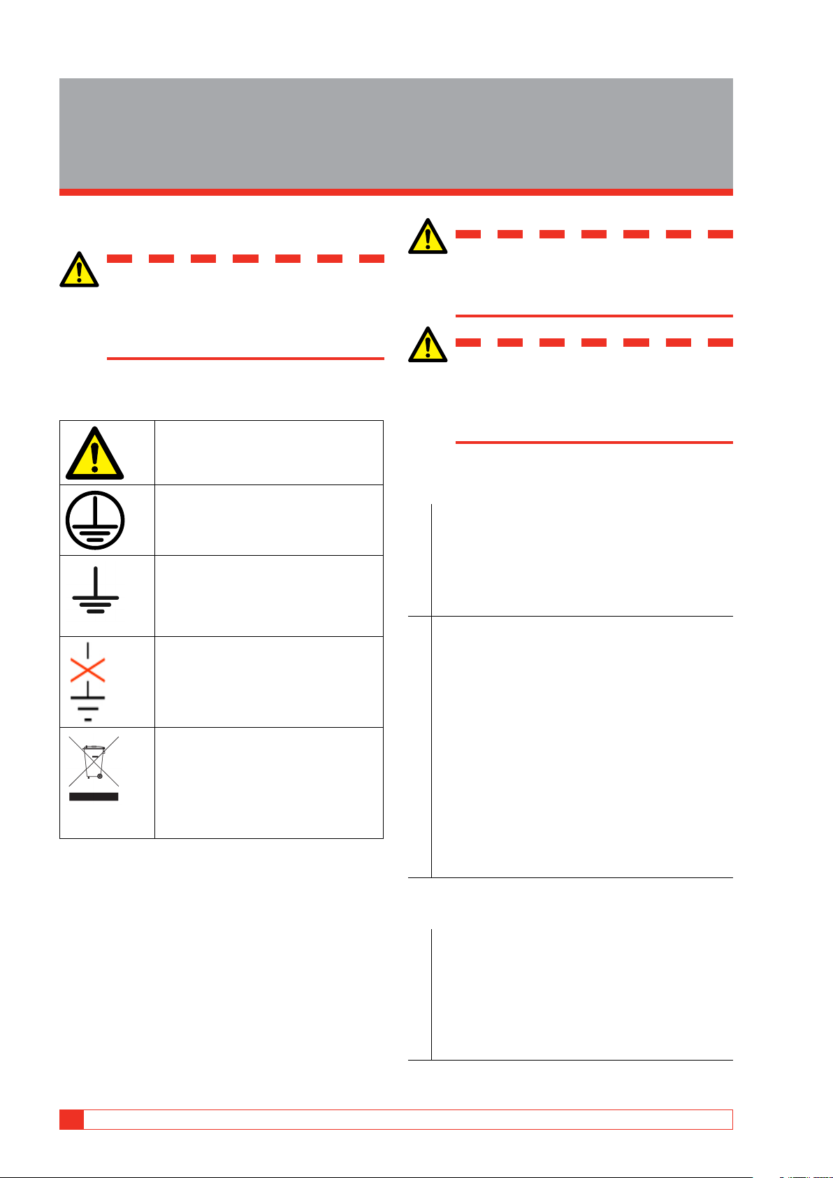
3 Instrument description and Accessories 3.1 Side panel 7 1 8 2 3 4 9 5 10 11 12 6 13 1. 0-2200 V AC 11. Mains >265 V AC
1 A (max 1 minute). The output is additionally
LED is lit if mains voltage exceeds 265 V. An elec-
disconnected with a relay and the output is “live”
tronic protection switches off the generation.
only when this generator is selected.
12. MAINS INPUT 100-240 V AC, 16 A, 50/60 Hz 2. 0-250 V AC / 0-10 A Single phase + Ground. 10 A (max 1 min) 3. 0-16 A DC 13. Ground 0-1 or 0-16 A continuous
For connecting an additional ground between 4. 0-300 V DC
the main unit and accessories or to ground exter-
Rectified AC, max 10 A for 1 minute
nal objects e.g. optional trolley. 5. 0-100 A DC
100 A (max 2 minutes, continuous 70 A) WARNING
6. 0-200 A AC / 0-800 A AC
TRAX 220: 0-200 A (6 V), TRAX 280: 0-800 A (6 V)
The outputs 1, 2, 4 and 6 are connected 7. AUX CONTROL
internally to the same output transformer
Ethernet communication and power (48 V DC) to
and should be considered “live” when accessories.
one of the outputs is activated. 8. F1 F2
Never connect more than one output at a Main fuses 25 A time. 9. AUX POWER
Output 0-235 V AC directly from power amplifier
Test objects should be grounded at one
for powering accessories, TRAX TDX and TRAX
end to minimize risk for high voltage in- TCX.
terference entering the instrument. 10.
Protective conductor terminal
To be connected to the test object ground before
connecting any other cables to the unit. 12 TRAX ZP-AJ01E AJ0383FE
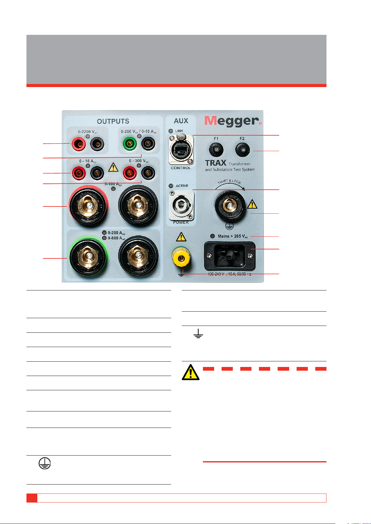
3 INSTRUMENT DESCRIPTION AND ACCESSORIES 3.2 Top panel 1 2 Screen and control knob
1. Capacitive touch screen, TRAX 220 and 280.
2. Control knob for controlling selected output
generator. Press to change value for the incre-
mental steps (e.g. 1 V, 2 V, 5 V, 10 V).
Used as pairing device when connecting TRAX
for external control via Ethernet or Wifi.
Cursor up/down when reading reports. AJ0383FE ZP-AJ01E TRAX 13
3 INSTRUMENT DESCRIPTION AND ACCESSORIES
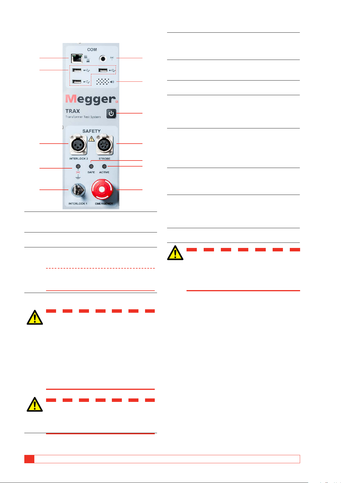
Communication and safety 5. INTERLOCK 1
Fixed interlock with key switch. If the key is in
the OFF position, or is not in the unit, the power 1 6 amplifier is OFF.
6. Connector for Wifi antenna, making it possible 2
to run the instrument wireless from a PC or tab- let (option). 7
7. Communication Speaker
Beeper under the panel for sound indicator. 8. ON / OFF
Press button for 1 second and the instrument will 8 start.
Press for 3 seconds and the instrument will shut off. 9. STROBE
For connection of the optional TIB225, Trax 3 9
Indicator Box, Indicating safe (green) or voltage/ current generating (red). 10
The optional TIB225 acts similar to the indicator
lights on the panel (10 and 11). 4 11 10. SAFE
Green LED indicates that the instrument is in a
safe state for connecting and disconnecting of 5 12 cables. 11. ACTIVE Indicator
Red LED flashes – Instrument is generating a
voltage or current or discharging an inductive
1. Ethernet port for running the instrument from
circuit after a DC test (winding resistance meas-
an external PC or connect it to an external net- urements). work. 12. EMERGENCY
2. Three USB ports for multipurpose use: USB mem-
Emergency shut down (ESD) button.
ory stick, external mouse or keyboard. 3. INTERLOCK 2
Manual interlock. If activated, the power amplifi- Warning
er shuts off when the interlock is open.
If any of the two indicators above, 10 and
Note Interlock 2 can not be deactivated for 2.2 kV
11, does not work properly, the TRAX and
output and when using the TDX120 acces-
any TRAX accessory, must be considered sory.
in generating (unsafe) mode.
4. The orange LED will indicate if the TRAX is not properly grounded.
How to set TRAX and any WARNING accessory in safe mode
When the LED is flashing, one or more
There are two ways to set TRAX in a safe mode, which
of the following criteria is not met:
means that it can not generate any voltage / current.
Test ground is not connected to ground
Test ground cable is connected poorly
▪ Put INTERLOCK 1 key into vertical position (locked). Test ground cable is faulty
During normal operation when the TRAX shall be set
The mains outlet is not grounded in a safe mode.
The mains cable ground is faulty
Station ground and test object ground
▪ Press the EMERGENCY button. are not on the same potential
In emergencies when all generation from TRAX and its
accessories shall be stopped immediately. Important Safety is always a priority.
Make sure that the TRAX system is prop- erly grounded.. 14 TRAX ZP-AJ01E AJ0383FE
3 INSTRUMENT DESCRIPTION AND ACCESSORIES
Transducer, binary outputs and Analog inputs timing 1 2 3 1 2 3 4 1. TRANS 5
General input for analog transducers and low
level analog signals e.g. motion transducers, Rogowski coils etc. 2. CONTROL
close/open contacts for OLTC and circuit-breaker 4 control (up-down, close-trip) 3. TRIG IN
External trig input for starting measurements or
recording based on external event. 1. VOLTAGE INPUTS 4. TIMING
Four channels 0-250 V AC, 0-350 V DC
Binary inputs for timing measurements in timer 2. CURRENT INPUTS
and relay testing applications when used as a
Four channels 0-10 A AC, 0-10 A DC
timer. A and B inputs dedicated for Start and Stop.
Note Voltage and current cannot be measured on
the same channel simultaneously. 3. FUSES
4 x 500 mA/25 V AC fast, can be changed from
the outside, protects the low current gain shunt.
Inside the top panel, there are 4 x 15 A/250 V AC
fast fuses for the high current gain step 4. DC INPUTS
These two channels (R1 & R2) are designed for
measuring low DC voltage, < 60 V DC, when
measuring contact and winding resistance, using
the 100 A or 1 to 16 A DC current outputs. If the
channels are used for measuring AC, max input is 40 V RMS. 5. LED INDICATORS
Red LED’s indicate which channel to connect to depending on what App is used. AJ0383FE ZP-AJ01E TRAX 15
3 INSTRUMENT DESCRIPTION AND ACCESSORIES
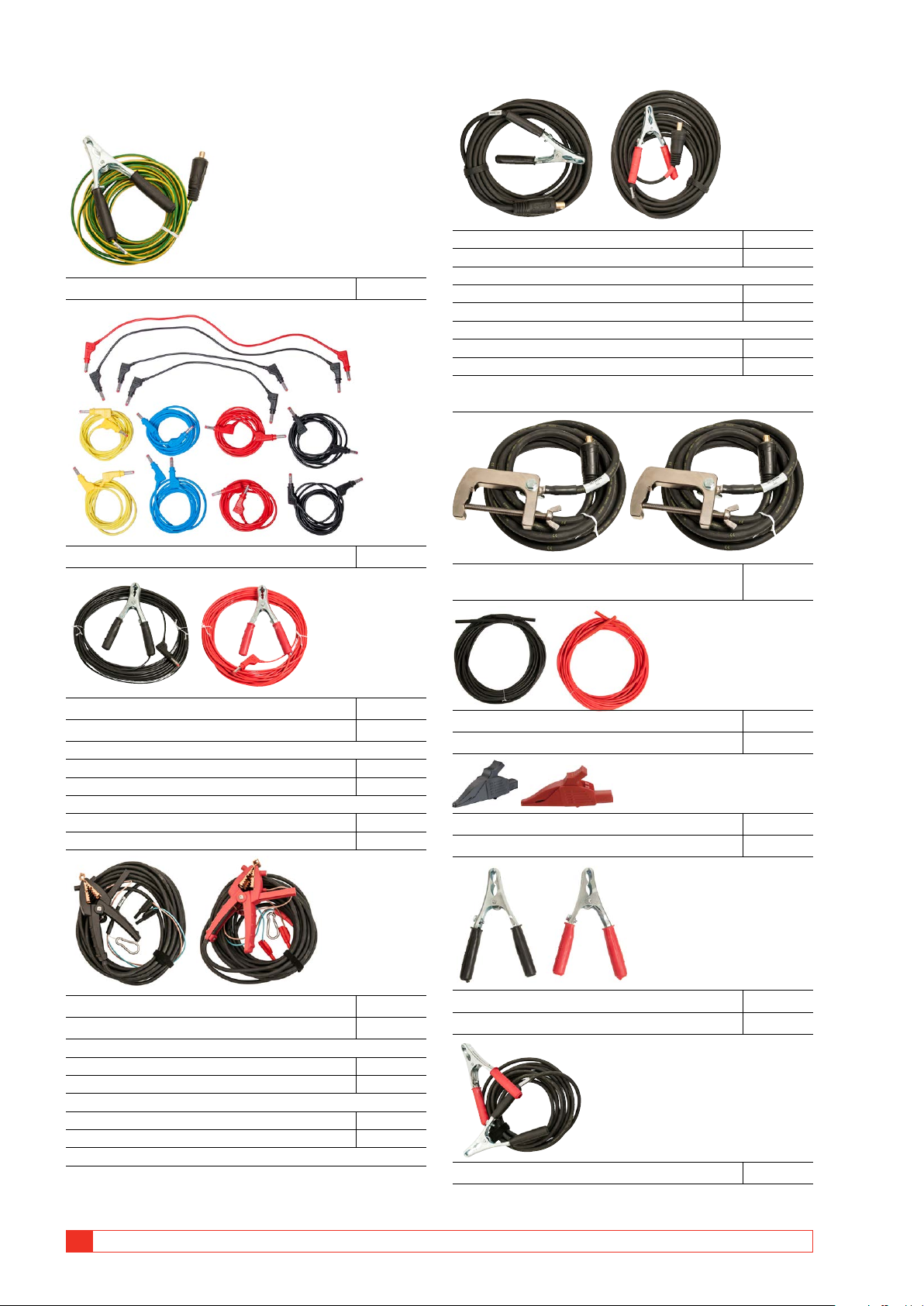
3.3 Included accessories
Current cable, 35 mm2, 10 m (33 ft), black GC-32010
Current cable, 35 mm2, 10 m (33 ft), red GC-32012 OR
Ground cable, 6 mm2, 10 m (33 ft) GC-30080
Current cable, 35 mm2, 15 m (49 ft), black GC-32015
Current cable, 35 mm2, 15 m (49 ft), red GC-32017 OR
Current cable, 35 mm2, 20 m (66 ft), black GC-32020
Current cable, 35 mm2, 20 m (66 ft), red GC-32022
Note: For TRAX 219/220 with 15/20 m cables are also a pair of
current cables, 35 mm2, 6 m (20 ft) included. Test cable set GA-00032
Current cable, 800 A, 95 mm2, 2 x 6 m (20 ft), GC-32106 (TRAX 279/280)
Sense cable, 10 m (33 ft), black KG-00530 HV cable, 10 m (33 ft), black 04-35310 Sense cable, 10 m (33 ft), red KG-00532 HV cable, 10 m (33 ft), red 04-35315 OR
Sense cable, 15 m (49 ft), black KG-00540 Sense cable, 15 m (49 ft), red KG-00542 OR
Sense cable, 20 m (66 ft), black KG-00570 Al igator clip, black 40-08320 Sense cable, 20 m (66 ft), red KG-00572 Alligator clip, red 40-08322
Kelvin cable, 10 m (33 ft), black GC-32310
Large clamp for HV-cable, black GC-80040
Kelvin cable, 10 m (33 ft), red GC-32312 Large clamp for HV-cable, red GC-80042 OR
Kelvin cable, 15 m (49 ft), black GC-32315
Kelvin cable, 15 m (49 ft), red GC-32317 OR
Kelvin cable, 20 m (66 ft), black GC-32320
Kelvin cable, 20 m (66 ft), red GC-32322
Note: Only included in the Power transformer testing
Jumper cable, 10 mm2, 5 m (16 ft) GC-32091 16 TRAX ZP-AJ01E AJ0383FE
3 INSTRUMENT DESCRIPTION AND ACCESSORIES
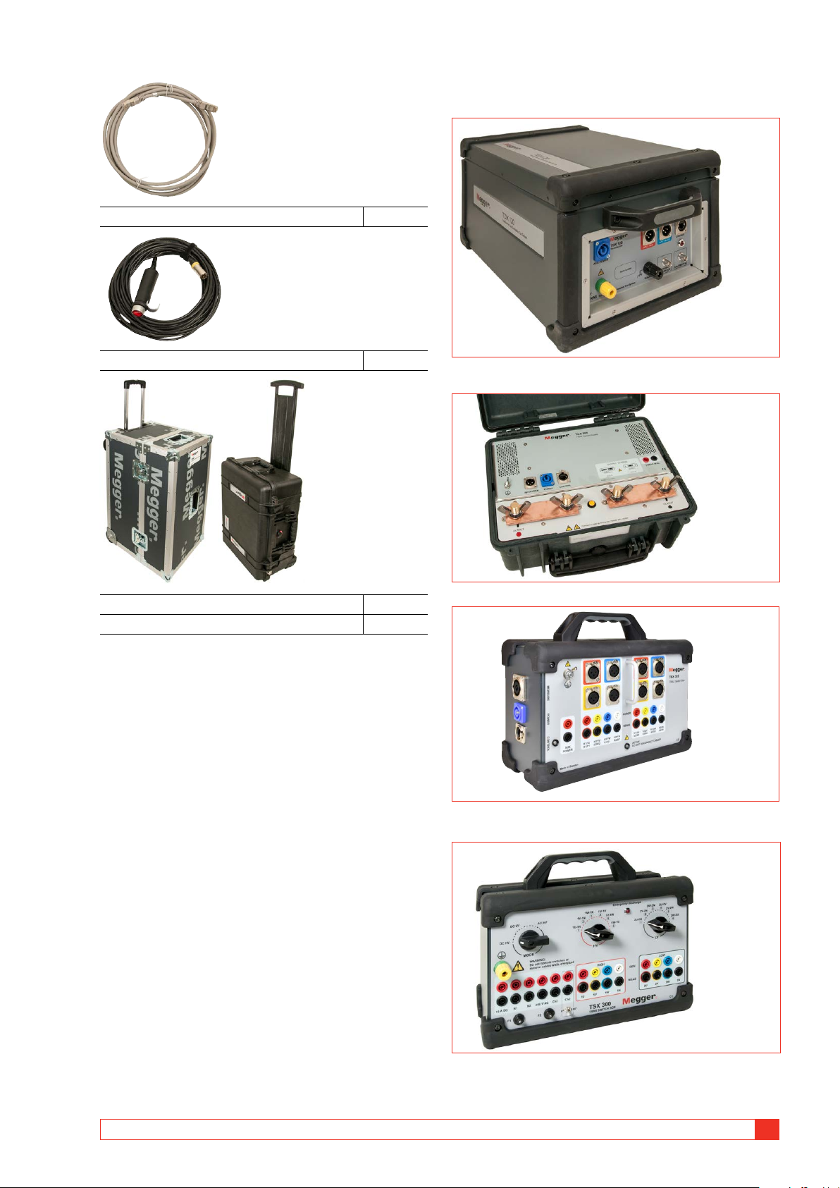
3.4 Optional accessories Ethernet cable, shielded GA-00985 TDX 120, AJ-69090
Saftey hand switch interlock, 3 m (10 ft) GC-31103
High voltage unit (12 kV) for excitation current and,
capacitance and DF/PF/Tan-delta measurements. TCX 200, AJ-69290 High current accessory. Transport case, with wheels GD-30200
Case for accessories, with wheels GD-30220 TSX 303, AJ-69490
3-phase/6-winding automated switchbox.
Note: Release is planned during 2018 TSX 300, AJ-69390 / AJ-69395
3-phase/6-winding manual switchbox with IEC or ANSI panel design. AJ0383FE ZP-AJ01E TRAX 17
3 INSTRUMENT DESCRIPTION AND ACCESSORIES
Interlock hand switch, GC-31120
Saftey hand switch interlock, 18 m (60 ft) Line impedance kit, AJ-69690
The Line Impedance Kit is an accessory for TRAX. It consists of
TSA230 - surge arrester unit and TPB230 - protection box, plus
cables, accessories and AJ-8050X software app for TRAX. Soft light case, GD-31050
Soft case for TRAX, except accessories, to minimize weight for flight purpose. B10E, BG-29092
A variable DC voltage can be needed to test a circuit breaker.
The B10E supplies 24-250 V AC or DC. TIB225, AJ-90030
TIB225, Trax Indicator Box, Indicating safe (green) or voltage/ current generating (red) Trolley, AJ-90040
Trolley suited for TRAX and optional accessories, e.g. TDX 120
Interlock foot switch, GC-31150
Saftey foot switch interlock, 3 m (10 ft) Connection kit, GA-90010
Connection kit for Control cables 18 TRAX ZP-AJ01E AJ0383FE
3 INSTRUMENT DESCRIPTION AND ACCESSORIES 3.5 Optional software Advanced transformer AJ-8020X ▪
▪ Dynamic OLTC measurements (DRM) ▪
▪ FRSL (frequency response of stray losses) ▪ ▪ Magnetic balance Instrument transformer AJ-8030X ▪ ▪ CT ratio ▪ ▪ CT burden ▪
▪ CT excitation curve (knee point) ▪ ▪ CT polarity ▪ ▪ CT winding resistance ▪ ▪ VT ratio ▪ ▪ VT burden ▪ ▪ VT polarity Substation AJ-8040X ▪ ▪ Circuit-breaker analyzer ▪ ▪ Relay over current timing ▪ ▪ Timer ▪ ▪ Phase angle meter (manual) ▪
▪ Ground/earth/impedance (manual) Line impedance/K-factor AJ-8050X
Note: Hardware needed (TSA230 - surge arrest-
er unit and TPB230 - protection box, cables and accessories).
Recommended cables for SW AJ-8040X Test lead set: GC-32600
4 Test lead, 0.5 m (1.6 ft) red/black/yel ow/blue
6 Test lead, 2 m (6.5 ft) red/black/yel ow/blue
4 Test lead, 5 m (16 ft) red/black/yel ow/blue 4 Dolphin clamp (black/red) Timing test lead set: GC-32610 6 Clamp with banana jack
6 Test cable, 10 m (33 ft) black/red
Connection kit for Control cables: GA-90010 5 Test clip 5 Adapter for terminal block 5 Cable lug adapter 1 Plastic box AJ0383FE ZP-AJ01E TRAX 19 4 BASIC OPERATING 4 Basic operating 4.1 General
how many taps. Using this information the TRAX app
is mastering the test and you have to perform the test
TRAX measurements are collected together in test
following the connections described by the unit to get
sessions and tests. A test is often containing sev-
the automatic assessment of the test.
eral individual measurements and a TRAX test ses-
Also in a configured test, you may use several test to
sion / file / report often contains several tests performed
fully test a transformer. As an example, if the test ob- with different apps .
ject is a three-winding transformer, TTR measurements
need to be performed is several test, e.g. Primary
Manual and configured tests
windings to Seconday windings, Primary to Tertiary
and Secondary to Tertiary. Each of these is done as Manual control
a separate test with a separate test table, collected
Manual tests can be done by using Manual control
together in the same test session.
where you define what generator to use, type of test
signal, how results are measured and how parameters
Test object information
are calculated. This gives unlimited possibilities to (nameplate)
perform almost any AC or DC test on any electrical
component within the limits of TRAX generating
Test object / nameplate information must be entered capabilities.
for any configured test and will be part of the test
report. The mandatory information needed for a
Results from Manual control measurements for a
certain app is asked for and added to the report. The
certain setup are collected in a result table. If the test
next app will have the same information automatically
setup is modified due to change of measurement
but may need some additional information to be
channels and/or calculated parameters, the new
added. After all tests you can go to the report and
results are collected in a new test/results table.
add any information that is still missing. Manual test
Create a test session in advance
It is also possible to use TRAX as a manual standard
instrument. This operation mode is defined as
If a test session needs to be defined before the test is
“Manual Test / No configuration” and “is available in
actually performed, the workflow is the following:
most of the Apps. Compared to Manual control, this
1] Open the first app and define the test object,
operation mode is locked to a certain application.
define parameters such as: transformer vec-
As an example, winding resistance measurements in tor group.
Manual Test mode is limited to using any of the three
DC current generators and one or two DC measure-
2] Name and save (the empty) test. ment inputs.
3] Go to the report and fill in all necessary in-
Results from Manual Test measurements for a certain
formation for the test object and all planned
setup are collected in a results table. If the test setup tests.
is changed by e.g. changing from single to dual
4] Open the next app to create a test table
channels (simultaneous winding magnetization)
5] Save and go to the next app. Continue as
winding resistance, the new results are collected in a above for all desired apps. new test / result table.
6] Finally check the report once again to see Configured test
that all the needed data is entered and that
Configured tests are defined by entering information all planned tests are there.
about the test object, as is the case of vector group
7] Confirm/save and close.
and configuration of a power transformer, if there is
a tap-changer or not and if so on what winding and 20 TRAX ZP-AJ01E AJ0383FE