RF Signals and Systems | Bài giảng Nhập môn kỹ thuật truyền thông| Trường Đại học Bách Khoa Hà Nội
RF Signals and Systems | Bài giảng Nhập môn kỹ thuật truyền thông| Trường Đại học Bách Khoa Hà Nội. Tài liệu gồm 13 trang giúp bạn ôn tập và đạt kết quả cao trong kỳ thi sắp tới. Mời bạn đọc đón xem.
Môn: Nhập môn kỹ thuật truyền thông 14 tài liệu
Trường: Đại học Bách Khoa Hà Nội 5.7 K tài liệu
Tác giả:


Preview text:
Advanced level study programme in Elect
Advanced level study programme ronics Design an in Elect d Integration Tech ronics Design an nologies d Integration Tech
28213-IC-1-2005-1-BE-ERASMUS-PROGUC-3 2006-2322 / 001-001 SO2 RF Signals and Systems
1. Introduction. Communications Systems Ivan Uzunov RF Signals and Systems
1. Introduction. Communication Systems 1/13 1/13 Table of Contents
1. Information, Messages, Signals ............................................................................................................ 3
2. Elements of a Communication System ................................................................................................. 4
3. Fundamental Limitations in Communications ...................................................................................... 7
3.1. Limitations Due to Technological Problems ................................................................................... 7
3.2. Fundamental Physical Limitations .................................................................................................. 8
4. Modulation ............................................................................................................................................ 9 RF Signals and Systems
1. Introduction. Communication Systems 2/13
1. Information, Messages, Signals
Information: general intuitive term.
Message: a physical manifestation of the information as produced by the source.
Various sources of messages (people, machines, measuring instruments, etc.).
Analog message: a physical time-variable quantity usually in smooth and continuous form.
Digital message: ordered sequence of symbols selected from finite set of elements.
Signal: physical embodiment of the information. Signal ≈ Message
Electrical signal: voltage or current representing the message. RF Signals and Systems
1. Introduction. Communication Systems 3/13
2. Elements of a Communication System
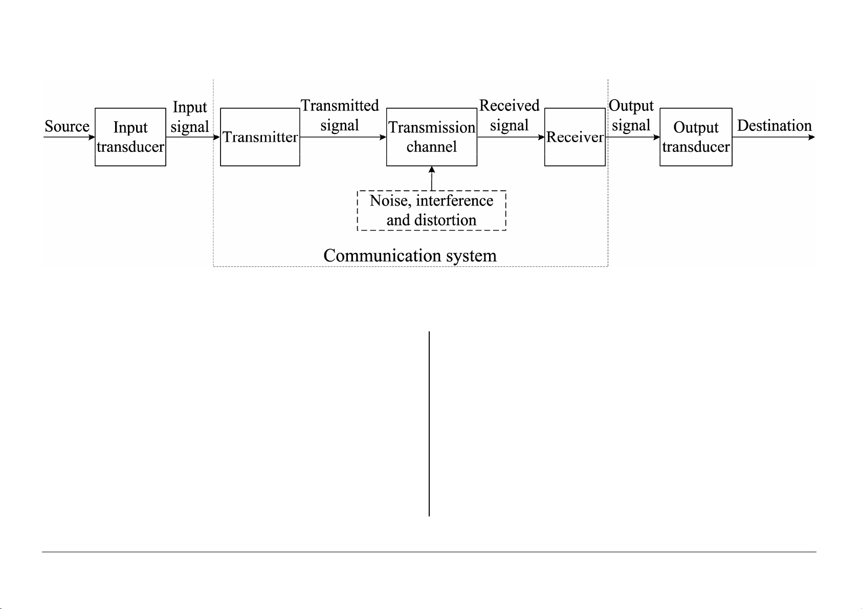
Figure 1. Block-diagram of a communication system with input and output transducers.
Input transducer converts the message to an
The receiver converts the received signal in a electrical signal.
form appropriate for the output transducer.
The transmitter converts the input signal to
Output transducer converts the output electrical
transmitted signal suited for the transmission
signal the desired message form. channel.
Transmission cannel is the electric medium that
bridges the distance from source to destination. RF Signals and Systems
1. Introduction. Communication Systems 4/13
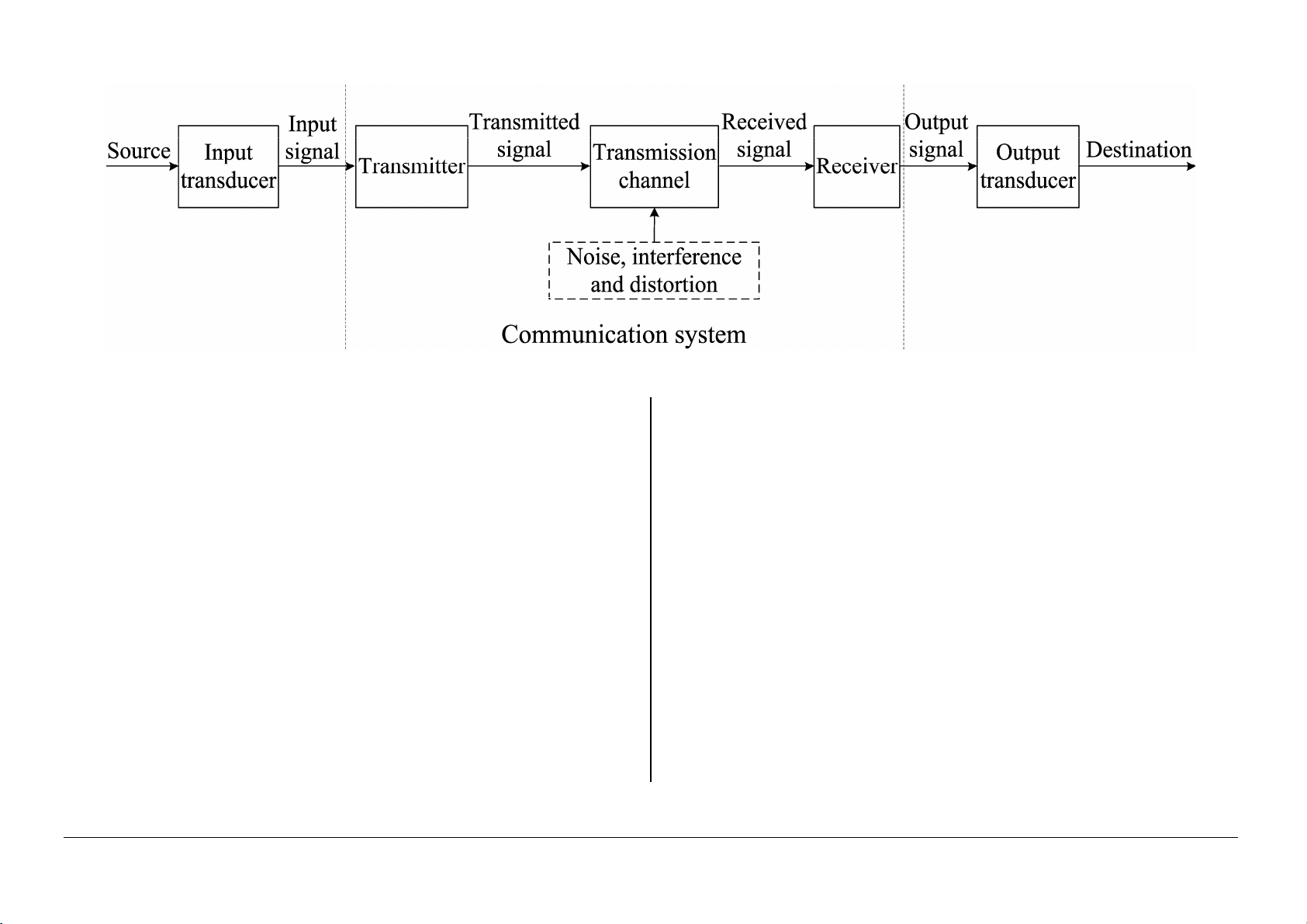
Figure 1 (repeated). Block-diagram of a communication system with input and output transducers.
Basic operations in the transmitter
Effects of the channel on the transmitted signal • Modulation
• Attenuation: decreasing the signal strength; • Coding
• Distortion of the signal waveform: caused by
channel characteristics (linearity, frequency
Basic operations in the receiver response, etc.) • Amplification
• Noise: contamination of random natural signals • Filtering
added to the transmitted signal • Demodulation
• Interference: contaminations of extraneous • Decoding
signal of human sources – machinery, power
lines, digital switching circuits, etc. RF Signals and Systems
1. Introduction. Communication Systems 5/13
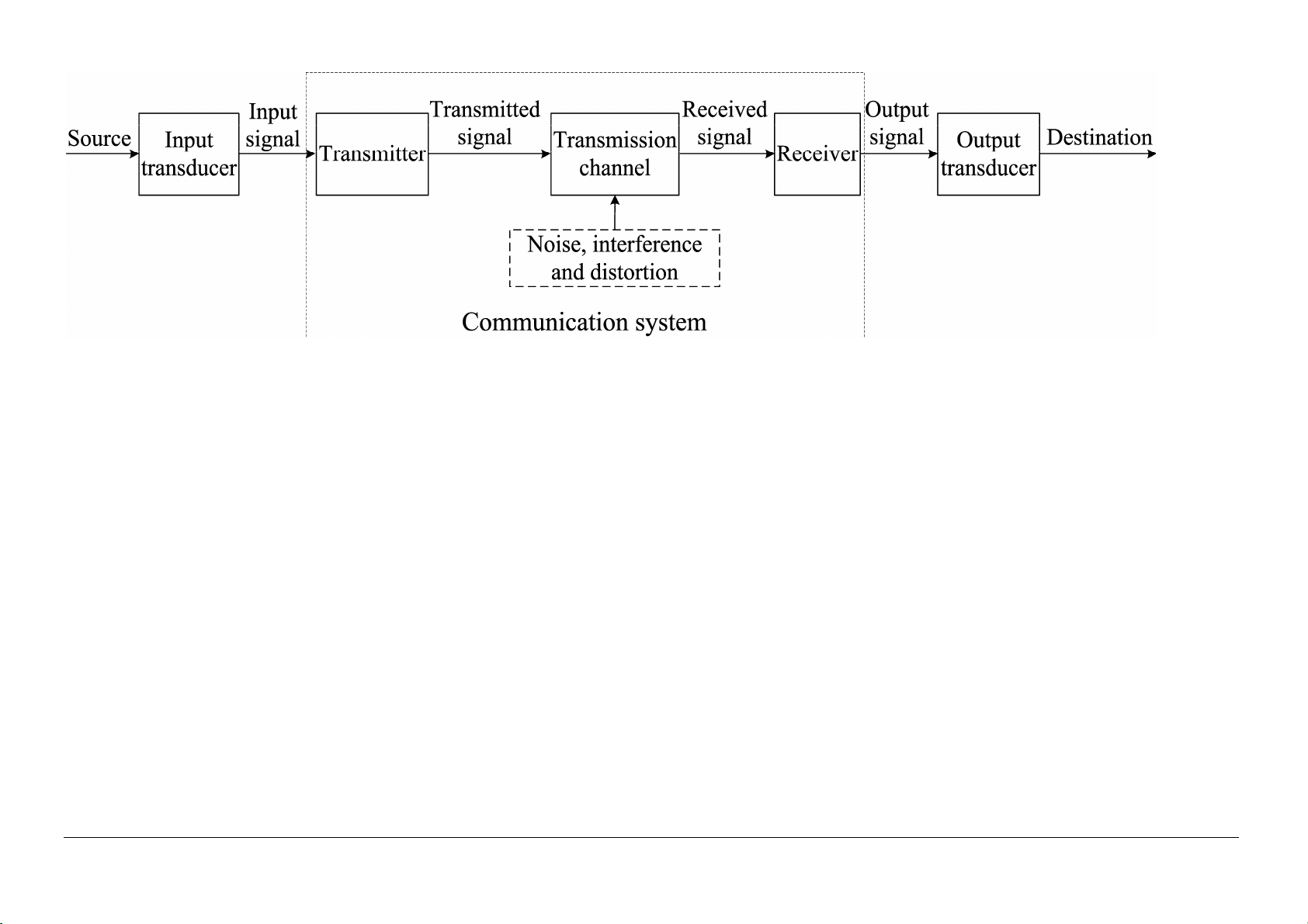
Figure 1 (repeated). Block-diagram of a communication system with input and output transducers.
One-way or simplex (SX) transmission. Transmission in one direction only. Example - Figure 1.
Full-duplex (FDX) system – a system, which channel allows transmission in both directions.
Full-duplex (HDX) system – a system, which channel allows transmission in both directions but not simultaneously. RF Signals and Systems
1. Introduction. Communication Systems 6/13
3. Fundamental Limitations in Communications
3.1. Limitations Due to Technological Problems • Hardware availability • Economic factors
• International and national regulating norms RF Signals and Systems
1. Introduction. Communication Systems 7/13
• The noise degrades the fidelity in analog
3.2. Fundamental Physical Limitations
communication systems and produces errors in
3.2.1. Transmission Bandwidth B. digital communications.
• Limits the spectrum of the transmitted signal,
• Noise generation limits the weakest transmitted
i.e. the maximum speed of variation of the
signal. Significant in long-distance transmitted signal.
communications when the signal attenuation is large.
• The time required for transmission of a given
amount of information is inversely proportional to
• Signal-to-noise ratio S/N
the transmission bandwidth B. p of ower the signal S N = of power noise the 3.2.2. Noise
• Noise is generated in all conductors and in
3.2.3. Hartley-Shannon low electronic devices as well.
The rate of information transmission cannot
• Thermal noise due to random motion of the
exceed the channel capacity C
charged particles like electrons.
C = B log(1 + S N )
• Noises generated in electronic devices: shot, flicker, popcorn, avalanche. RF Signals and Systems
1. Introduction. Communication Systems 8/13 4. Modulation
4.1. Modulation Methods
• Modulating signal – represents the message.
• Carrier wave – suits the application.
• Usually the modulation signal is much slower than the carrier wave.
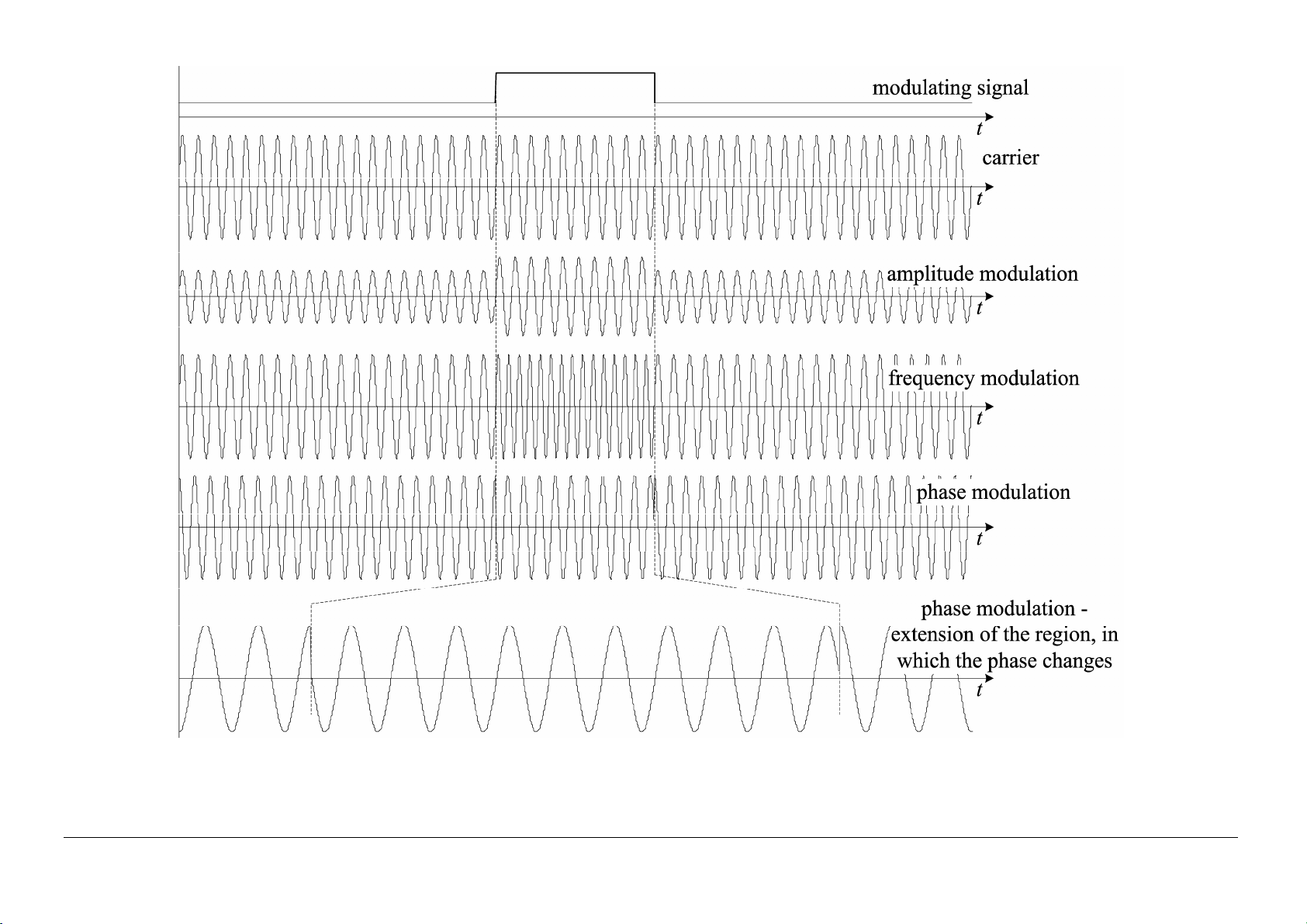
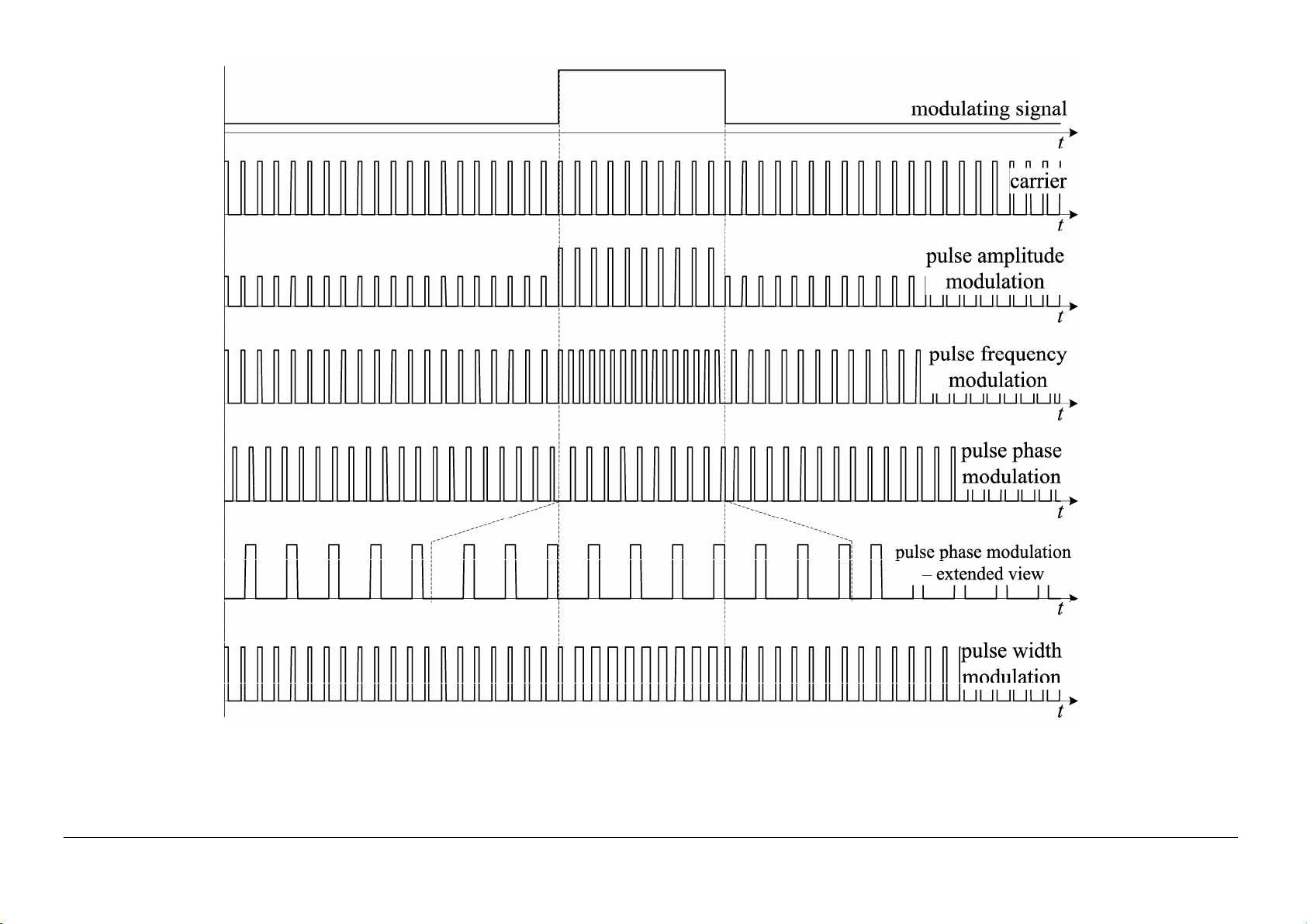
• Modulation – altering one or more of the parameters (amplitude, frequency, phase, pulse width) of the
carrier in correspondence with the modulating signal.
• Demodulation – extraction of modulating signal from modulated signal; reverse operation to modulation.
• Continuous wave modulation – when the carrier is sinusoidal.
• Pulse modulation – the carrier is pulse train. RF Signals and Systems
1. Introduction. Communication Systems 9/13
Figure 2. Examples of the basic continuous modulations. RF Signals and Systems
1. Introduction. Communication Systems 10/13
Figure 3. Examples of the basic pulse modulations. RF Signals and Systems
1. Introduction. Communication Systems 11/13
4.2. Modulation Benefits and Applications
4.3. Analog and Digital Communications
• Analog communication systems: the
• Modulation for efficient transmission;
informative signal is transmitted in continuous
• Modulation to overcome hardware form. limitation;
• Digital communication system: the
informative signal is represented as a sequence
• Modulation to overcome noise and
of limited set of symbols (digits) and these interference;
symbols are transmitted via the channel by
• Modulation for frequency assignment
applying of and appropriate modulation. The
input signal must be sampled if it enters in
• Modulation for multiplexing: frequency analog form.
division; time division, multiple access
• Basic advantages of the digital communication
• Coding methods and benefits systems:
¾ better resistivity against the noise;
¾ allows the use of effective coding methods;
¾ more flexible signal handling suggested by
digital signal processing methods
• However the front end of radiofrequency (RF)
communication systems are always analog
since signals are existing only in analog form. RF Signals and Systems
1. Introduction. Communication Systems 12/13 References:
1. [1] A. Bruce Carlson, P. B. Crilly, J. C. Rutledge, Communication Systems, 4th ed., McGraw-Hill, 2002, ISBN 0-07-011127-8. RF Signals and Systems
1. Introduction. Communication Systems 13/13
Document Outline
- 1. Information, Messages, Signals
- 2. Elements of a Communication System
- 3. Fundamental Limitations in Communications
- 3.1. Limitations Due to Technological Problems
- 3.2. Fundamental Physical Limitations
- 1.
- 4. Modulation
Tài liệu liên quan:
-
Bài giảng Nhập môn Kỹ thuật Môi trường | Đại học Bách Khoa Hà Nội
34 17 -

Bài Tập Kỹ Thuật (Có Tạm Án) | Đại học Bách Khoa Hà Nội
397 199 -

Tổng hợp bài tập ôn tập LTTT_ Đặng Văn Chuyết| Môn Nhập môn kỹ thuật truyền thông| Trường Đại học Bách Khoa Hà Nội
381 191 -

Giáo trình Lý thuyết truyền thông_PGS.TS. Nguyễn Bình| Môn Nhập môn kỹ thuật truyền thông| Trường Đại học Bách Khoa Hà Nội
376 188 -
Giáo trình Lý thuyết truyền thông_TS. Lê Quyết Thắng, ThS. Phan Tấn Tài & Ks. Dương Văn Hiếu| Môn Nhập môn kỹ thuật truyền thông| Trường Đại học Bách Khoa Hà Nội
1.3 K 666