SLIDE Week 10 + 11 – Lecture 10 – Pipelined Processor Design (cont) Kiến Trúc Máy Tính | Trường Đại học Công nghệ, Đại học Quốc gia Hà Nội
SLIDE Week 10 + 11 – Lecture 10 – Pipelined Processor Design (cont) Kiến Trúc Máy Tính | Trường Đại học Công nghệ, Đại học Quốc gia Hà Nội . Tài liệu được sưu tầm và biên soạn dưới dạng PDF gồm 42 trang giúp bạn tham khảo, củng cố kiến thức và ôn tập đạt kết quả cao trong kỳ thi sắp tới. Mời bạn đọc đón xem!
Môn: Kiến Trúc Máy Tính (UET) 19 tài liệu
Trường: Trường Đại học Công nghệ, Đại học Quốc gia Hà Nội 804 tài liệu
Tác giả:

Preview text:
ELT3047 Computer Architecture
Lecture 10: Pipelined Processor Design (cont.) Hoang Gia Hung
Faculty of Electronics and Telecommunications
University of Engineering and Technology, VNU Hanoi Last lecture review ❑ Multi-cycle processor
➢ Use one clock cycle per step → shorter clock cycle time
➢ Higher performance over single-cycle processor due to less waste ❑ Pipeline processor design
➢ Employs instruction parallelism: process the next instruction on the
resources available when current instructions move to subsequent phases.
➢ Speedup is due to increased throughput: once the pipeline is full, CPI=1.
➢ Datapath is derived from single-cycle case with additional buffer registers
➢ Some control signals are moved along the pipeline via inter-stage buffers.
❑ As the instruction pipeline is not ideal, various issues may occur
including structural, data, and control hazards.
❑ Today’s lecture: handling of pipeline hazards Pipeline hazards ❑ Issues in pipeline design
➢ structural hazards: attempt to use the same resource by two different instructions at the same time
➢ data hazards: attempt to use data before it is ready, e.g. an instruction’s
source operand(s) are produced by a prior instruction still in the pipeline
➢ control hazards: attempt to make a decision about program control flow
before the condition has been evaluated and the new PC target address
calculated (e.g. branch and jump instructions, exceptions)
❑ Serious problems, cannot be ignored
❑ Design objectives: keeping the pipeline correct, moving, and
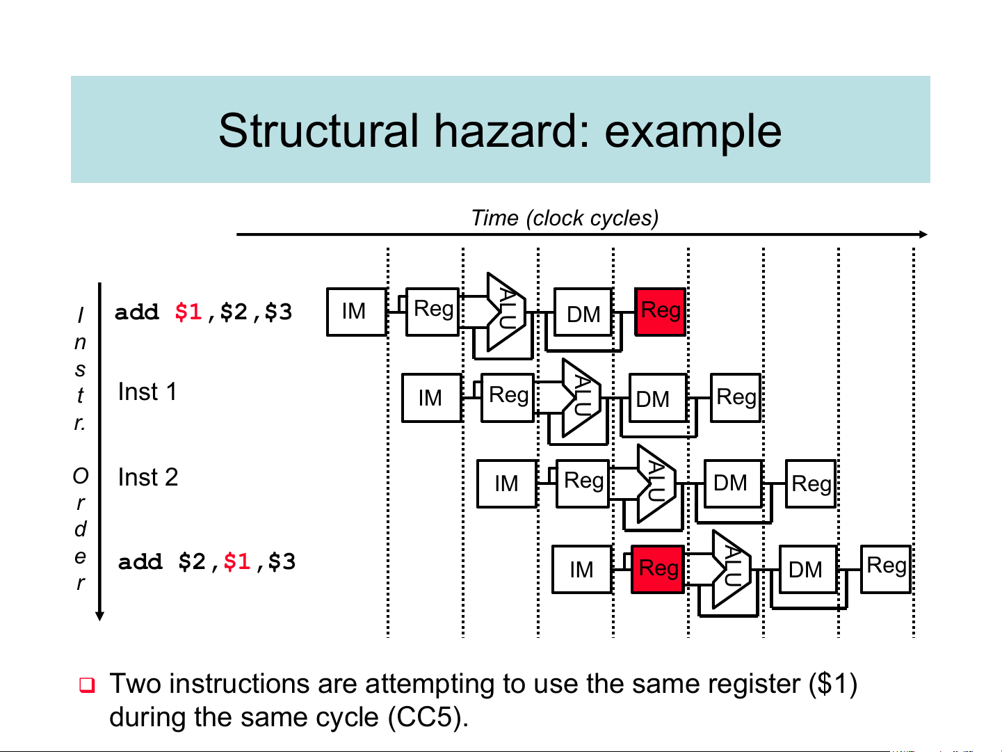
full in the presence of events that disrupt pipeline flow. Structural hazard: example Time (clock cycles) ALU I add $1,$2,$3 IM Reg DM Reg n s ALU t Inst 1 IM Reg DM Reg r. ALU O Inst 2 IM Reg DM Reg r d ALU e add $2,$1,$3 IM Reg DM Reg r
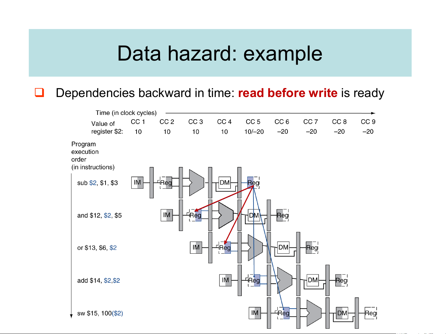
❑ Two instructions are attempting to use the same register ($1) during the same cycle (CC5). Data hazard: example
❑ Dependencies backward in time: read before write is ready Hazard handling methods
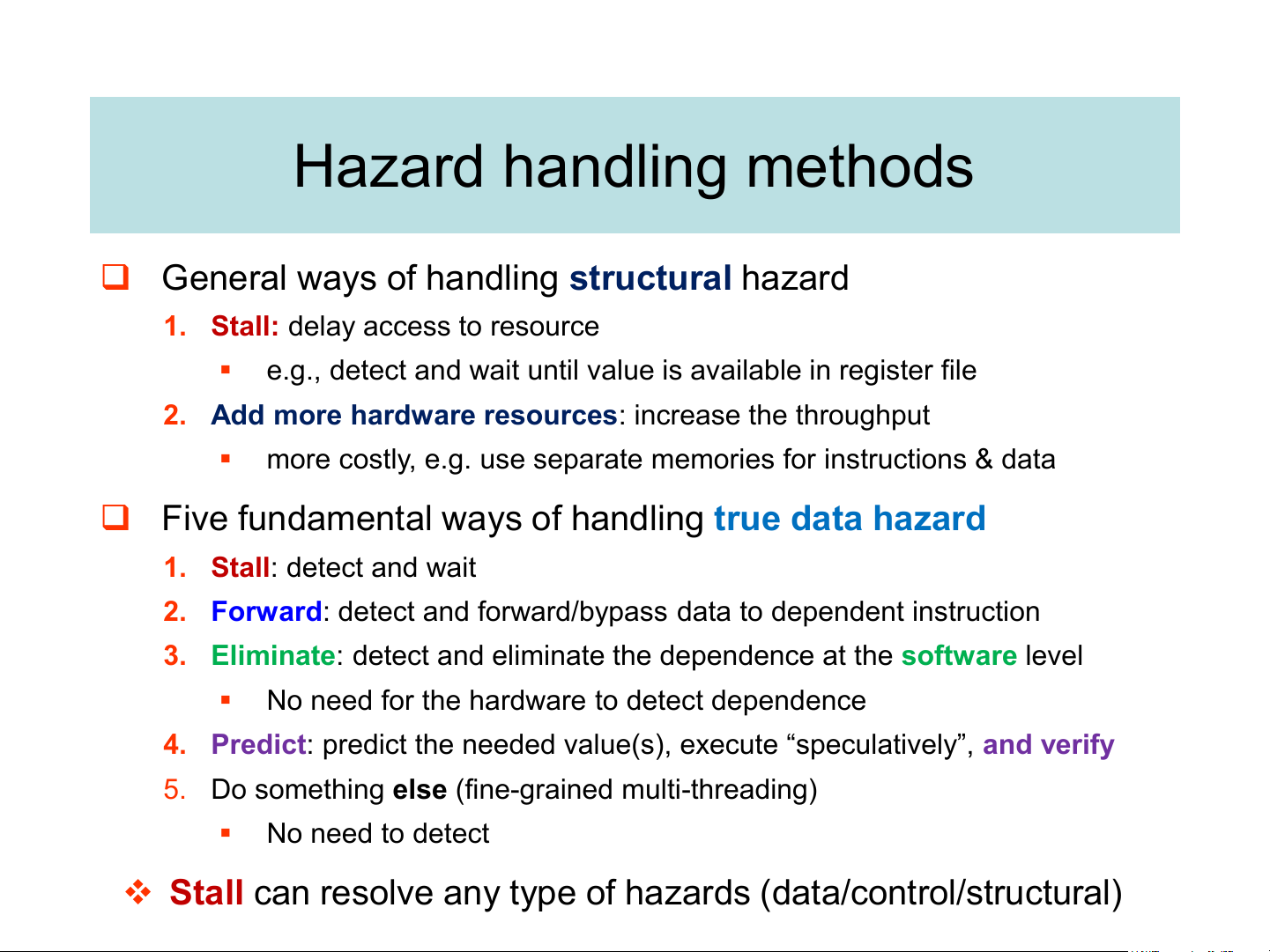
❑ General ways of handling structural hazard
1. Stall: delay access to resource ▪
e.g., detect and wait until value is available in register file
2. Add more hardware resources: increase the throughput ▪
more costly, e.g. use separate memories for instructions & data
❑ Five fundamental ways of handling true data hazard
1. Stall: detect and wait
2. Forward: detect and forward/bypass data to dependent instruction
3. Eliminate: detect and eliminate the dependence at the software level ▪
No need for the hardware to detect dependence
4. Predict: predict the needed value(s), execute “speculatively”, and verify
5. Do something else (fine-grained multi-threading) ▪ No need to detect
❖ Stall can resolve any type of hazards (data/control/structural)
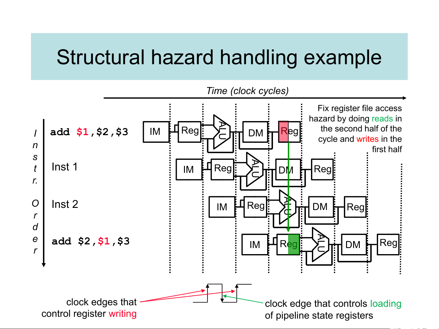
Structural hazard handling example Time (clock cycles) Fix register file access ALU hazard by doing reads in the second half of the I add $1,$2,$3 IM Reg DM Reg cycle and writes in the n first half s ALU t Inst 1 IM Reg DM Reg r. ALU O Inst 2 IM Reg DM Reg r d ALU e add $2,$1,$3 IM Reg DM Reg r clock edges that
clock edge that controls loading control register writing of pipeline state registers
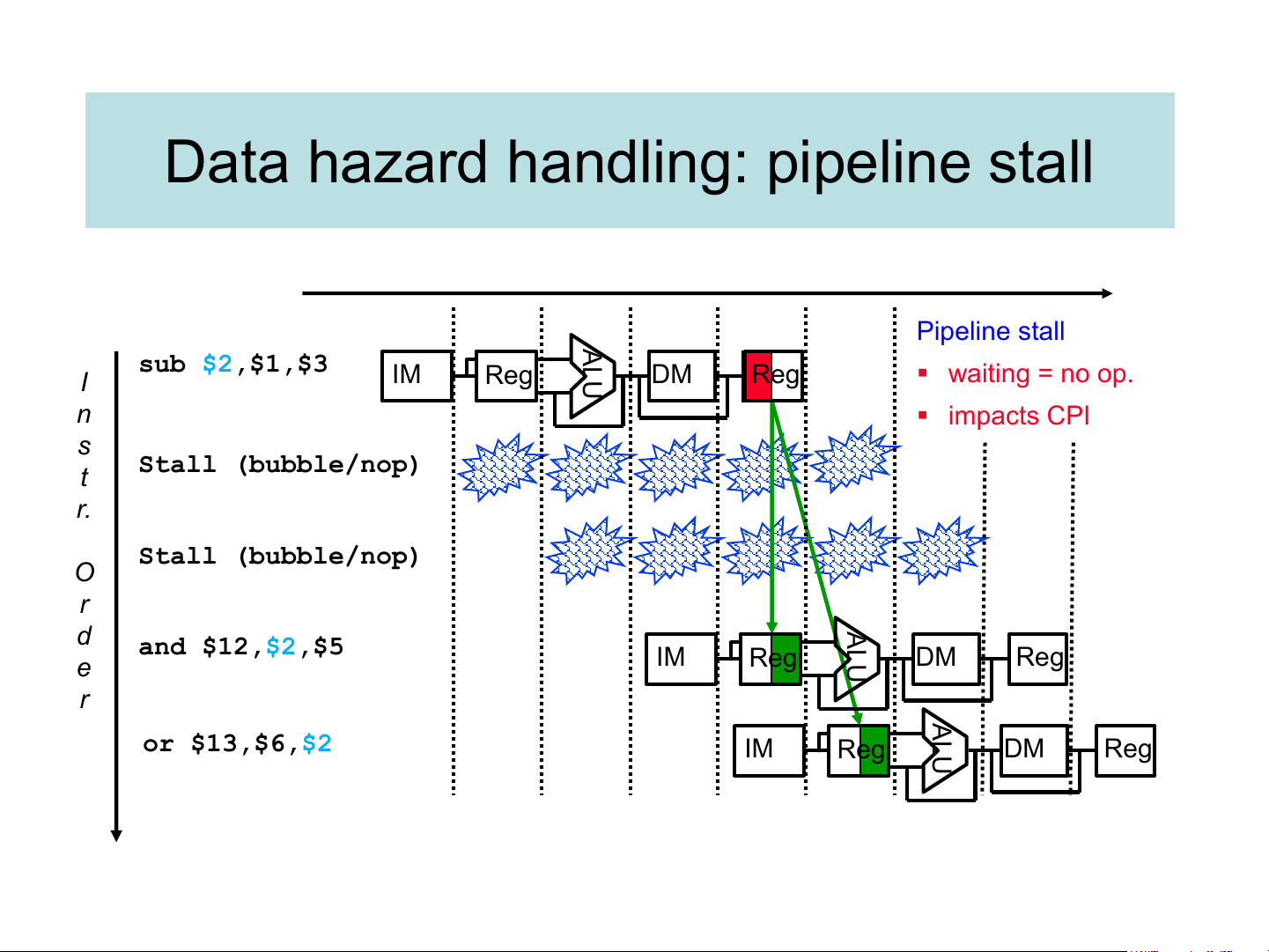
Data hazard handling: pipeline stall A Pipeline stall sub $2,$1,$3 L I IM Reg U DM Reg ▪ waiting = no op. n ▪ impacts CPI s Stall (bubble/nop) t r. Stall (bubble/nop) O r AL d and $12,$2,$5 IM Reg U e DM Reg r A or $13,$6,$2 L IM Reg U DM Reg
Data Forwarding/Bypassing: overview
Forwarding results as soon as they are
available to where they are needed. ▪
Forwarding paths are valid only if the
destination stage is later in time than the source stage. ▪ Take the result from the
earliest point that exists in any of the pipeline state
registers and forward it to
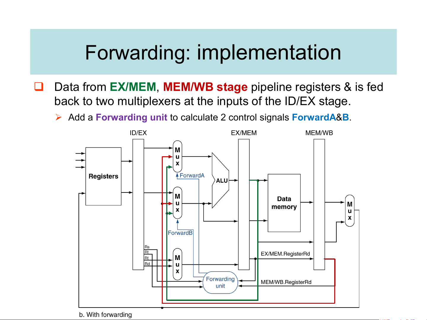
the functional unit (ALU). Forwarding: implementation
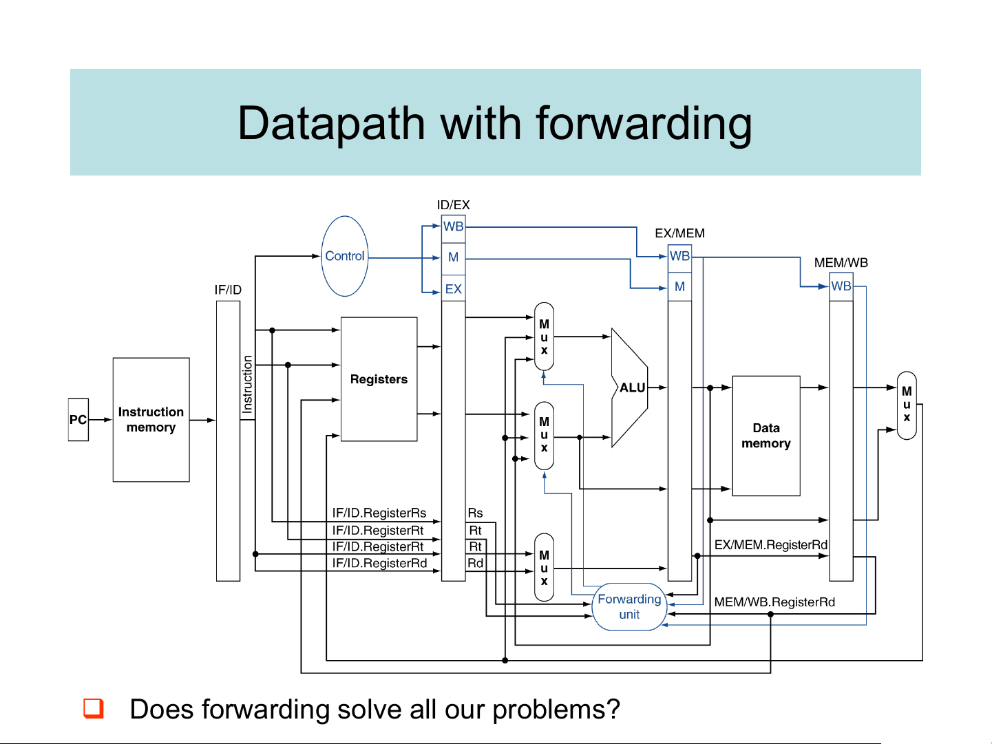
❑ Data from EX/MEM, MEM/WB stage pipeline registers & is fed
back to two multiplexers at the inputs of the ID/EX stage.
➢ Add a Forwarding unit to calculate 2 control signals ForwardA&B.
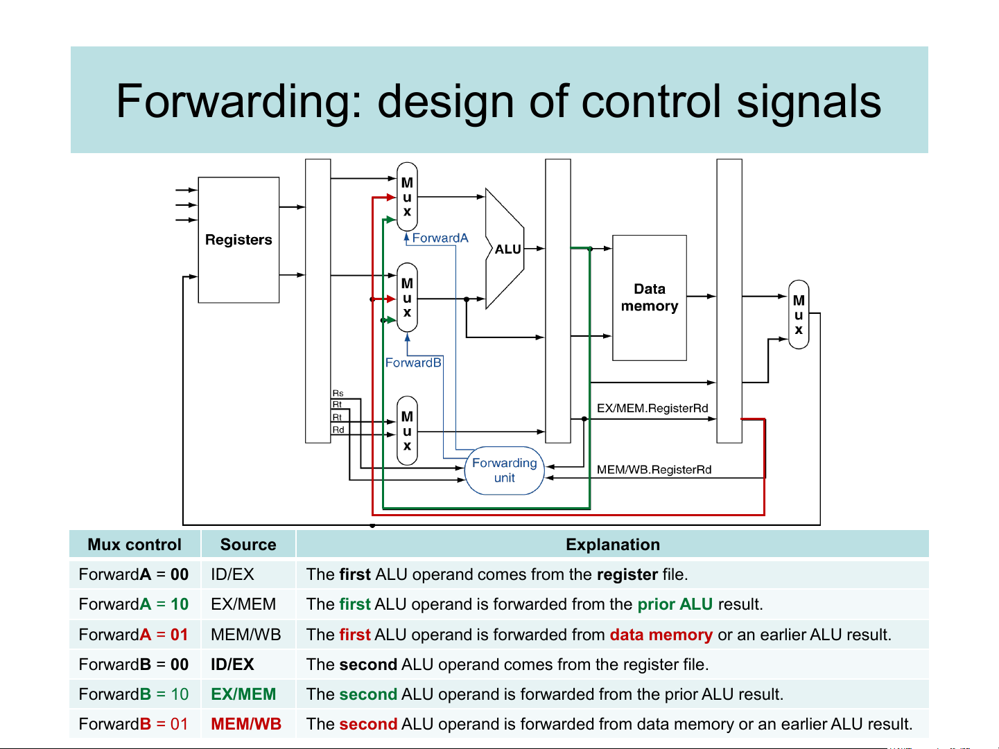
Forwarding: design of control signals Mux control Source Explanation ForwardA = 00 ID/EX
The first ALU operand comes from the register file. ForwardA = 10 EX/MEM
The first ALU operand is forwarded from the prior ALU result. ForwardA = 01 MEM/WB
The first ALU operand is forwarded from data memory or an earlier ALU result. ForwardB = 00 ID/EX
The second ALU operand comes from the register file. ForwardB = 10 EX/MEM
The second ALU operand is forwarded from the prior ALU result. ForwardB = 01 MEM/WB
The second ALU operand is forwarded from data memory or an earlier ALU result. Forwarding conditions
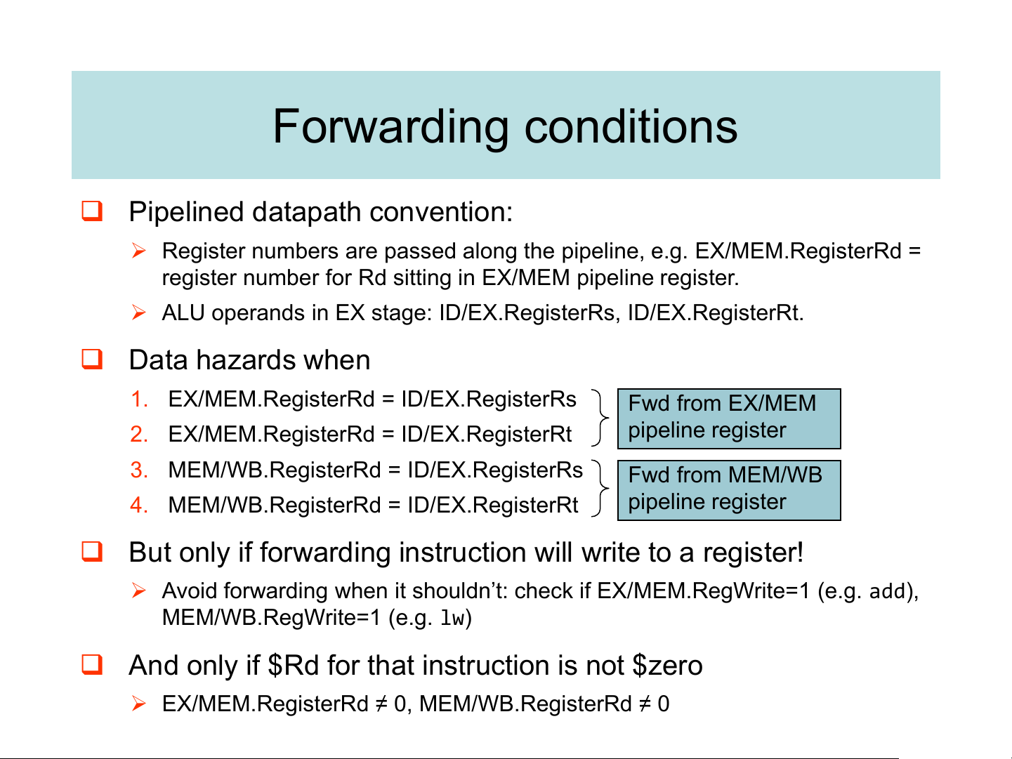
❑ Pipelined datapath convention:
➢ Register numbers are passed along the pipeline, e.g. EX/MEM.RegisterRd =
register number for Rd sitting in EX/MEM pipeline register.
➢ ALU operands in EX stage: ID/EX.RegisterRs, ID/EX.RegisterRt. ❑ Data hazards when
1. EX/MEM.RegisterRd = ID/EX.RegisterRs Fwd from EX/MEM
2. EX/MEM.RegisterRd = ID/EX.RegisterRt pipeline register
3. MEM/WB.RegisterRd = ID/EX.RegisterRs Fwd from MEM/WB
4. MEM/WB.RegisterRd = ID/EX.RegisterRt pipeline register
❑ But only if forwarding instruction will write to a register!
➢ Avoid forwarding when it shouldn’t: check if EX/MEM.RegWrite=1 (e.g. add), MEM/WB.RegWrite=1 (e.g. lw)
❑ And only if $Rd for that instruction is not $zero
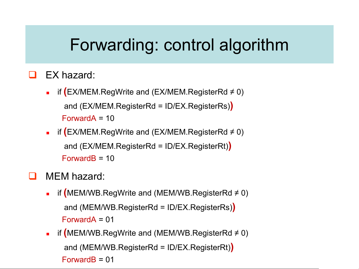
➢ EX/MEM.RegisterRd ≠ 0, MEM/WB.RegisterRd ≠ 0 Forwarding: control algorithm ❑ EX hazard: ◼
if (EX/MEM.RegWrite and (EX/MEM.RegisterRd ≠ 0)
and (EX/MEM.RegisterRd = ID/EX.RegisterRs)) ForwardA = 10 ◼
if (EX/MEM.RegWrite and (EX/MEM.RegisterRd ≠ 0)
and (EX/MEM.RegisterRd = ID/EX.RegisterRt)) ForwardB = 10 ❑ MEM hazard: ◼
if (MEM/WB.RegWrite and (MEM/WB.RegisterRd ≠ 0)
and (MEM/WB.RegisterRd = ID/EX.RegisterRs)) ForwardA = 01 ◼
if (MEM/WB.RegWrite and (MEM/WB.RegisterRd ≠ 0)
and (MEM/WB.RegisterRd = ID/EX.RegisterRt)) ForwardB = 01
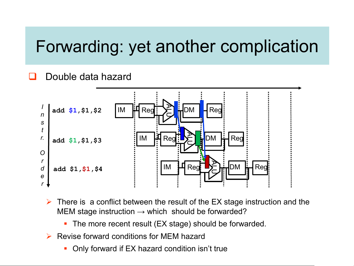
Forwarding: yet another complication ❑ Double data hazard ALU I add $1,$1,$2 IM Reg DM Reg n s t ALU r. add $1,$1,$3 IM Reg DM Reg O ALU r d IM Reg DM Reg add $1,$1,$4 e r
➢ There is a conflict between the result of the EX stage instruction and the
MEM stage instruction → which should be forwarded?
▪ The more recent result (EX stage) should be forwarded.
➢ Revise forward conditions for MEM hazard
▪ Only forward if EX hazard condition isn’t true
Forwarding: revised control algorithm
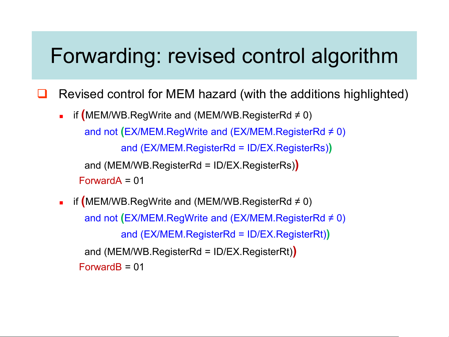
❑ Revised control for MEM hazard (with the additions highlighted) ◼
if (MEM/WB.RegWrite and (MEM/WB.RegisterRd ≠ 0)
and not (EX/MEM.RegWrite and (EX/MEM.RegisterRd ≠ 0)
and (EX/MEM.RegisterRd = ID/EX.RegisterRs))
and (MEM/WB.RegisterRd = ID/EX.RegisterRs)) ForwardA = 01 ◼
if (MEM/WB.RegWrite and (MEM/WB.RegisterRd ≠ 0)
and not (EX/MEM.RegWrite and (EX/MEM.RegisterRd ≠ 0)
and (EX/MEM.RegisterRd = ID/EX.RegisterRt))
and (MEM/WB.RegisterRd = ID/EX.RegisterRt)) ForwardB = 01 Datapath with forwarding
❑ Does forwarding solve all our problems? Load-Use Data Hazard
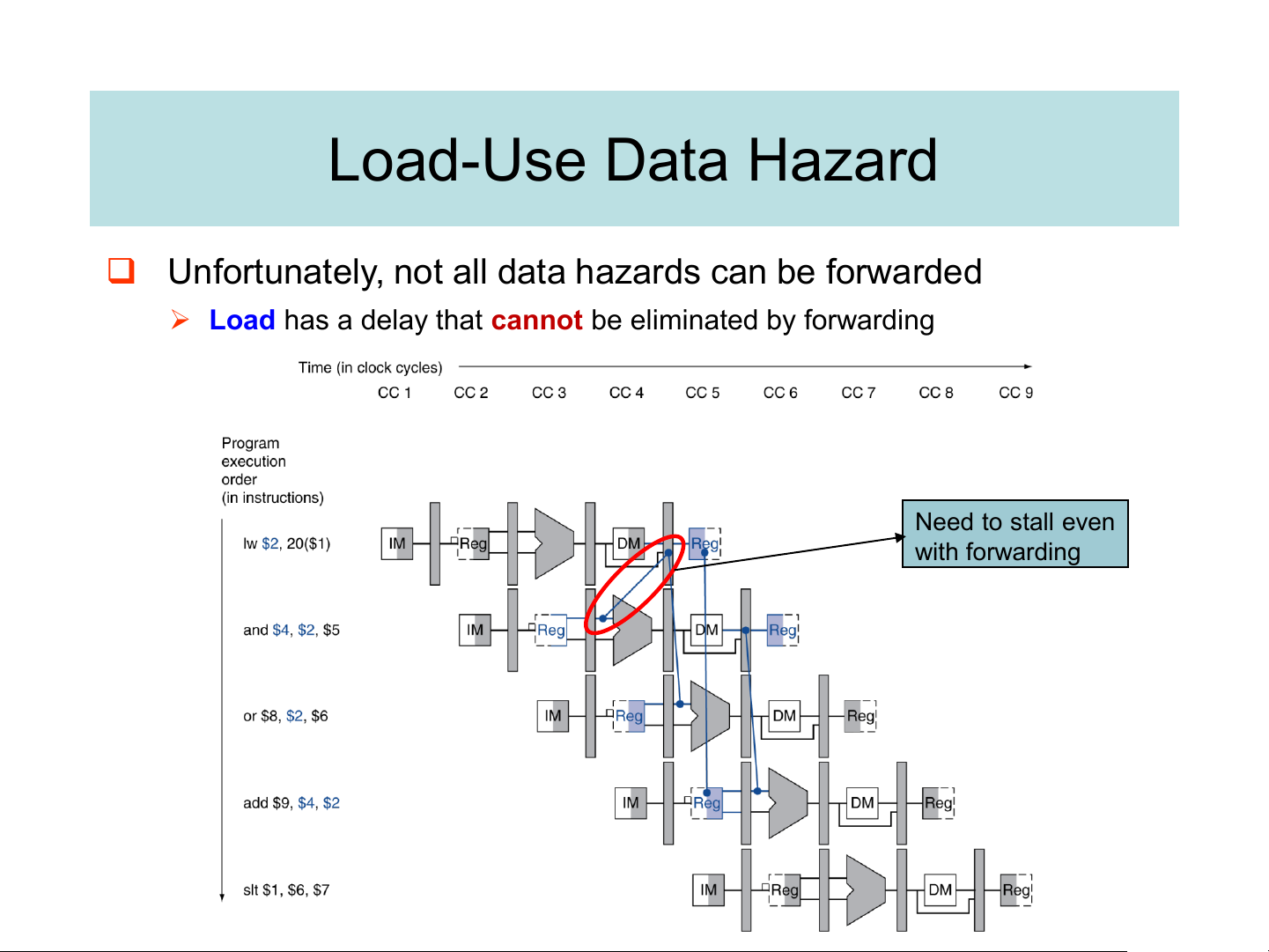
❑ Unfortunately, not all data hazards can be forwarded
➢ Load has a delay that cannot be eliminated by forwarding Need to stall even with forwarding Load-Use Hazard Detection
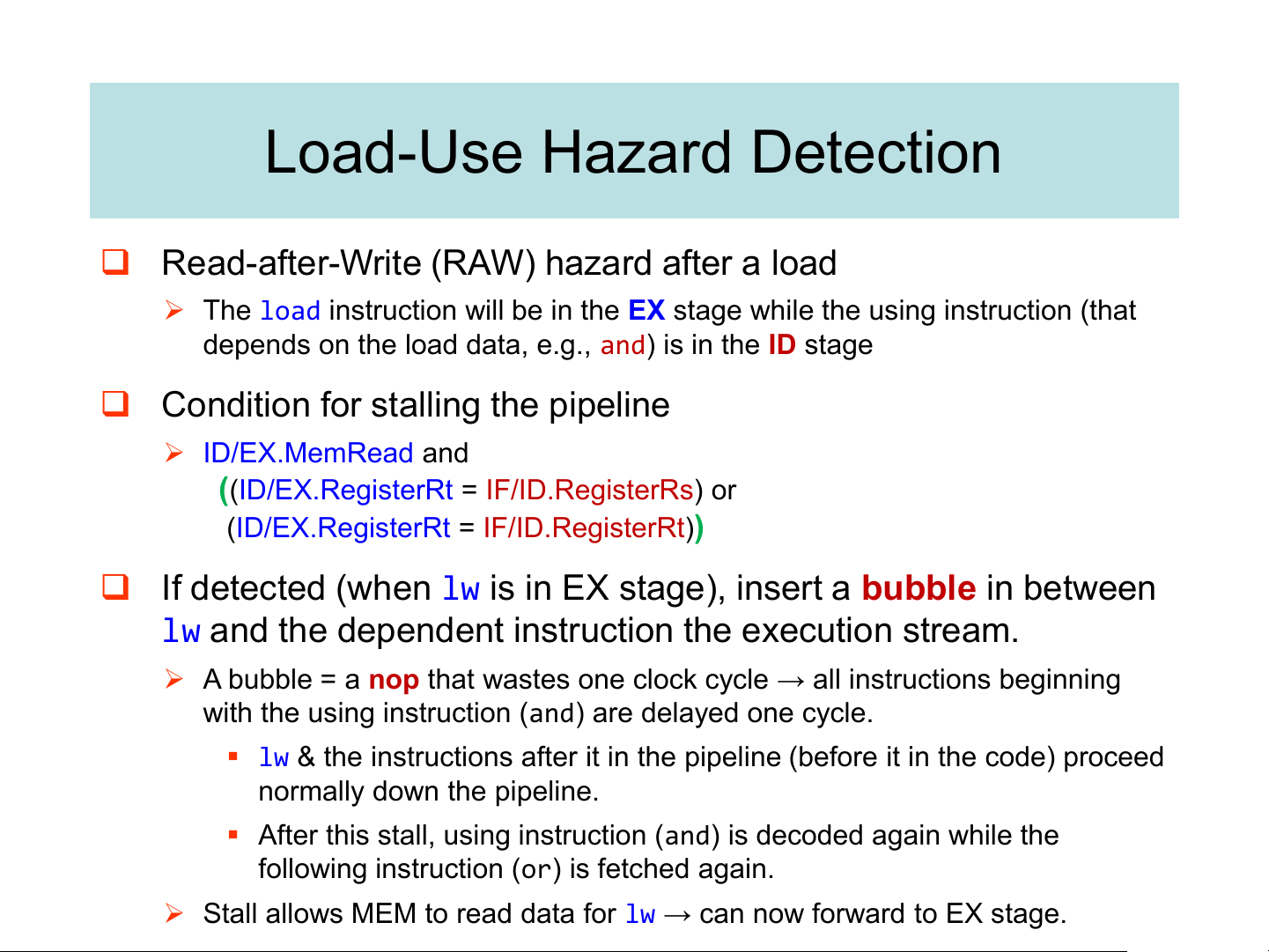
❑ Read-after-Write (RAW) hazard after a load
➢ The load instruction will be in the EX stage while the using instruction (that
depends on the load data, e.g., and) is in the ID stage
❑ Condition for stalling the pipeline ➢ ID/EX.MemRead and
((ID/EX.RegisterRt = IF/ID.RegisterRs) or
(ID/EX.RegisterRt = IF/ID.RegisterRt))
❑ If detected (when lw is in EX stage), insert a bubble in between
lw and the dependent instruction the execution stream.
➢ A bubble = a nop that wastes one clock cycle → all instructions beginning
with the using instruction (and) are delayed one cycle.
▪ lw & the instructions after it in the pipeline (before it in the code) proceed normally down the pipeline.
▪ After this stall, using instruction (and) is decoded again while the
following instruction (or) is fetched again.
➢ Stall allows MEM to read data for lw → can now forward to EX stage.
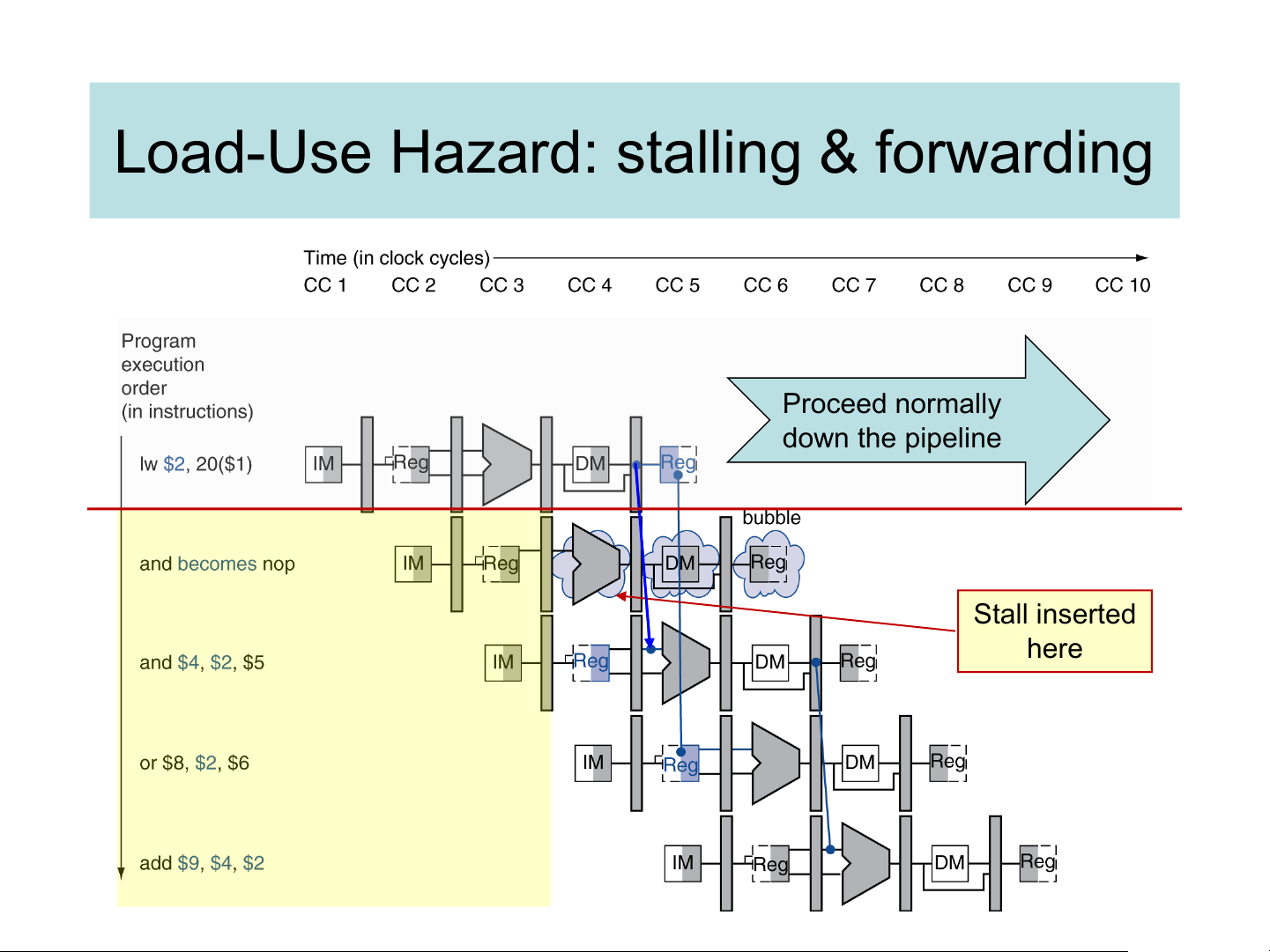
Load-Use Hazard: stalling & forwarding Proceed normally down the pipeline Stall inserted here Stall Hardware
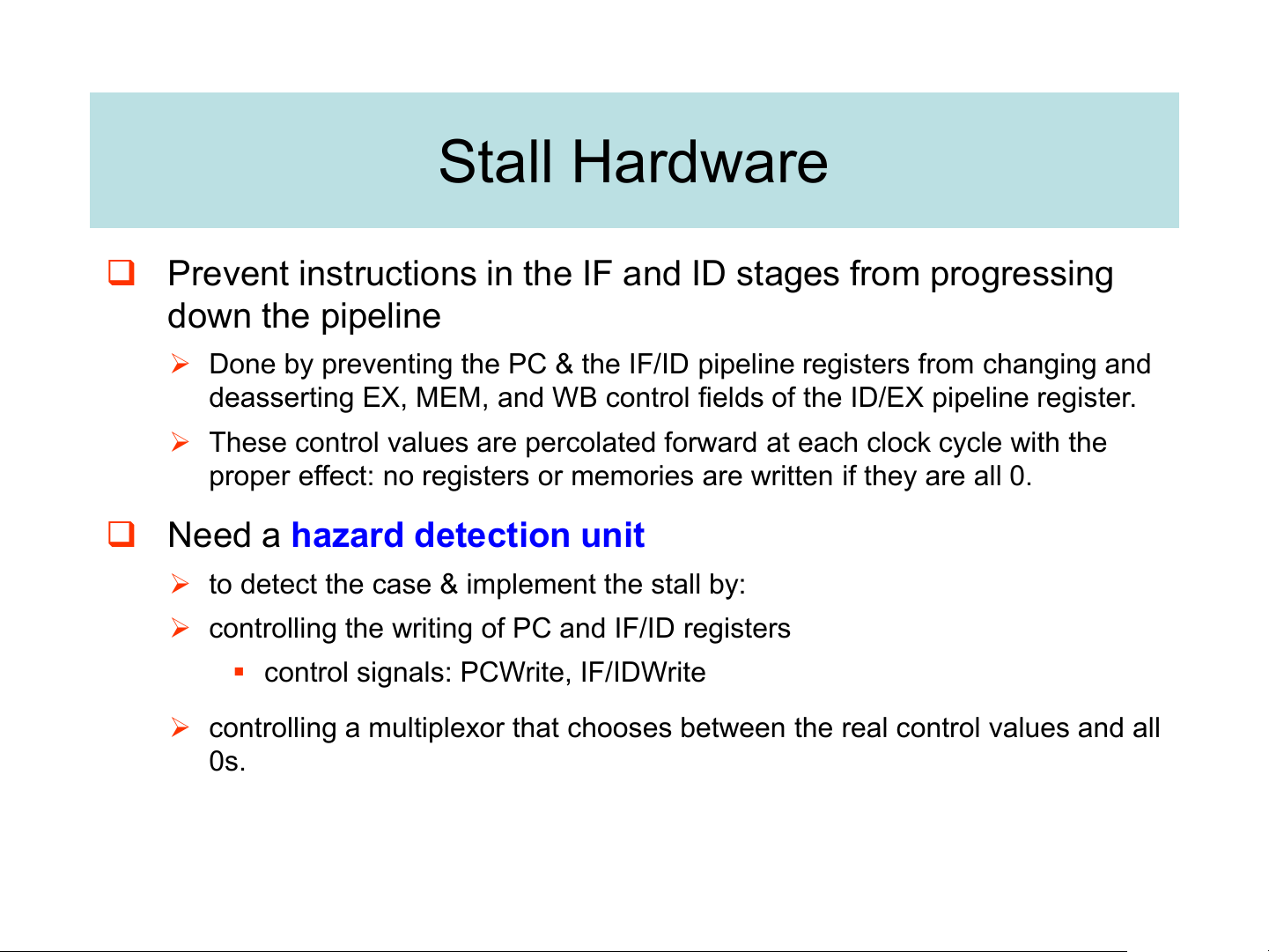
❑ Prevent instructions in the IF and ID stages from progressing down the pipeline
➢ Done by preventing the PC & the IF/ID pipeline registers from changing and
deasserting EX, MEM, and WB control fields of the ID/EX pipeline register.
➢ These control values are percolated forward at each clock cycle with the
proper effect: no registers or memories are written if they are all 0.
❑ Need a hazard detection unit
➢ to detect the case & implement the stall by:
➢ controlling the writing of PC and IF/ID registers
▪ control signals: PCWrite, IF/IDWrite
➢ controlling a multiplexor that chooses between the real control values and all 0s.
Tài liệu liên quan:
-
TỔNG HỢP ĐỀ THI KTMT
36 18 -
Đề thi Kiến trúc máy tính đề số 2 năm học 2020-2021 | Trường Đại học Công nghệ, Đại học Quốc gia Hà Nội
235 118 -
Đề thi và đáp án Kiến trúc máy tính giữa kỳ 1 năm học 2021-2022 | Trường Đại học Công nghệ, Đại học Quốc gia Hà Nội
237 119 -

Đề thi Kiến trúc máy tính CLC giữa kỳ 1 năm học 2022-2023 | Trường Đại học Công nghệ, Đại học Quốc gia Hà Nội
191 96 -
Đề thi Kiến trúc máy tính CLC lần 2 giữa kỳ 1 năm học 2022-2023 | Trường Đại học Công nghệ, Đại học Quốc gia Hà Nội
148 74