SLIDE Week 3 – Lecture 3 – ISA design princples Kiến Trúc Máy Tính | Trường Đại học Công nghệ, Đại học Quốc gia Hà Nội
SLIDE Week 3 – Lecture 3 – ISA design princples Kiến Trúc Máy Tính | Trường Đại học Công nghệ, Đại học Quốc gia Hà Nội. Tài liệu được sưu tầm và biên soạn dưới dạng PDF gồm 32 trang giúp bạn tham khảo, củng cố kiến thức và ôn tập đạt kết quả cao trong kỳ thi sắp tới. Mời bạn đọc đón xem!
Môn: Kiến Trúc Máy Tính (UET) 19 tài liệu
Trường: Trường Đại học Công nghệ, Đại học Quốc gia Hà Nội 762 tài liệu
Tác giả:


Preview text:
ELT3047 Computer Architecture
Lesson 3: ISA design principles Hoang Gia Hung
Faculty of Electronics and Telecommunications
University of Engineering and Technology, VNU Hanoi Last lecture review
❑ Various measures for computer performance
➢ Execution time: the best performance measure for designers
➢ MIPS/MFLOPS: easy to understand but contains many drawbacks
➢ Benchmarks: use real applications – best performance measure for users
❑ Factors affecting execution time ➢ Instruction counts ➢ CPI ➢ Clock cycle time (rate)
➢ Power is a limiting factor (the power wall)
❑ Amdahl’s law of diminishing returns
➢ Improvement of one aspect is usually not proportional to improvement in overall performance.
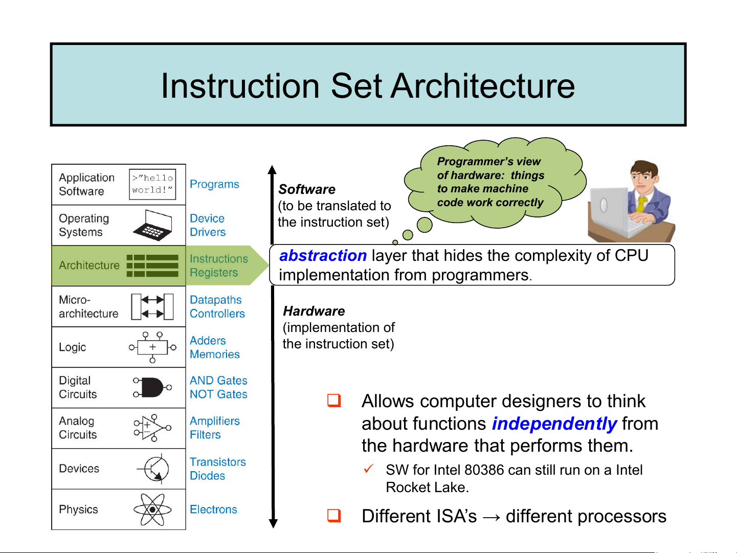
❑ Today’s lecture: ISA design principles Instruction Set Architecture Programmer’s view of hardware: things Software to make machine (to be translated to
code work correctly the instruction set)
abstraction layer that hides the complexity of CPU
implementation from programmers. Hardware (implementation of the instruction set)
❑ Allows computer designers to think
about functions independently from
the hardware that performs them.
✓ SW for Intel 80386 can still run on a Intel Rocket Lake.
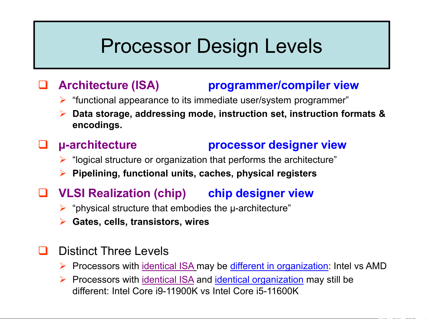
❑ Different ISA’s → different processors Processor Design Levels ❑ Architecture (ISA)
programmer/compiler view
➢ “functional appearance to its immediate user/system programmer”
➢ Data storage, addressing mode, instruction set, instruction formats & encodings. ❑ µ-architecture processor designer view
➢ “logical structure or organization that performs the architecture”
➢ Pipelining, functional units, caches, physical registers
❑ VLSI Realization (chip) chip designer view
➢ “physical structure that embodies the µ-architecture”
➢ Gates, cells, transistors, wires ❑ Distinct Three Levels
➢ Processors with identical ISA may be different in organization: Intel vs AMD
➢ Processors with identical ISA and identical organization may still be
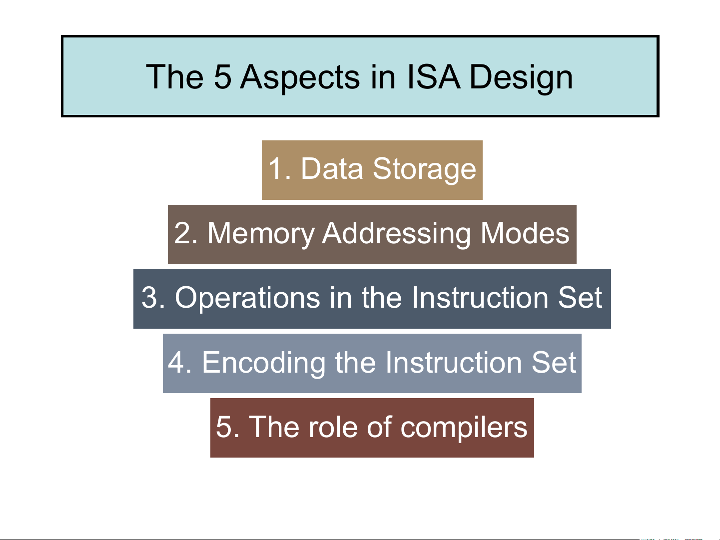
different: Intel Core i9-11900K vs Intel Core i5-11600K The 5 Aspects in ISA Design 1. Data Storage 2. Memory Addressing Modes
3. Operations in the Instruction Set
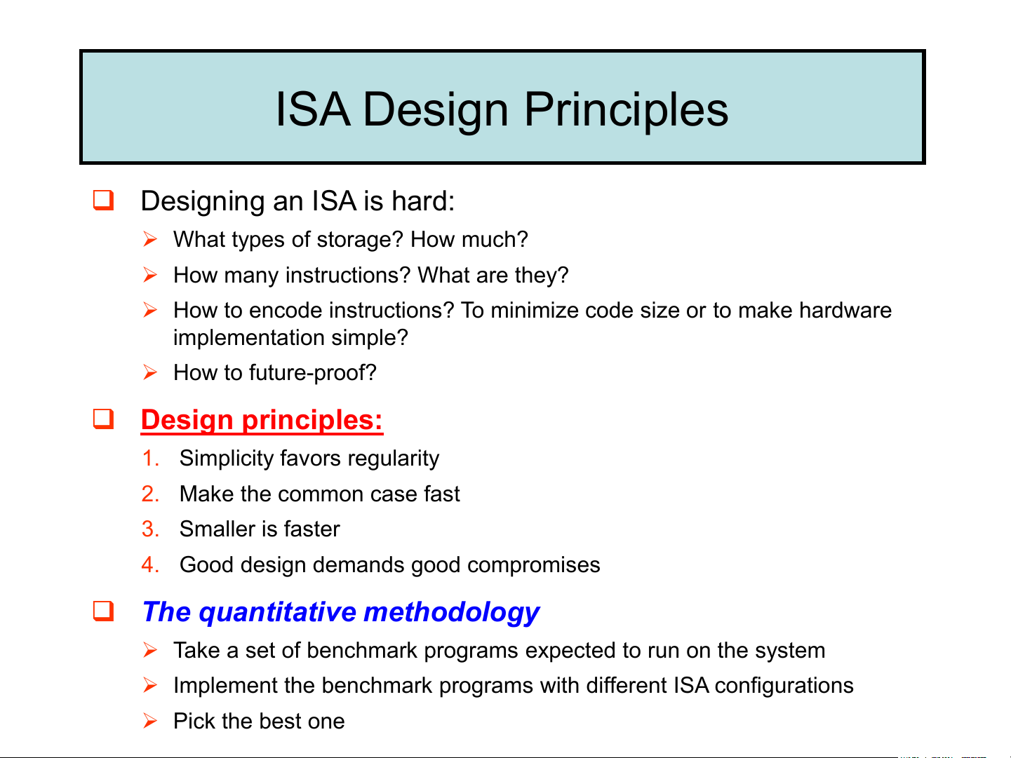
4. Encoding the Instruction Set 5. The role of compilers ISA Design Principles ❑ Designing an ISA is hard:
➢ What types of storage? How much?
➢ How many instructions? What are they?
➢ How to encode instructions? To minimize code size or to make hardware implementation simple? ➢ How to future-proof? ❑ Design principles:
1. Simplicity favors regularity 2. Make the common case fast 3. Smaller is faster
4. Good design demands good compromises
❑ The quantitative methodology
➢ Take a set of benchmark programs expected to run on the system
➢ Implement the benchmark programs with different ISA configurations ➢ Pick the best one
CISC vs RISC: the famous ISA battle
❑ Two major design philosophies for ISA:
➢ Complex instruction set computer (CISC)
➢ Reduced Instruction Set Computer (RISC) CISC RISC
Many instructions and addressing
Few instructions and addressing modes modes Single instruction performs
Simple instructions, combined by complex operation
SW to perform complex operations Smaller program size Larger program size Complex implementation
Easier to build/optimize hardware MIPS, Sun SPARC, HP PA-RISC, Intel, AMD, Cyrix IBM PowerPC
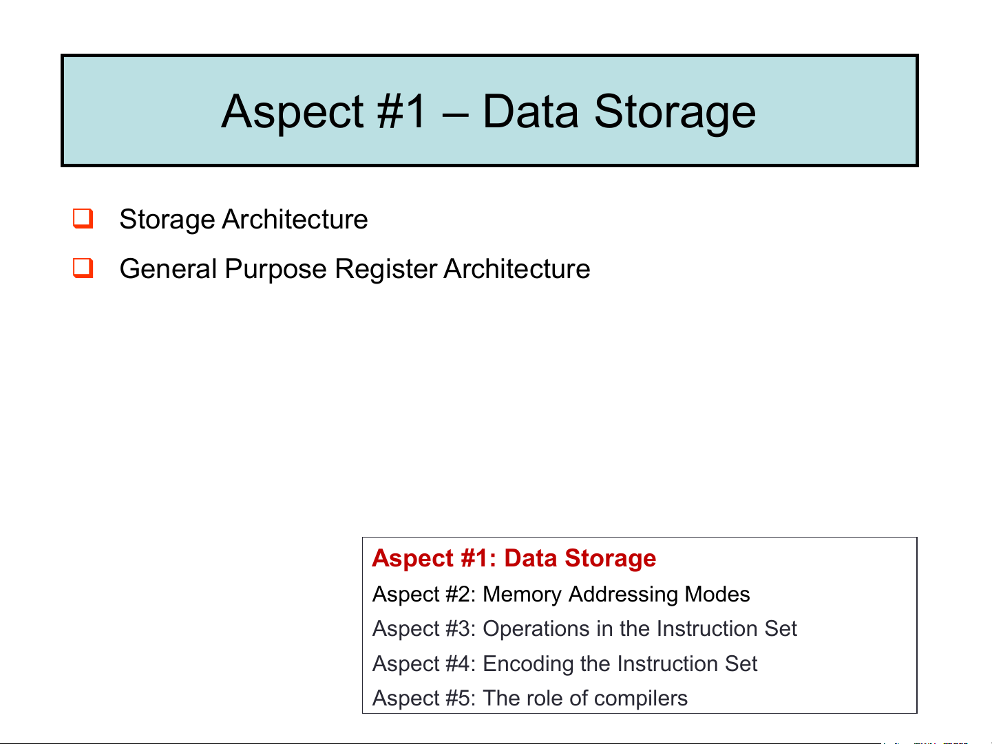
❑ This course’s case study: MIPS (RISC) Aspect #1 – Data Storage ❑ Storage Architecture
❑ General Purpose Register Architecture Aspect #1: Data Storage
Aspect #2: Memory Addressing Modes
Aspect #3: Operations in the Instruction Set
Aspect #4: Encoding the Instruction Set
Aspect #5: The role of compilers
Recap: Instruction & Instruction Set cơ bản
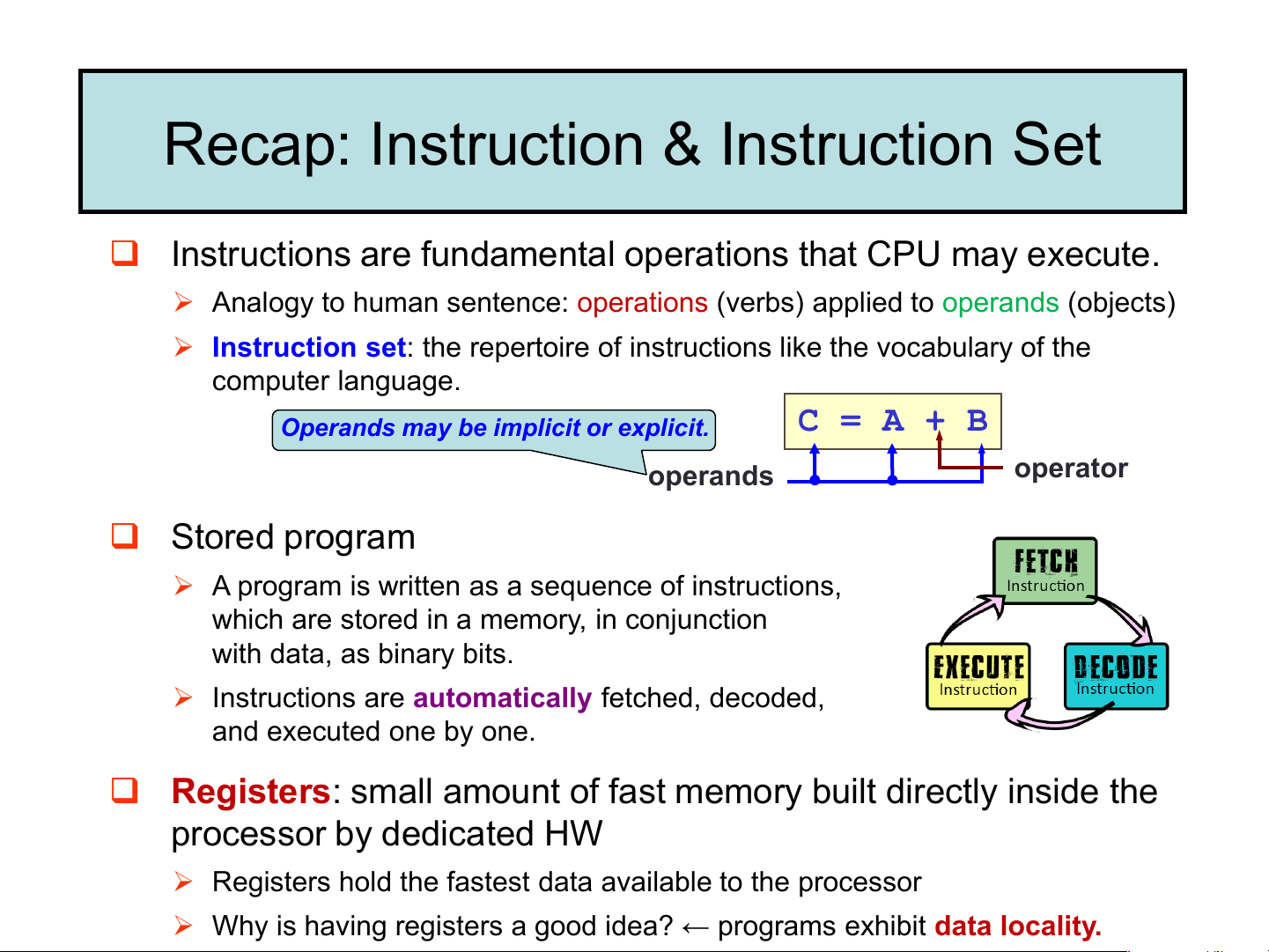
❑ Instructions are fundamental operations that CPU may execute.
➢ Analogy to human sentence: operations (verbs) applied to operands (objects)
➢ Instruction set: the repertoire of instructions like the vocabulary of the computer language.
Operands may be implicit or explicit. C = A + B operands operator ❑ Stored program
➢ A program is written as a sequence of instructions,
which are stored in a memory, in conjunction with data, as binary bits. lấy, giải mã, thực thi
➢ Instructions are automatically fetched, decoded, and executed one by one.
❑ Registers: small amount of fast memory built directly inside the processor by dedicated HW
➢ Registers hold the fastest data available to the processor
➢ Why is having registers a good idea? ← programs exhibit data locality.
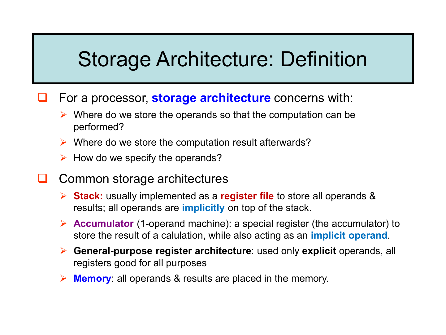
Storage Architecture: Definition
❑ For a processor, storage architecture concerns with:
➢ Where do we store the operands so that the computation can be performed?
➢ Where do we store the computation result afterwards?
➢ How do we specify the operands?
❑ Common storage architectures các loại kiến trúc bộ nhớ
➢ Stack: usually implemented as a register file to store all operands &
results; all operands are implicitly on top of the stack. kiến trúc ngăn xếp
➢ Accumulator (1-operand machine): a special register (the accumulator) to
store the result of a calulation, while also acting as an implicit operand. kiến trúc thanh ➢ ghi tích lũy
General-purpose register architecture: used only explicit operands, all
registers good for all purposes kiến trúc GPRA
➢ Memory: all operands & results are placed in the memory.
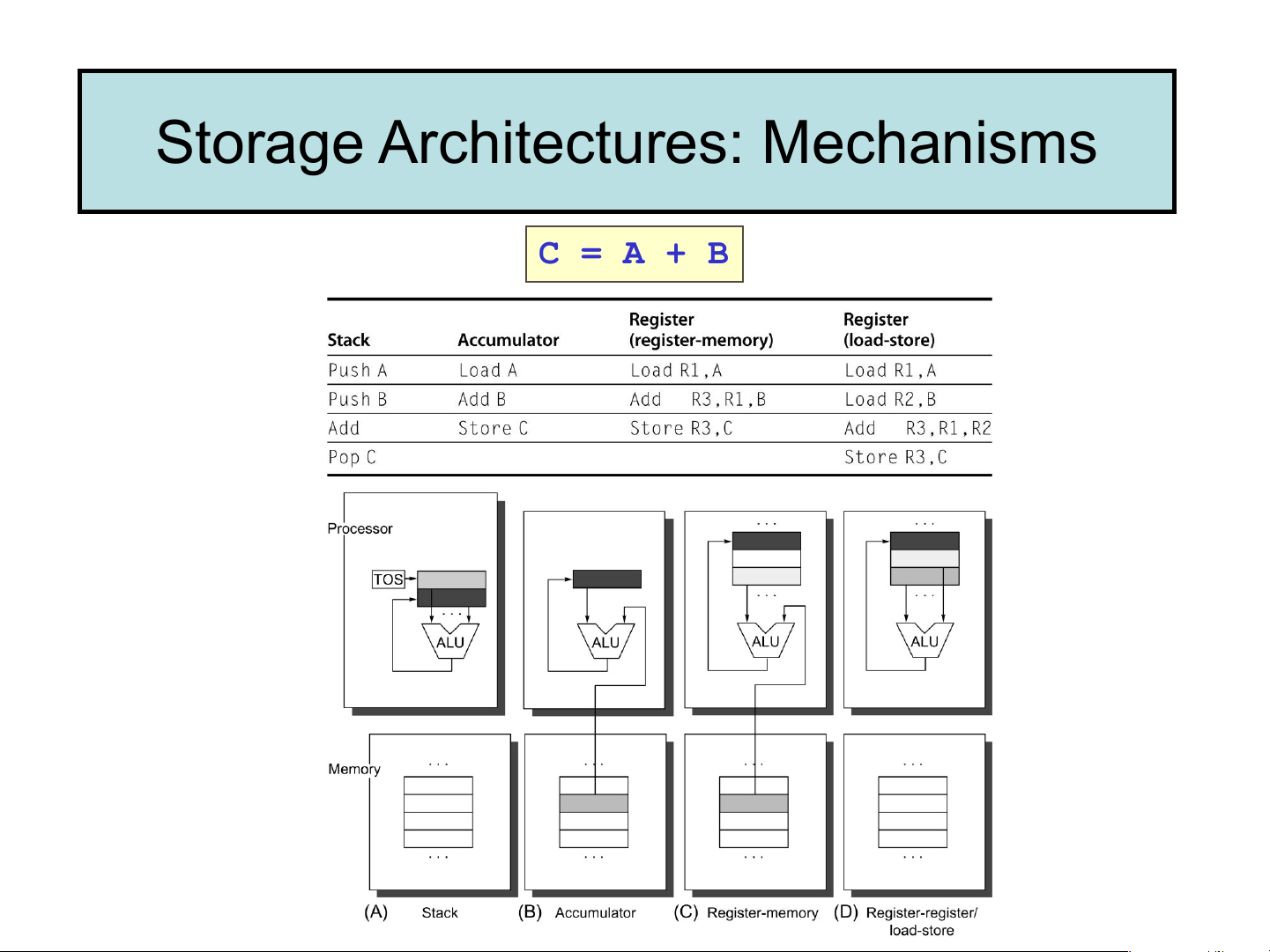
Storage Architectures: Mechanisms C = A + B Real-life implementation
❑ Stack architecture: a legacy from the “adding” machine days
➢ Top portion of the stack inside CPU; the rest in memory.
Examples: some technical handheld calculator, Z4 (by Conrad Zuse).
❑ Accumulator architecture:
➢ One operand is implicitly in the accumulator. Examples: IBM 701, DEC PDP-8.
❑ General-purpose register architecture:
➢ Register-memory architecture: one operand in memory. Examples: Motorola 68000, Intel 80386.
➢ Register-register (or load-store) architecture: both operands in registers. Examples: MIPS, DEC Alpha.
❑ Memory-memory architecture:
➢ All operands in memory. Example: DEC VAX.
Storage Architecture: GPR Architecture
❑ For modern processors (after 1980):
➢ General-Purpose Register (GPR) is the most common choice for storage design.
➢ RISC computers typically uses Register-Register (Load/Store) design E.g. MIPS, ARM
➢ CISC computers use a mixture of Register-Register and Register-Memory E.g. IA32. ❑ Reasons
➢ Registers are much faster than memory
➢ Registers are more efficient for a compiler to use
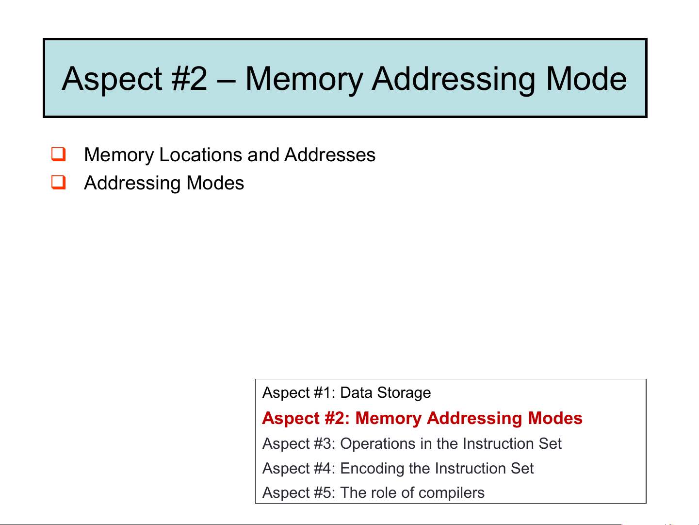
Aspect #2 – Memory Addressing Mode
❑ Memory Locations and Addresses ❑ Addressing Modes Aspect #1: Data Storage
Aspect #2: Memory Addressing Modes
Aspect #3: Operations in the Instruction Set
Aspect #4: Encoding the Instruction Set
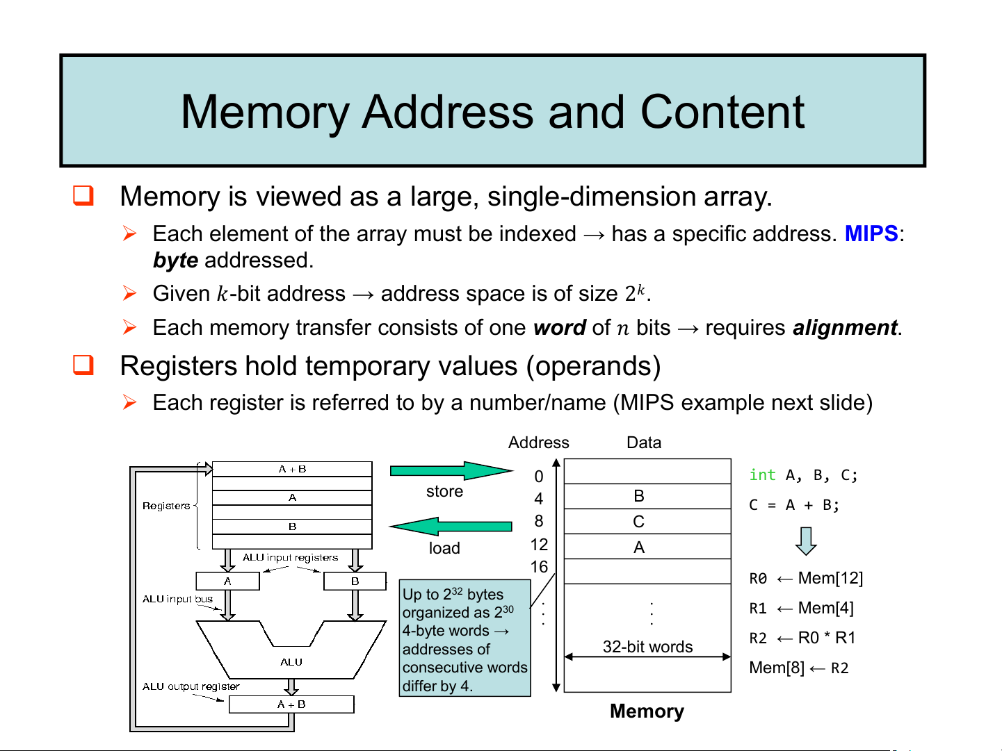
Aspect #5: The role of compilers Memory Address and Content
❑ Memory is viewed as a large, single-dimension array.
➢ Each element of the array must be indexed → has a specific address. MIPS: byte addressed.
➢ Given 𝑘-bit address → address space is of size 2𝑘.
➢ Each memory transfer consists of one word of 𝑛 bits → requires alignment.
❑ Registers hold temporary values (operands)
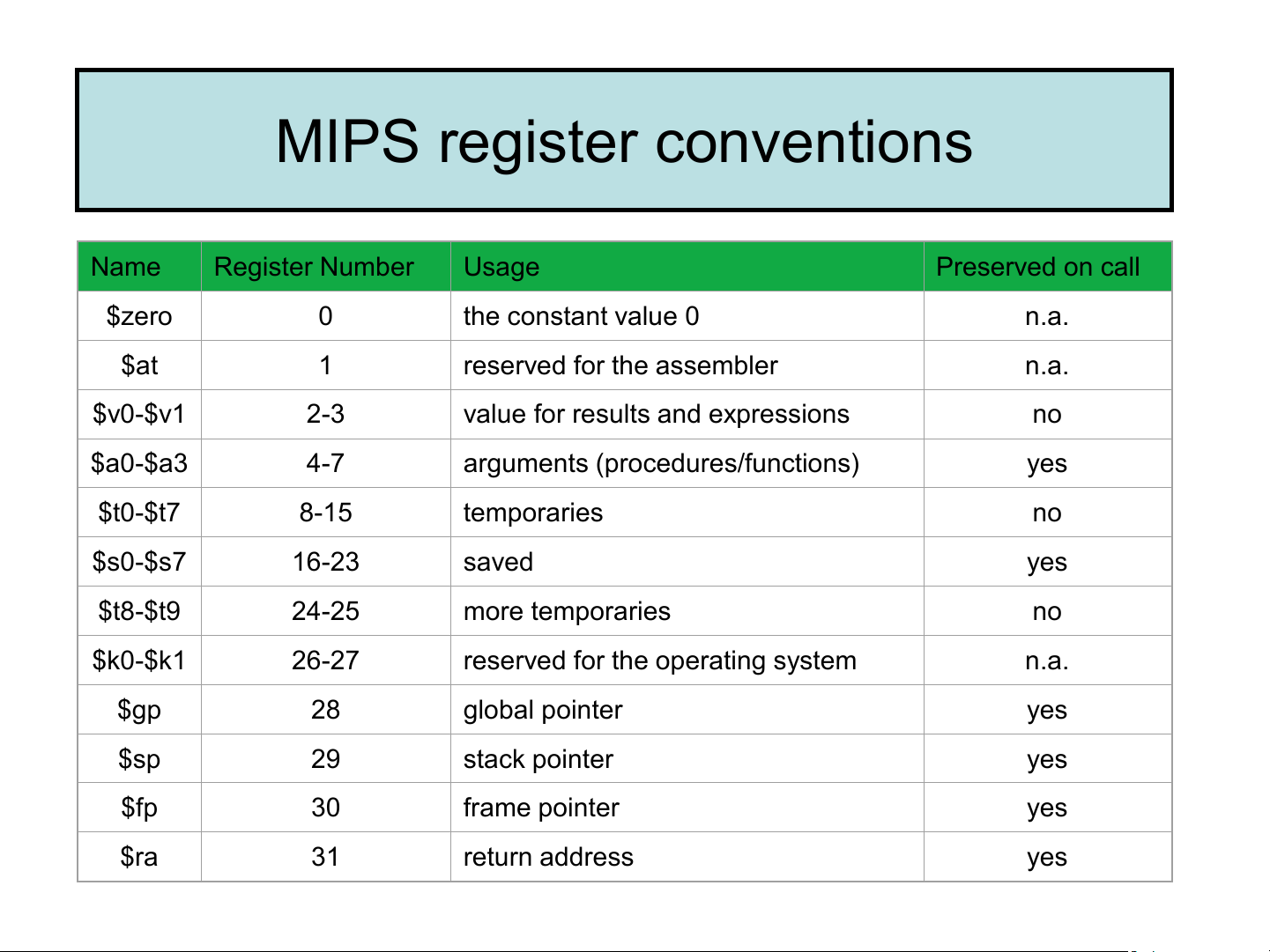
➢ Each register is referred to by a number/name (MIPS example next slide) Address Data 0 int A, B, C; store 4 B C = A + B; 8 C load 12 A 16 R0 ← Mem[12] Up to 232 bytes . . . . R1 organized as 230 ← Mem[4] . . 4-byte words → R2 ← R0 * R1 addresses of 32-bit words consecutive words Mem[8] ← R2 differ by 4. Memory MIPS register conventions Name Register Number Usage Preserved on call $zero 0 the constant value 0 n.a. $at 1 reserved for the assembler n.a. $v0-$v1 2-3
value for results and expressions no $a0-$a3 4-7
arguments (procedures/functions) yes $t0-$t7 8-15 temporaries no $s0-$s7 16-23 saved yes $t8-$t9 24-25 more temporaries no $k0-$k1 26-27
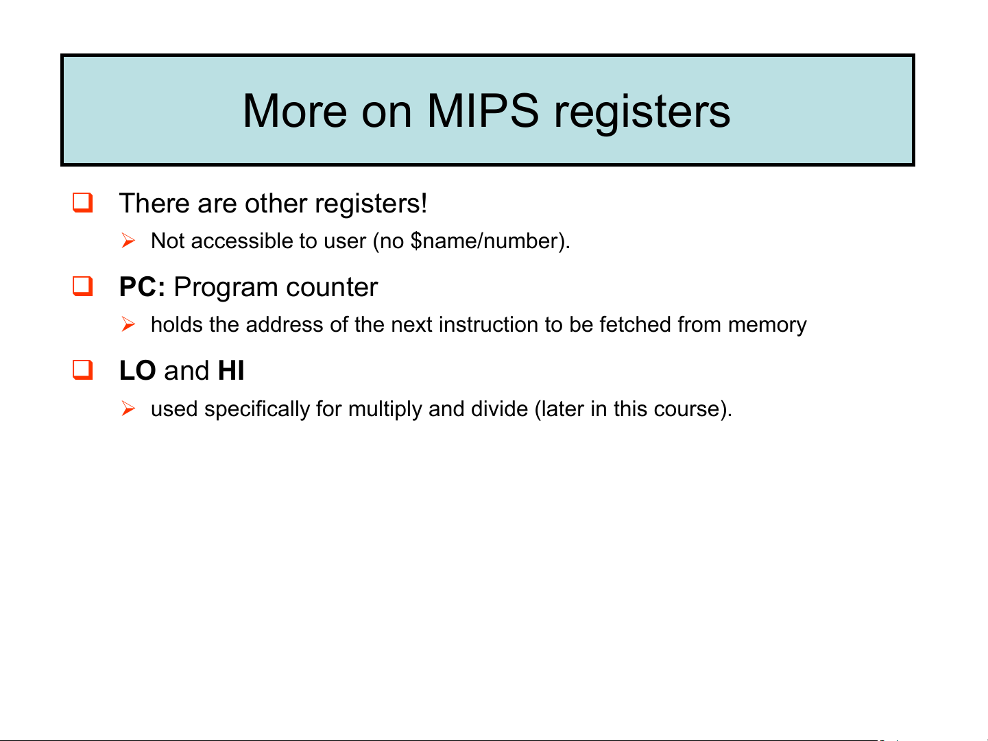
reserved for the operating system n.a. $gp 28 global pointer yes $sp 29 stack pointer yes $fp 30 frame pointer yes $ra 31 return address yes More on MIPS registers ❑ There are other registers!
➢ Not accessible to user (no $name/number).
❑ PC: Program counter
➢ holds the address of the next instruction to be fetched from memory ❑ LO and HI
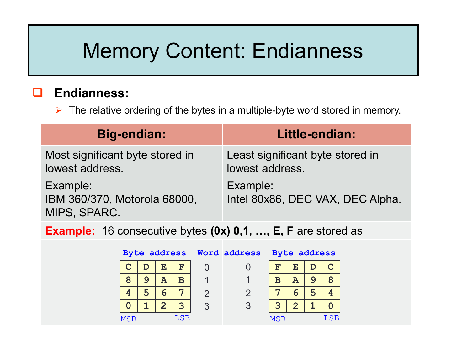
➢ used specifically for multiply and divide (later in this course). Memory Content: Endianness ❑ Endianness:
➢ The relative ordering of the bytes in a multiple-byte word stored in memory. Big-endian: Little-endian:
Most significant byte stored in
Least significant byte stored in lowest address. lowest address. Example: Example: IBM 360/370, Motorola 68000,
Intel 80x86, DEC VAX, DEC Alpha. MIPS, SPARC.
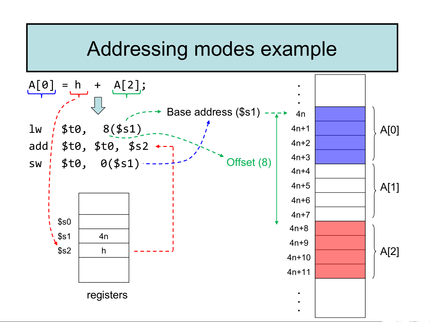
Example: 16 consecutive bytes (0x) 0,1, …, E, F are stored as Byte address Word address Byte address C D E F 0 0 F E D C 8 9 A B 1 1 B A 9 8 4 5 6 7 2 2 7 6 5 4 0 1 2 3 3 3 3 2 1 0 MSB LSB MSB LSB Addressing Modes Addressing mode Example Meaning Register Add R4,R3 R4 R4+R3 MIPS uses only Immediate Add R4,#3 R4 R4+3 the first 3 modes Displacement Add R4,100(R1) R4 R4+Mem[100+R1] Register indirect Add R4,(R1) R4 R4+Mem[R1] Indexed / Base Add R3,(R1+R2) R3 R3+Mem[R1+R2] Direct or absolute Add R1,(1001) R1 R1+Mem[1001] Memory indirect Add R1,@(R3) R1 R1+Mem[Mem[R3]] Auto-increment Add R1,(R2)+ R1 R1+Mem[R2]; R2 R2+d Auto-decrement Add R1,–(R2) R2 R2-d; R1 R1+Mem[R2] Scaled Add R1,100(R2)[R3] R1 R1+Mem[100+R2+R3*d] ❑ Addressing Modes:
➢ Ways to obtain an operand of an instruction. Addressing modes example A[0] = h + A[2]; . . . Base address ($s1) 4n lw $t0, 8($s1) 4n+1 A[0] add $t0, $t0, 4n+2 $s2 4n+3 sw $t0, 0($s1) Offset (8) 4n+4 4n+5 A[1] 4n+6 4n+7 $s0 4n+8 $s1 4n 4n+9 $s2 h A[2] 4n+10 4n+11 . registers . .
Tài liệu liên quan:
-
TỔNG HỢP ĐỀ THI KTMT
24 12 -
Đề thi Kiến trúc máy tính đề số 2 năm học 2020-2021 | Trường Đại học Công nghệ, Đại học Quốc gia Hà Nội
213 107 -
Đề thi và đáp án Kiến trúc máy tính giữa kỳ 1 năm học 2021-2022 | Trường Đại học Công nghệ, Đại học Quốc gia Hà Nội
220 110 -

Đề thi Kiến trúc máy tính CLC giữa kỳ 1 năm học 2022-2023 | Trường Đại học Công nghệ, Đại học Quốc gia Hà Nội
179 90 -
Đề thi Kiến trúc máy tính CLC lần 2 giữa kỳ 1 năm học 2022-2023 | Trường Đại học Công nghệ, Đại học Quốc gia Hà Nội
138 69