SLIDE Week 9 – Lecture 9 – Pipelined Processor Design Kiến Trúc Máy Tính | Trường Đại học Công nghệ, Đại học Quốc gia Hà Nội
SLIDE Week 9 – Lecture 9 – Pipelined Processor Design Kiến Trúc Máy Tính | Trường Đại học Công nghệ, Đại học Quốc gia Hà Nội . Tài liệu được sưu tầm và biên soạn dưới dạng PDF gồm 33 trang giúp bạn tham khảo, củng cố kiến thức và ôn tập đạt kết quả cao trong kỳ thi sắp tới. Mời bạn đọc đón xem!
Môn: Kiến Trúc Máy Tính (UET) 19 tài liệu
Trường: Trường Đại học Công nghệ, Đại học Quốc gia Hà Nội 762 tài liệu
Tác giả:
Preview text:
ELT3047 Computer Architecture
Lecture 9: Pipelined Processor Design Hoang Gia Hung
Faculty of Electronics and Telecommunications
University of Engineering and Technology, VNU Hanoi Last lecture review
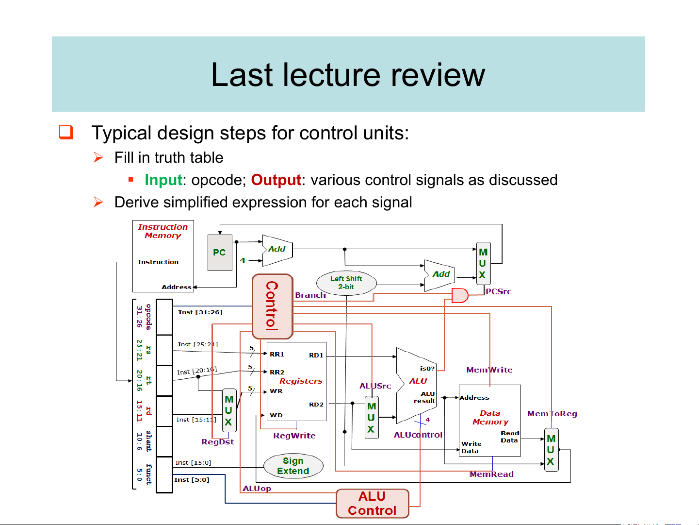
❑ Typical design steps for control units: ➢ Fill in truth table
▪ Input: opcode; Output: various control signals as discussed
➢ Derive simplified expression for each signal
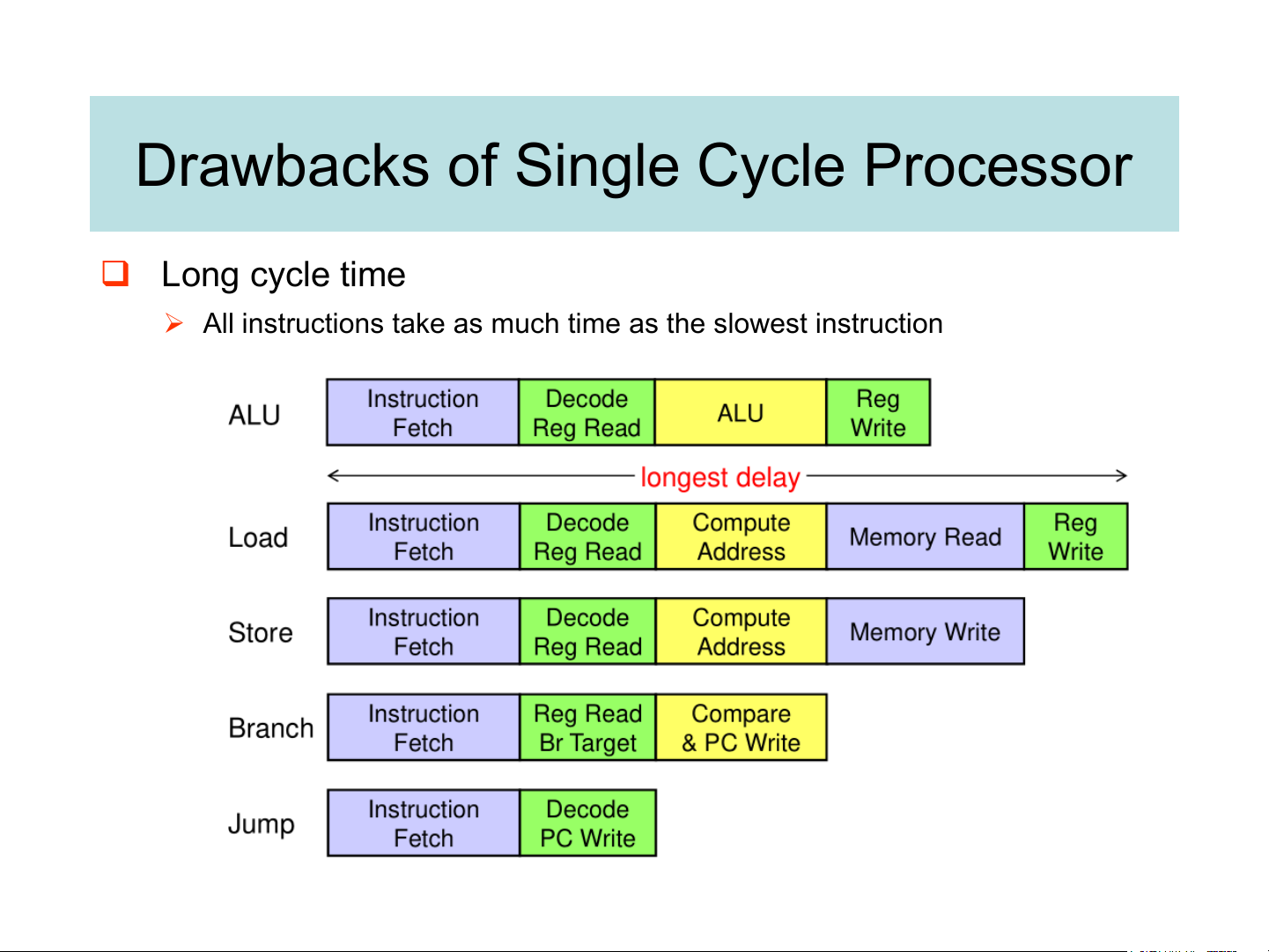
Drawbacks of Single Cycle Processor ❑ Long cycle time
➢ All instructions take as much time as the slowest instruction Worst Case Timing
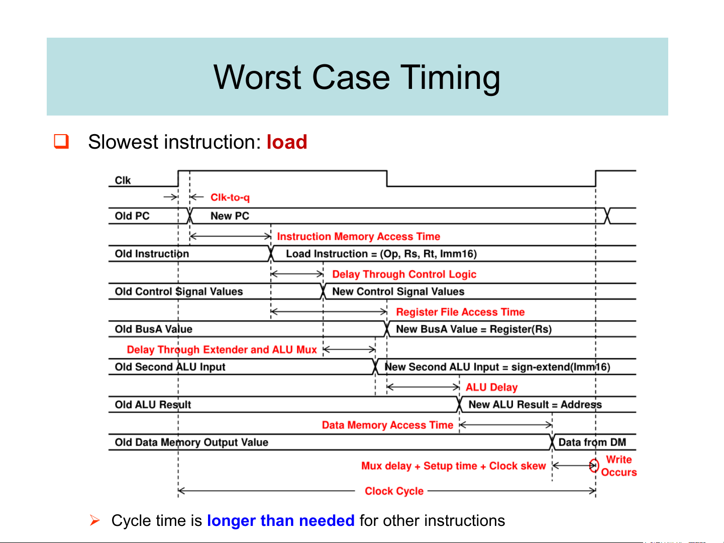
❑ Slowest instruction: load
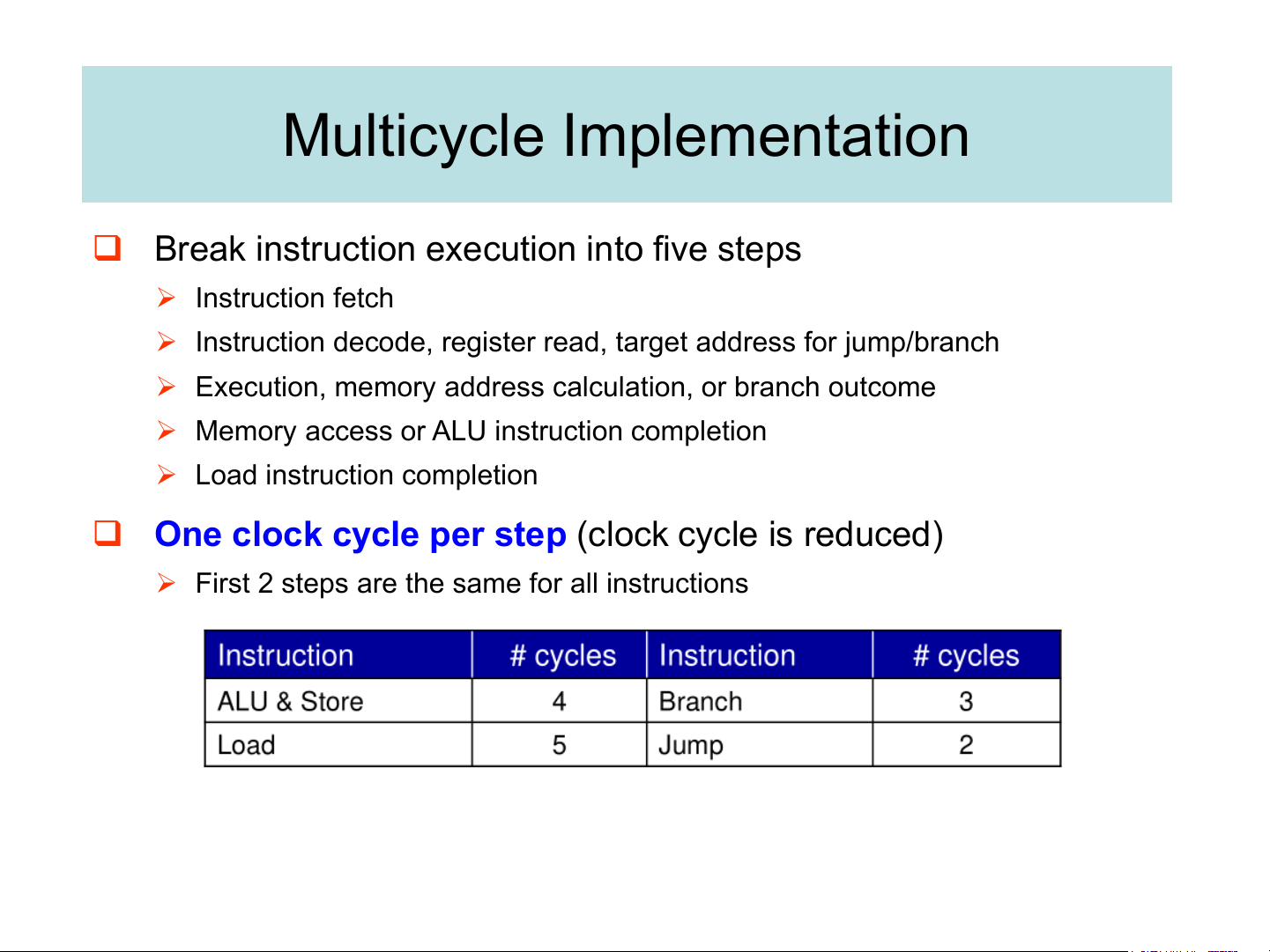
➢ Cycle time is longer than needed for other instructions Multicycle Implementation
❑ Break instruction execution into five steps ➢ Instruction fetch
➢ Instruction decode, register read, target address for jump/branch
➢ Execution, memory address calculation, or branch outcome
➢ Memory access or ALU instruction completion
➢ Load instruction completion
❑ One clock cycle per step (clock cycle is reduced)
➢ First 2 steps are the same for all instructions
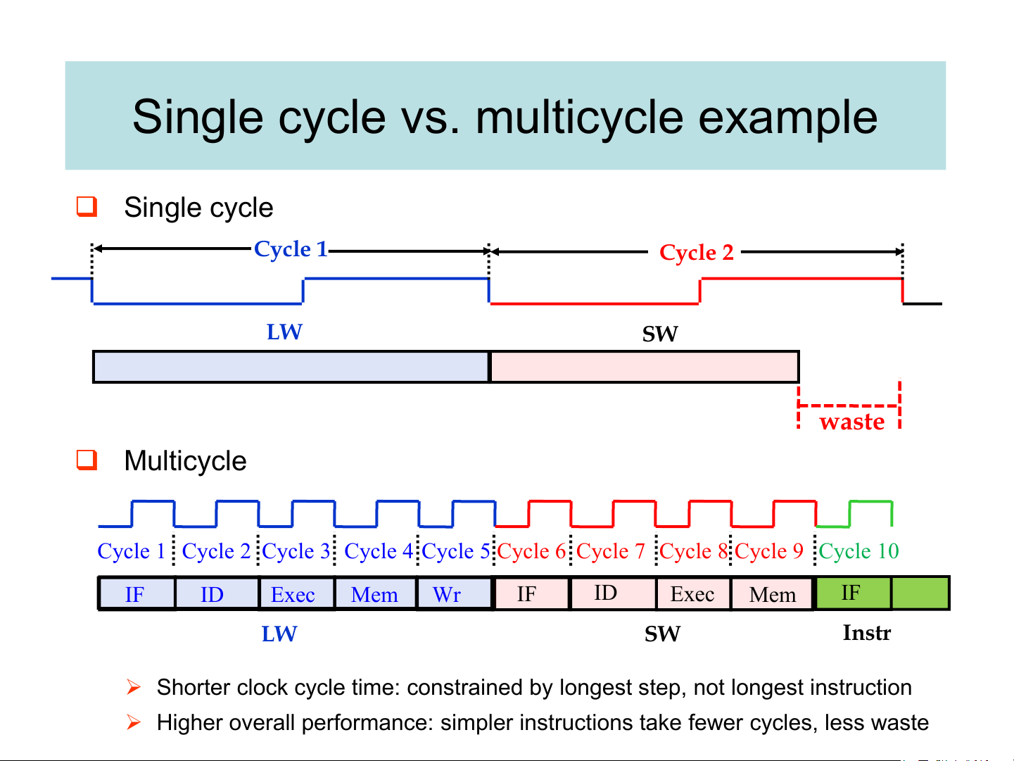
Single cycle vs. multicycle example ❑ Single cycle Cycle 1 Cycle 2 LW SW waste ❑ Multicycle
Cycle 1 Cycle 2 Cycle 3 Cycle 4 Cycle 5 Cycle 6 Cycle 7 Cycle 8 Cycle 9 Cycle 10 IF ID Exec Mem Wr IF ID Exec Mem IF LW SW Instr
➢ Shorter clock cycle time: constrained by longest step, not longest instruction
➢ Higher overall performance: simpler instructions take fewer cycles, less waste Single cycle vs. Multicycle
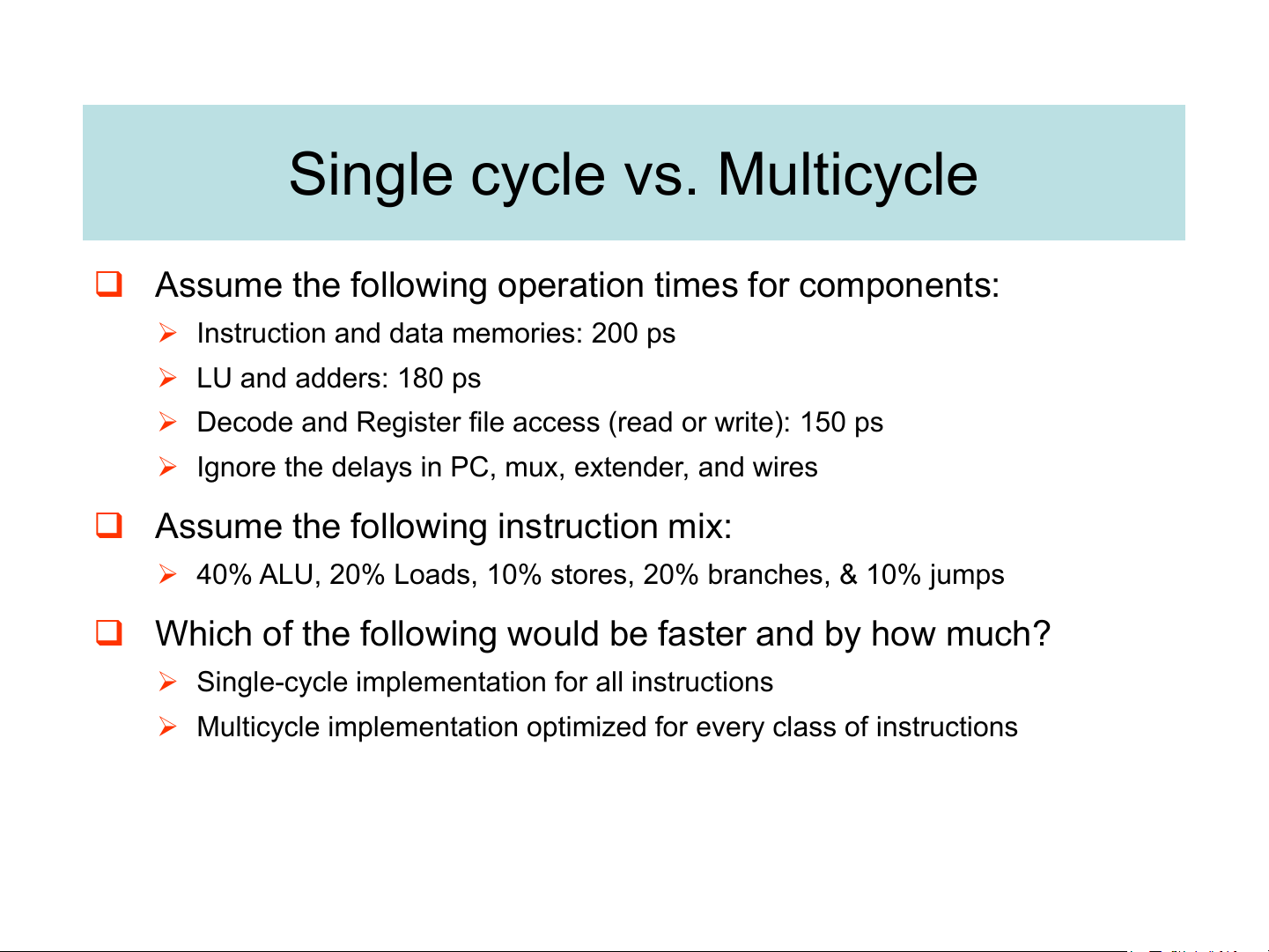
❑ Assume the following operation times for components:
➢ Instruction and data memories: 200 ps ➢ LU and adders: 180 ps
➢ Decode and Register file access (read or write): 150 ps
➢ Ignore the delays in PC, mux, extender, and wires
❑ Assume the following instruction mix:
➢ 40% ALU, 20% Loads, 10% stores, 20% branches, & 10% jumps
❑ Which of the following would be faster and by how much?
➢ Single-cycle implementation for all instructions
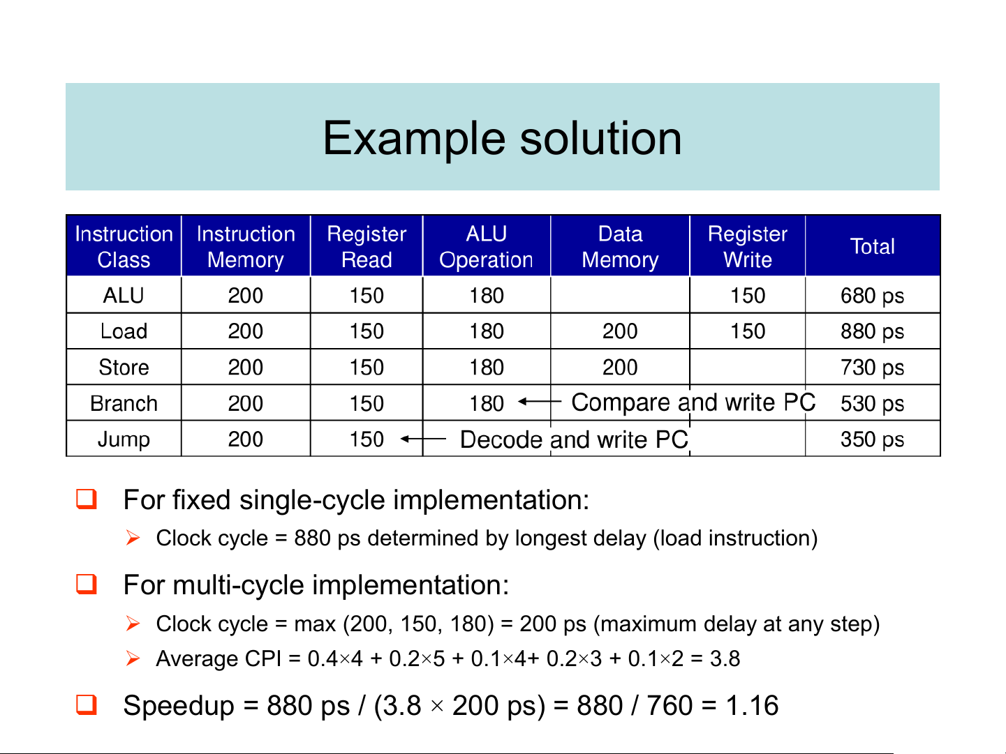
➢ Multicycle implementation optimized for every class of instructions Example solution
❑ For fixed single-cycle implementation:
➢ Clock cycle = 880 ps determined by longest delay (load instruction)
❑ For multi-cycle implementation:
➢ Clock cycle = max (200, 150, 180) = 200 ps (maximum delay at any step)
➢ Average CPI = 0.4×4 + 0.2×5 + 0.1×4+ 0.2×3 + 0.1×2 = 3.8
❑ Speedup = 880 ps / (3.8 × 200 ps) = 880 / 760 = 1.16 The idea of pipelining
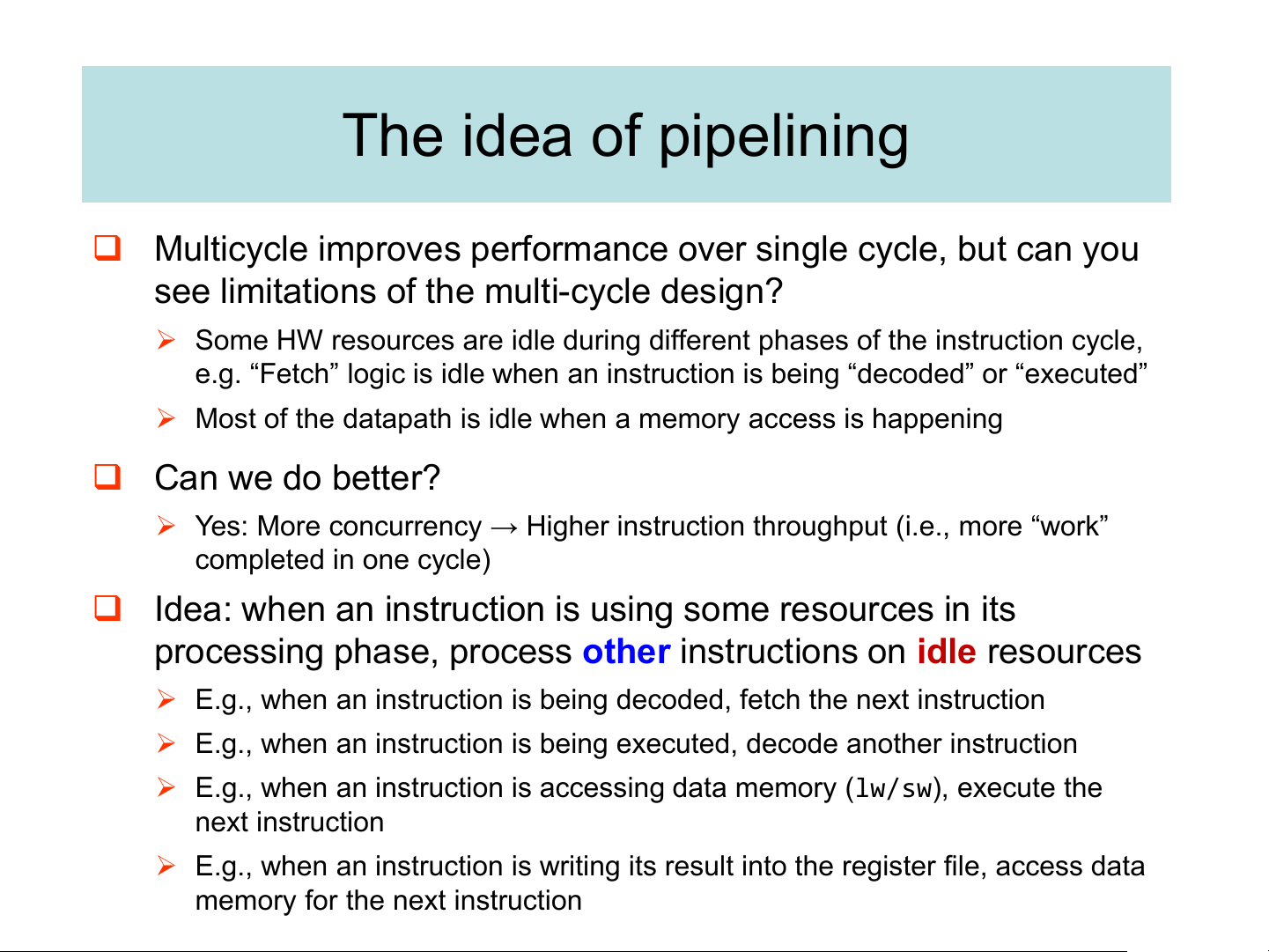
❑ Multicycle improves performance over single cycle, but can you
see limitations of the multi-cycle design?
➢ Some HW resources are idle during different phases of the instruction cycle,
e.g. “Fetch” logic is idle when an instruction is being “decoded” or “executed”
➢ Most of the datapath is idle when a memory access is happening ❑ Can we do better?
➢ Yes: More concurrency → Higher instruction throughput (i.e., more “work” completed in one cycle)
❑ Idea: when an instruction is using some resources in its
processing phase, process other instructions on idle resources
➢ E.g., when an instruction is being decoded, fetch the next instruction
➢ E.g., when an instruction is being executed, decode another instruction
➢ E.g., when an instruction is accessing data memory (lw/sw), execute the next instruction
➢ E.g., when an instruction is writing its result into the register file, access data
memory for the next instruction A laundry analogy
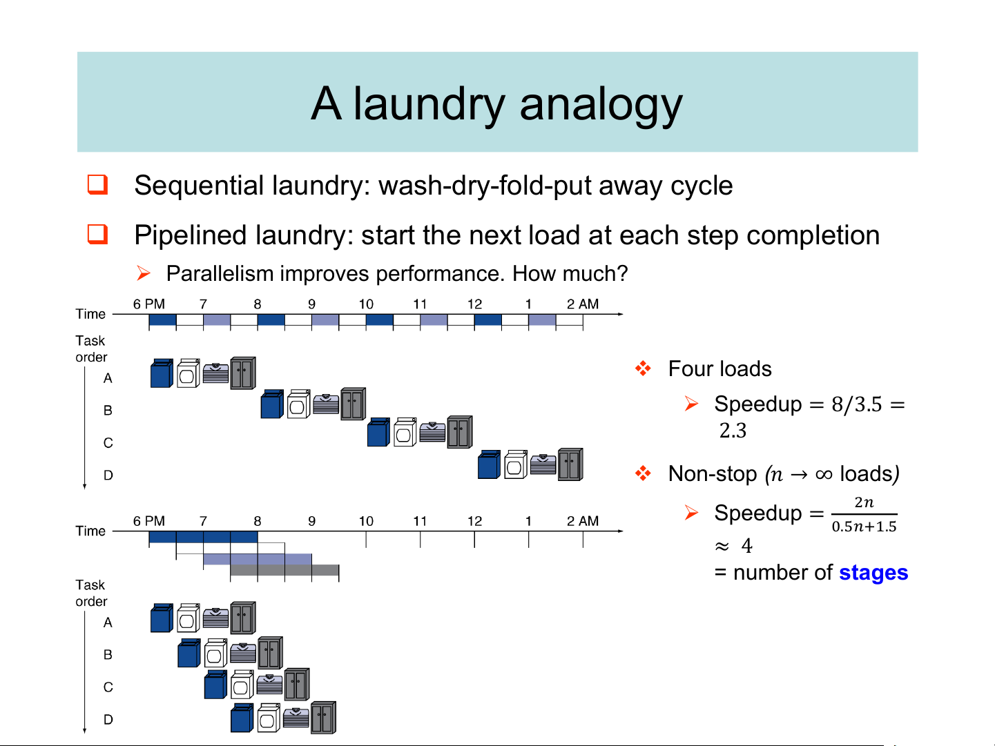
❑ Sequential laundry: wash-dry-fold-put away cycle
❑ Pipelined laundry: start the next load at each step completion
➢ Parallelism improves performance. How much? ❖ Four loads ➢ Speedup = 8/3.5 = 2.3
❖ Non-stop (𝑛 → ∞ loads) ➢ Speedup = 2𝑛 0.5𝑛+1.5 ≈ 4 = number of stages
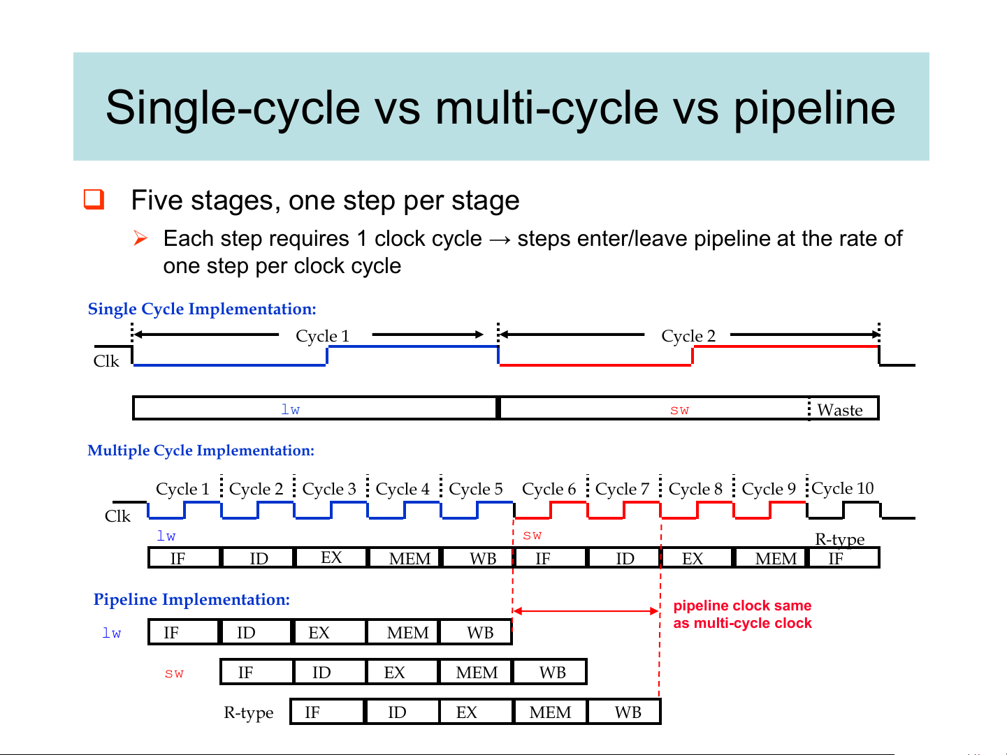
Single-cycle vs multi-cycle vs pipeline
❑ Five stages, one step per stage
➢ Each step requires 1 clock cycle → steps enter/leave pipeline at the rate of one step per clock cycle
Single Cycle Implementation: Cycle 1 Cycle 2 Clk lw sw Waste
Multiple Cycle Implementation: Cycle 1 Cycle 2 Cycle 3 Cycle 4 Cycle 5 Cycle 6 Cycle 7 Cycle 8 Cycle 9 Cycle 10 Clk lw sw R-type IF ID EX MEM WB IF ID EX MEM IF
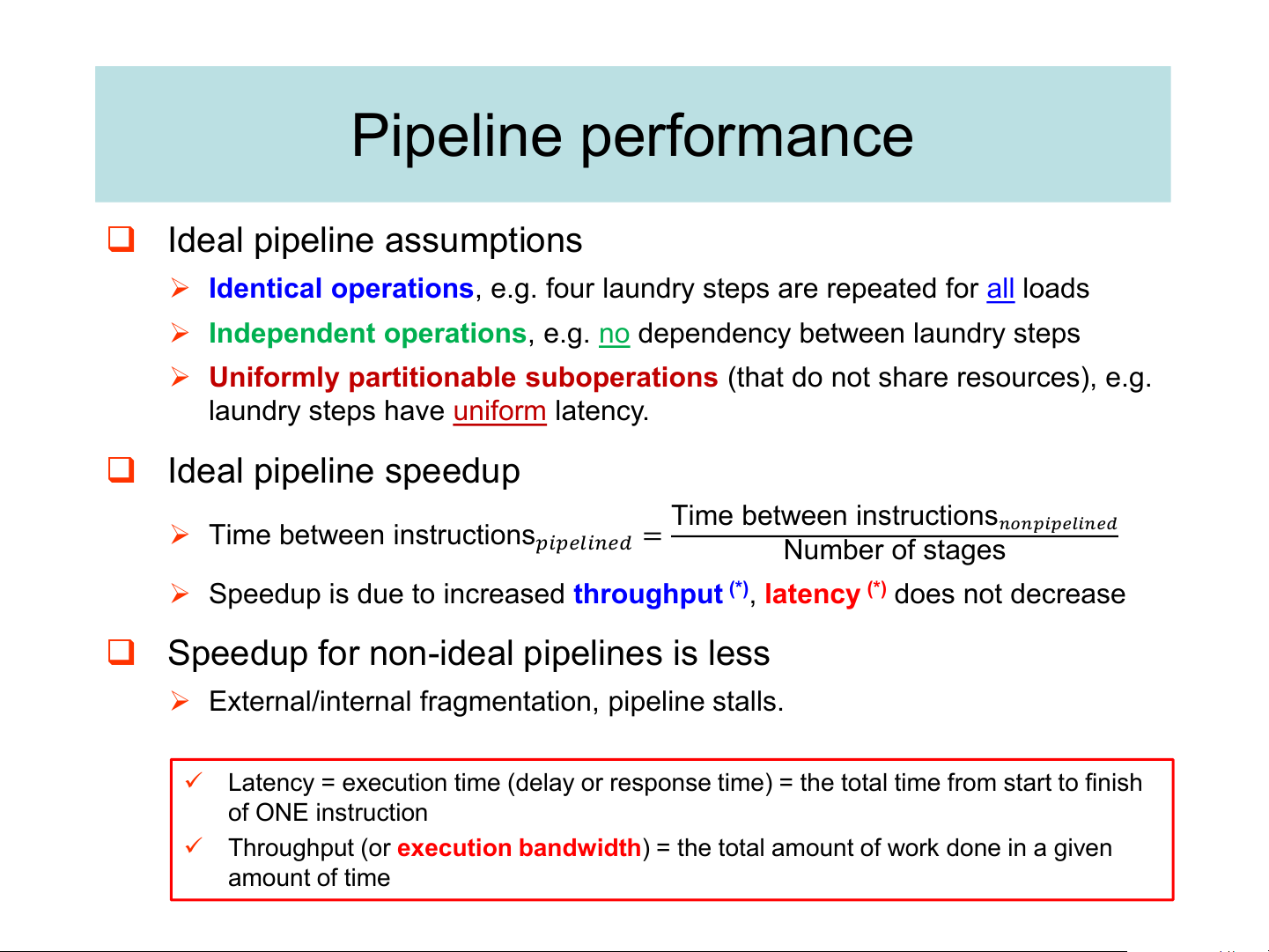
Pipeline Implementation: pipeline clock same as multi-cycle clock lw IF ID EX MEM WB sw IF ID EX MEM WB R-type IF ID EX MEM WB Pipeline performance ❑ Ideal pipeline assumptions
➢ Identical operations, e.g. four laundry steps are repeated for all loads
➢ Independent operations, e.g. no dependency between laundry steps
➢ Uniformly partitionable suboperations (that do not share resources), e.g.
laundry steps have uniform latency. ❑ Ideal pipeline speedup Time between instructions ➢ Time between instructions
𝑛𝑜𝑛𝑝𝑖𝑝𝑒𝑙𝑖𝑛𝑒𝑑
𝑝𝑖𝑝𝑒𝑙𝑖𝑛𝑒𝑑 = Number of stages
➢ Speedup is due to increased throughput (*), latency (*) does not decrease
❑ Speedup for non-ideal pipelines is less
➢ External/internal fragmentation, pipeline stalls.
✓ Latency = execution time (delay or response time) = the total time from start to finish of ONE instruction
✓ Throughput (or execution bandwidth) = the total amount of work done in a given amount of time
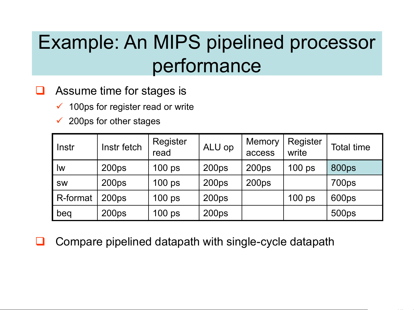
Example: An MIPS pipelined processor performance ❑ Assume time for stages is
✓ 100ps for register read or write ✓ 200ps for other stages Register Memory Register Instr Instr fetch ALU op Total time read access write lw 200ps 100 ps 200ps 200ps 100 ps 800ps sw 200ps 100 ps 200ps 200ps 700ps R-format 200ps 100 ps 200ps 100 ps 600ps beq 200ps 100 ps 200ps 500ps
❑ Compare pipelined datapath with single-cycle datapath
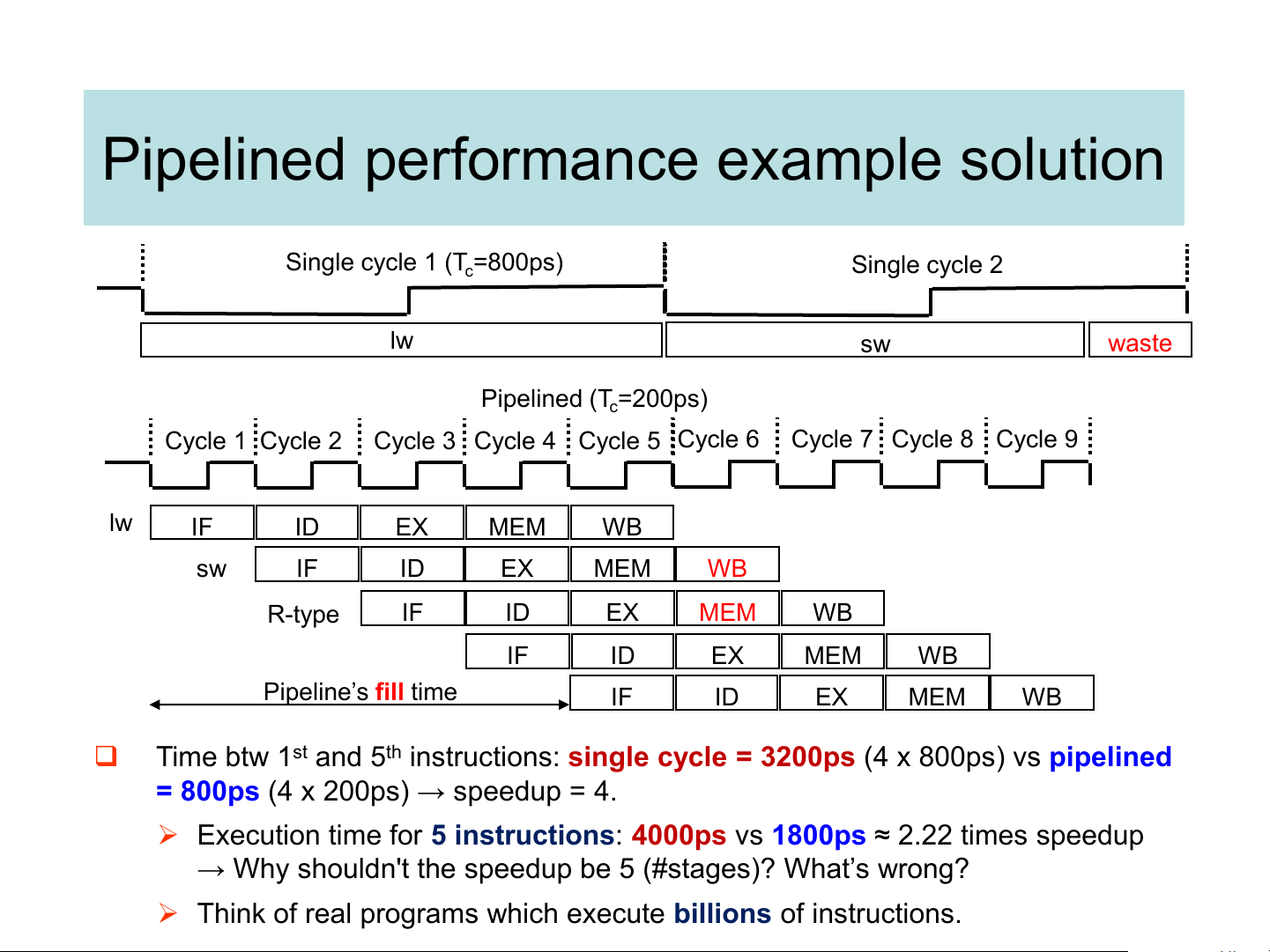
Pipelined performance example solution Single cycle 1 (T =800ps) c Single cycle 2 lw sw waste Pipelined (T =200ps) c Cycle 1 Cycle 2
Cycle 3 Cycle 4 Cycle 5 Cycle 6 Cycle 7 Cycle 8 Cycle 9 lw IF ID EX MEM WB sw IF ID EX MEM WB R-type IF ID EX MEM WB IF ID EX MEM WB Pipeline’s fill time IF ID EX MEM WB ❑
Time btw 1st and 5th instructions: single cycle = 3200ps (4 x 800ps) vs pipelined
= 800ps (4 x 200ps) → speedup = 4.
➢ Execution time for 5 instructions: 4000ps vs 1800ps ≈ 2.22 times speedup
→ Why shouldn't the speedup be 5 (#stages)? What’s wrong?
➢ Think of real programs which execute billions of instructions.
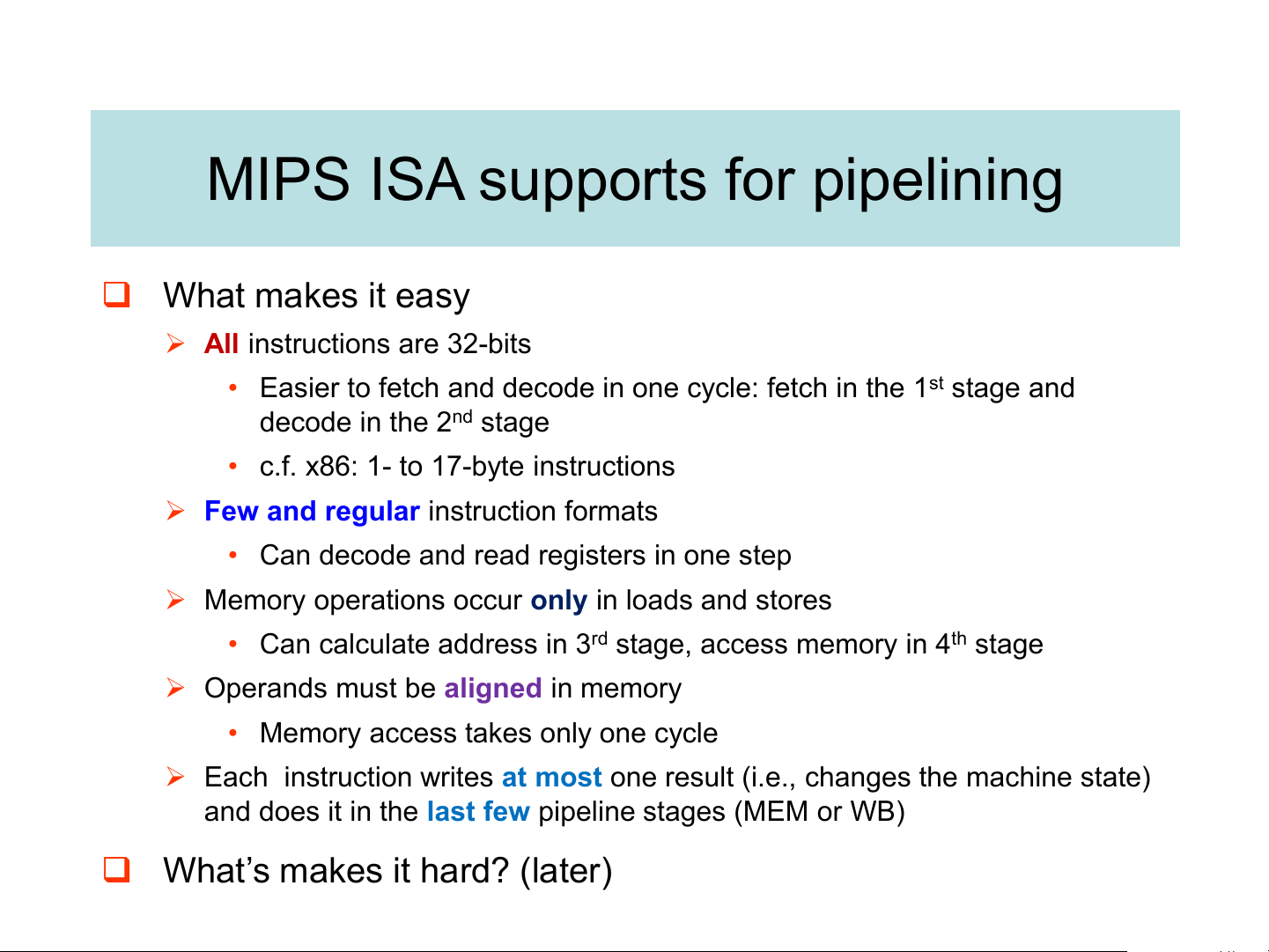
MIPS ISA supports for pipelining ❑ What makes it easy
➢ All instructions are 32-bits
• Easier to fetch and decode in one cycle: fetch in the 1st stage and decode in the 2nd stage
• c.f. x86: 1- to 17-byte instructions
➢ Few and regular instruction formats
• Can decode and read registers in one step
➢ Memory operations occur only in loads and stores
• Can calculate address in 3rd stage, access memory in 4th stage
➢ Operands must be aligned in memory
• Memory access takes only one cycle
➢ Each instruction writes at most one result (i.e., changes the machine state)
and does it in the last few pipeline stages (MEM or WB)
❑ What’s makes it hard? (later)
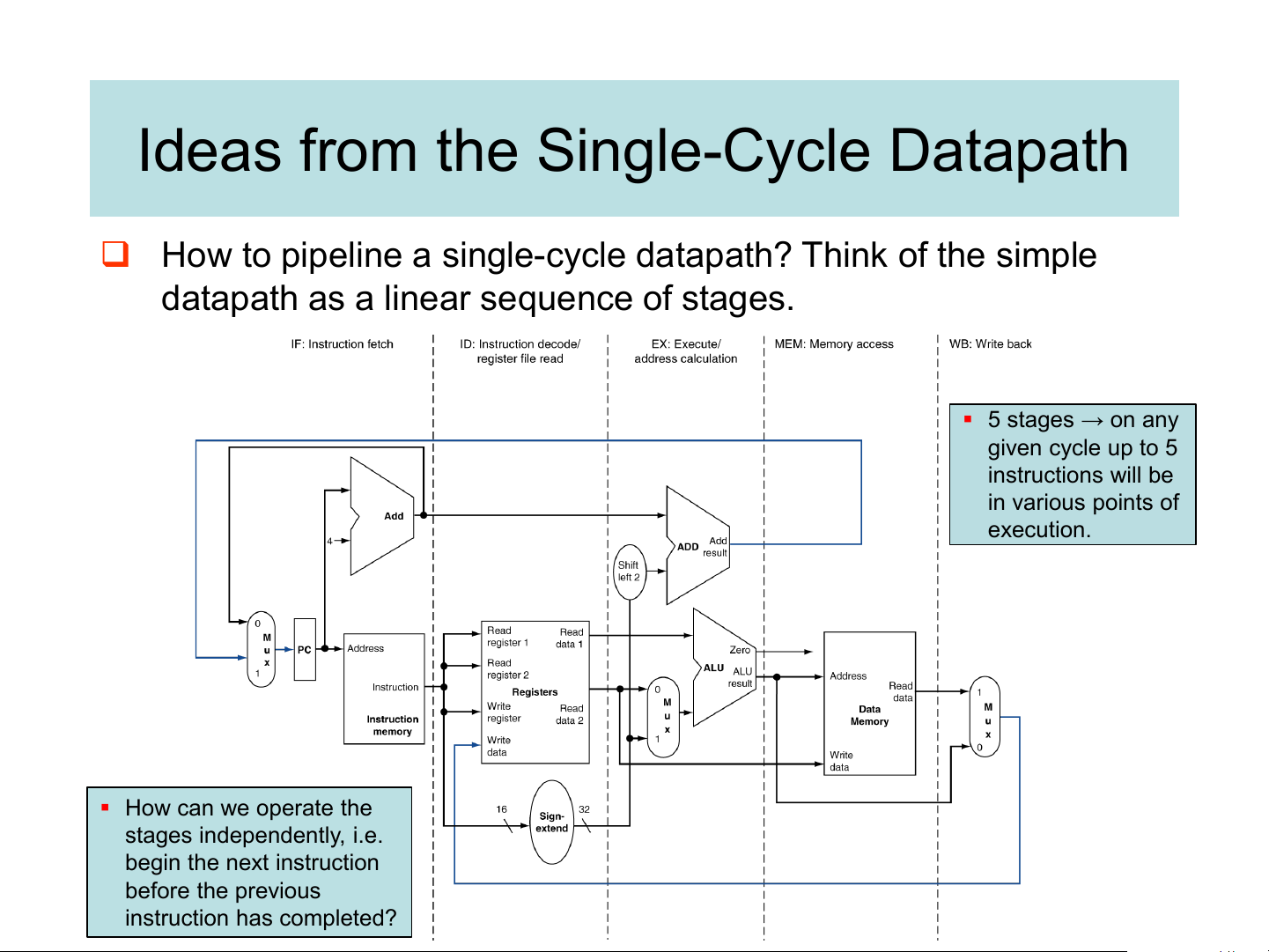
Ideas from the Single-Cycle Datapath
❑ How to pipeline a single-cycle datapath? Think of the simple
datapath as a linear sequence of stages. ▪ 5 stages → on any given cycle up to 5 instructions will be in various points of execution. ▪ How can we operate the stages independently, i.e. begin the next instruction before the previous instruction has completed? Pipelined Datapath
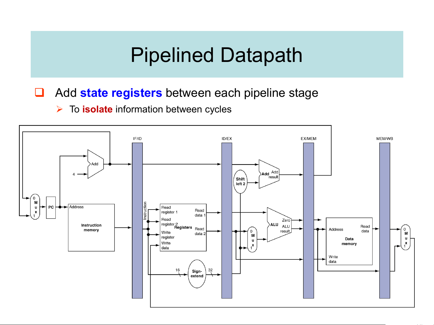
❑ Add state registers between each pipeline stage
➢ To isolate information between cycles Pipeline operation
❑ Cycle-by-cycle flow of instructions through the pipelined datapath
➢ Same clock edge updates all pipeline registers, register file, and data memory (for store instruction)
➢ “Single-clock-cycle” pipeline diagram
✓ Shows pipeline usage in a single cycle ✓ Highlight resources used
➢ c.f. “multi-clock-cycle” diagram (later)
✓ Graph of operation over time
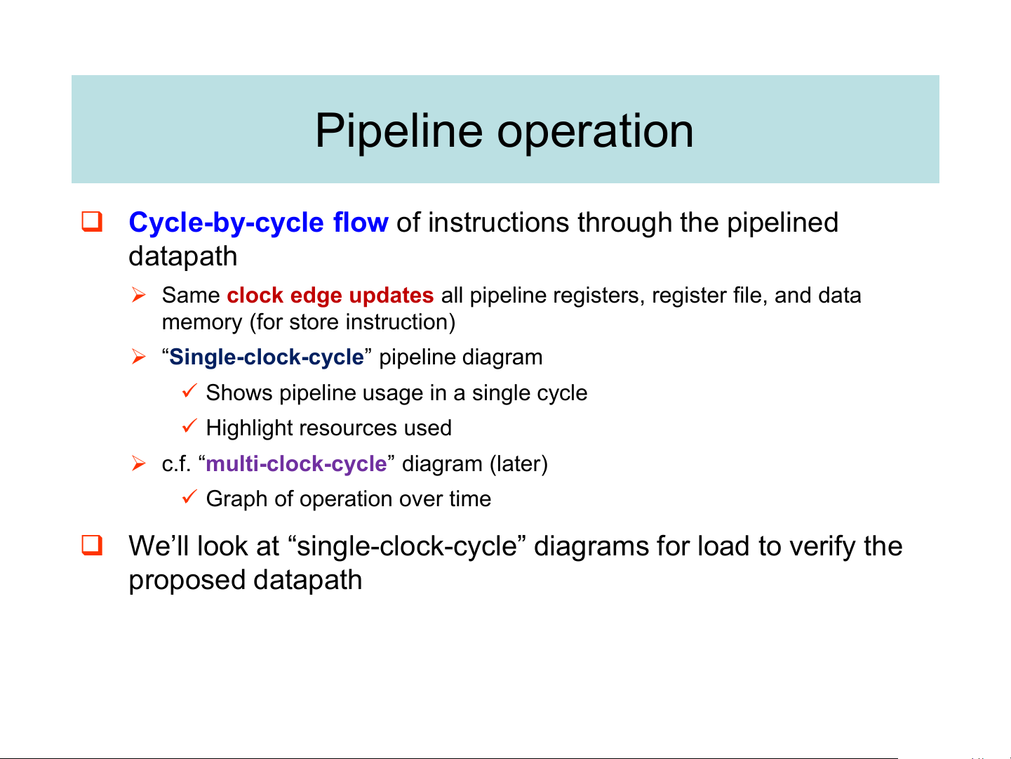
❑ We’ll look at “single-clock-cycle” diagrams for load to verify the proposed datapath IF for Load, Store, … PC+4 is computed, stored back into the PC, stored in the IF/ID buffer although it
will not be needed in a later stage for LW
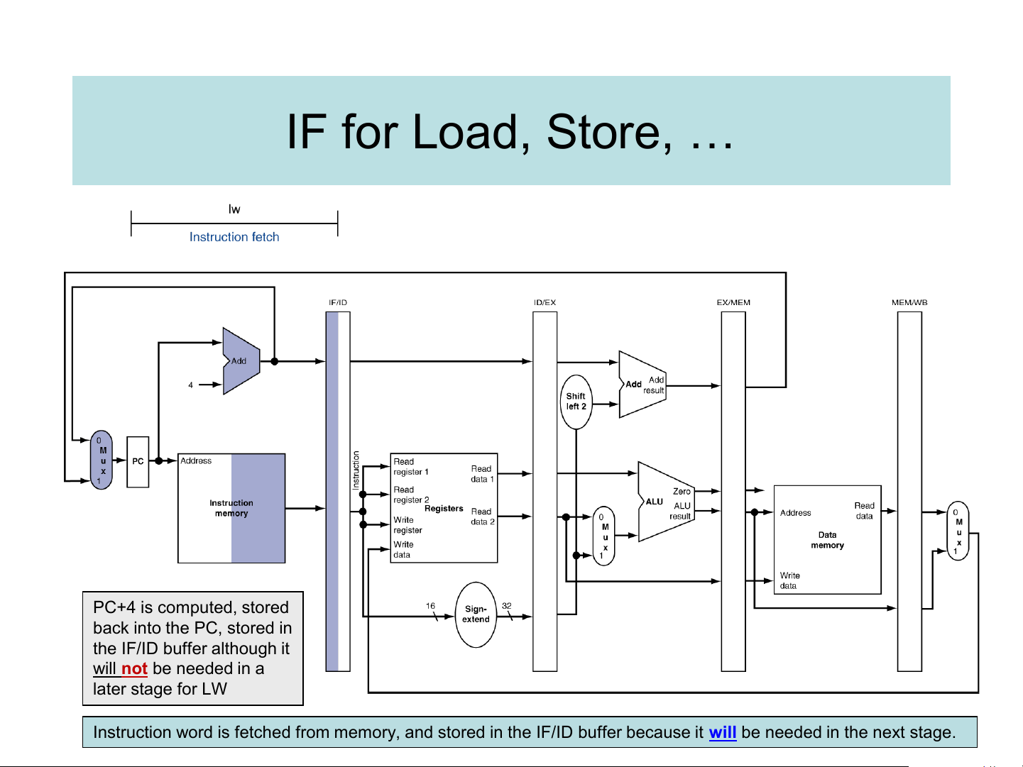
Instruction word is fetched from memory, and stored in the IF/ID buffer because it will be needed in the next stage. ID for Load, Store, … PC+4 is passed forward to ID/EX buffer RR #1 & #2 contents are fetched & stored in ID/EX buffer Bits of load instruction are
taken from IF/ID buffer, while
new instruction is being fetched
16-bit field is fetched from IF/ID buffer, then
sign-extended, then stored in the ID/EX buffer for use in a later stage.
Tài liệu liên quan:
-
TỔNG HỢP ĐỀ THI KTMT
24 12 -
Đề thi Kiến trúc máy tính đề số 2 năm học 2020-2021 | Trường Đại học Công nghệ, Đại học Quốc gia Hà Nội
213 107 -
Đề thi và đáp án Kiến trúc máy tính giữa kỳ 1 năm học 2021-2022 | Trường Đại học Công nghệ, Đại học Quốc gia Hà Nội
220 110 -

Đề thi Kiến trúc máy tính CLC giữa kỳ 1 năm học 2022-2023 | Trường Đại học Công nghệ, Đại học Quốc gia Hà Nội
179 90 -
Đề thi Kiến trúc máy tính CLC lần 2 giữa kỳ 1 năm học 2022-2023 | Trường Đại học Công nghệ, Đại học Quốc gia Hà Nội
138 69