Term paper on steel structures | Môn Cơ học kết cấu - Đại học Cần Thơ
The design of the load-bearing horizontal frame of a single-storey, single-span industrial building (Yamil steel frame factory) factory has 17 column steps. Tài liệu được sưu tầm gồm 120 trang, giúp bạn ôn tập tốt hơn. Mời các bạn đón xem.
Môn: Cơ học kết cấu (CN154) 10 tài liệu
Trường: Trường Đại học Cần Thơ 813 tài liệu
Tác giả:


Preview text:
Table of Contents
TERM PAPER OF STEEL STRUCTURES......................................................................................................1
CHATER I. DETERMINE THE MAIN DIMENSIONS OF THE HORIZONTAL FRAME......................................2
I. Vertical dimensions.............................................................................................................................2 II. Horizontal
size....................................................................................................................................3III. Preliminary
selection of cross section:...............................................................................................3 1.
Preliminary selection of column size and cross-
section:.....................................................................3 2. Select the cross section of
bar:...........................................................................................................4 3.
Preliminarily choose the size and cross-section of the
skylight:.........................................................5 CHAPTER II. DESIGN OF BRACING
SYSTEM.............................................................................................7
I. ROOF BRACING SYSTEM AND POST BRACING SYSTEM........................................................................7 1. Roof bracing
system...........................................................................................................................7 2. Post braceing
system..........................................................................................................................7II. ROOF DOOR
BRACING SYSTEM...........................................................................................................8
1. Bracing the upper wings.....................................................................................................................8 2. Vertical
bracing...................................................................................................................................8CHAPTER
III. DESIGN OF TOLE ROOFING................................................................................................9 I.
CHARACTERISTICS OF GEOMETRIC SECTIONS:.....................................................................................9
II. CALCULATION DIAGRAM:...................................................................................................................9
III. LOAD ON TOLE SHEETS:.....................................................................................................................9 1. Wind
load:..........................................................................................................................................9 2. Roof live
load:...................................................................................................................................10 3. Weight of the tole
sheet:..................................................................................................................11 4.
Combination of loads acting on the tole
sheet:................................................................................11 5.
Internal force and cross section check of corrugated iron
sheet:.....................................................11 CHAPTER IV. DESIGN OF ROOFING PURLIN
SYSTEM............................................................................13
I. DESIGN OF ROOFING PURLIN:...........................................................................................................13
II. ROOF PURLIN CALCULATION:...........................................................................................................13
1. Preliminary selection of purlins:.......................................................................................................13
2. Load on purlins:................................................................................................................................13
3. Internal force in the purlin:...............................................................................................................154.
Check purlin cross section:...............................................................................................................15
CHAPTER V. DESIGN OF WALL PURLIN
SYSTEM....................................................................................17
I. PRELIMINARY SELECTION OF THE WALL PURLIN SECTION................................................................17 II.
LOAD ON THE WALL PURLIN:............................................................................................................17
1. Vertical direction: (along the x-x axis)...............................................................................................17
2. Horizontal direction: (along the y-y axis)..........................................................................................18
III. CALCULATION:.................................................................................................................................18 IV. CHECK THE WALL PURLIN
SECTION:................................................................................................18CHAPTER VI. THE LOAD ON
THE MAIN FRAME....................................................................................20 I. DEAD
LOAD:.......................................................................................................................................20
II. ROOF LIVE LOAD:..............................................................................................................................21
III. WIND LOAD:....................................................................................................................................23
1. Wind load on the column:................................................................................................................24
2. Wind load on the roof:.....................................................................................................................24
3. Wind load on the skyline column:....................................................................................................24
4. The wind load on the roof of the skyroof:........................................................................................25
IV. CRANE LIVE LOAD:...........................................................................................................................26
CHAPTER VII. DETERMINATION OF INTERNAL FORCES AND COMBINATIONS OF INTERNAL FORCES..30
I. Loading cases:....................................................................................................................................30
II. Load combination:............................................................................................................................30
III. INTERNAL FORCES DIAGRAM:..........................................................................................................33
1. Internal force (DEAD LOAD):.............................................................................................................33
2. Live load filling the roof (HT1):.........................................................................................................34
3. Live load left half-roof (HT2):............................................................................................................36
4. Live load right half-roof (HT3):..........................................................................................................37
5. Vertical pressure of the crane on the left column (HT4):..................................................................39
6. Vertical pressure of the crane on the right column (HT5):...............................................................40
7. The horizontal braking force of the crane on the left column is outward direction (HT6):...............42
8. The horizontal braking force of the crane on the left column is inward direction (HT7):.................43
9. The horizontal braking force of the crane on the right column is outward direction (HT8):............45
10. The horizontal braking force of the crane on the right column is inward direction (HT9):.............46
11. Left wind (GT):................................................................................................................................48
12. Right wind (GP):..............................................................................................................................49
13. BAO Diagram (BAO):.......................................................................................................................51
IV. INTERNAL RESOURCES SUMMARY:.................................................................................................52
CHAPTER VIII. COMPONENT CROSS SECTION DESIGN.........................................................................54
I. COLUMN CROSS SECTION DESIGN.....................................................................................................54
1. Determine the calculated length......................................................................................................54
2. Select and check the cross section with the Mmin – Ntu.....................................................................55
3. Check the selected column cross section with the internal force pair Mmax; Ntứ:
..............................................................................................................................................................60
4. Check the selected column cross-section with internal force pair Nmax; Mtứ:....................................64
5. The largest horizontal displacement at the top of the column from the results of calculations using
SAP 2000 software in a standard combination of static load and left wind load is:..............................68
II. CROSSBAR CROSS SECTION DESIGN:.................................................................................................69 1.
Select and check the cross section of the beam section to change the cross
section:.....................69 2.
Select the cross section and check with the internal force pair: Mmax -
Ntư.......................................72 3.
Select the cross section and check with the internal force pair: Nmax -
Mtư.......................................73 4.
Select and check the beam segment cross section does not change the cross section:...................75 5.
Select the cross section and check with the internal force pair: Mmin -
Ntư.......................................78 6.
Select the cross section and check with the internal force pair: Nmax -
Mtư.......................................79 III. SKYGATE CROSS SECTION
DESIGN:..................................................................................................80 1.
Determination of the calculated
length:...........................................................................................80 2.
Select and check the cross section with the Mmin –
Ntu.....................................................................81 IV. KYBEAM CROSS SECTION
DESIGN....................................................................................................86 1. Select the
section:............................................................................................................................86 2. Check cross-
secton:..........................................................................................................................86CHAPTER IX.
DESIGN THE DETAILS.......................................................................................................89
I. THE CRANE BRACKET:........................................................................................................................89
1. Beam cran bracket cross section:.....................................................................................................89
2. Crane bracket cross section:.............................................................................................................90
3. Local stability test of the flange plate and crane bracket web plate:...............................................90
4. Check the weld seams in the weld link:............................................................................................91
5. The dimensions of the pair of reinforcing ribs for the crane bracket web are as follows:................91
II. BOTTOM OF COLUMN:.....................................................................................................................92
1. Base calculation:...............................................................................................................................92
2. Base beam calculation:.....................................................................................................................94
3. Calculation of rib A:..........................................................................................................................94
4. Calculation of rib B:..........................................................................................................................95
5. Calculation of anchor bolts:..............................................................................................................966.
Calculation of line welding that link columns to the base:...............................................................98 III. LINK THE COLUMN TO THE
CROSSBAR:.........................................................................................100
1. Calculation of conecting bolts:........................................................................................................100
2. Flange calculation:..........................................................................................................................103
3. Calculation of the line welding connecting the column cross section (crossbar) to the flange:.....103 IV. JOINT AT HEAD
BEAM:..................................................................................................................104 V. BEAM JOINTS AT
SPAN:..................................................................................................................107 VI.
CONNECTING THE FLANGE WITH THE WEB AND
CROSSBAR:........................................................110VII. CONNECT THE SKYLINE TO THE MAIN
FRAME:.............................................................................110
1. Bonding bolt calculation:................................................................................................................110
2. Flange calculation:..........................................................................................................................113
3. Calculation of the line welding connecting the column cross section (crossbar) to the flange:.....113
VIII. SKYGATE TOP JOINT:...................................................................................................................114 Table of Figure
Figure 1. Preliminarily selected column cross section..................................................................4
Figure 2. Preliminarily selected head of bar section.....................................................................4
Figure 3. Preliminarily selected end of bar section.......................................................................5
Figure 4. Preliminary selection of skylight column cross section..................................................5
Figure 5. Main dimensions of main frames..................................................................................6
Figure 6. Floor plan for roof bracing system.................................................................................7
Figure 7. Installation post bracing system....................................................................................8
Figure 8. The floor plan installation the flange bracing system on the roof door.........................8
Figure 9. Installation the vertical bracing system for the roof door.............................................8
Figure 10. Tole sheet cross section...............................................................................................9
Figure 11. Diagram for determining aerodynamic coefÏcient....................................................10
Figure 12. Purlin cross-section....................................................................................................13
Figure 13. Diagram of distributed load on purlins......................................................................14
Figure 14. Purlin cross-section....................................................................................................17
Figure 15. Framed diagram with frequent loads (Dead load).....................................................21
Figure 16. Left half-roof live load................................................................................................22
Figure 17. Right half-roof live load.............................................................................................22
Figure 18. Loaded roof live load.................................................................................................23
Figure 19. Diagram of the aerodynamic coefÏcient....................................................................24
Figure 20. Left Wind Load...........................................................................................................25
Figure 21. Right Wind Load........................................................................................................25
Figure 22. Lines of influence to determine Dmax, Dmin.............................................................27
Figure 23. The standing pressure of the crane acts on the left column......................................27
Figure 24. The vertical pressure of the crane acts on the right column......................................28
Figure 25. Transverse braking force of the crane on the left column.........................................29
Figure 26. Transverse braking force of the crane on the right column.......................................29
Figure 27. Moment (Tm)............................................................................................................33
Figure 28. Shear force (T)...........................................................................................................33
Figure 29. Axial force (T).............................................................................................................34
Figure 30. Moment (Tm)............................................................................................................34
Figure 31. Shear force (T)...........................................................................................................35
Figure 32. Axial force (T).............................................................................................................35
Figure 33. Moment (Tm)............................................................................................................36
Figure 34. Shear force (T)...........................................................................................................36
Figure 35. Axial force (T).............................................................................................................37
Figure 36. Moment (Tm)............................................................................................................37
Figure 37. Shear force (T)...........................................................................................................38
Figure 38. Axial force (T).............................................................................................................38
Figure 39. Moment (Tm)............................................................................................................39
Figure 40. Shear force (T)...........................................................................................................39
Figure 41. Axial force (T).............................................................................................................40
Figure 42. Moment (Tm)............................................................................................................40
Figure 43. Shear force (T)...........................................................................................................41
Figure 44. Axial force (T).............................................................................................................41
Figure 45. Moment (Tm)............................................................................................................42
Figure 46. Shear force (T)...........................................................................................................42
Figure 47. Axial force (T).............................................................................................................43
Figure 48. Moment (Tm)............................................................................................................43
Figure 49. Shear force (T)...........................................................................................................44
Figure 50. Axial force (T).............................................................................................................44
Figure 51. Moment (Tm)............................................................................................................45
Figure 52. Shear force (T)...........................................................................................................45
Figure 53. Axial force (T).............................................................................................................46
Figure 54. Moment (Tm)............................................................................................................46
Figure 55. Shear force (T)...........................................................................................................47
Figure 56. Axial force (T).............................................................................................................47
Figure 57. Moment (Tm)............................................................................................................48
Figure 58. Shear force (T)...........................................................................................................48
Figure 59. Axial force (T).............................................................................................................49
Figure 60. Moment (Tm)............................................................................................................49
Figure 61. Shear force (T)...........................................................................................................50
Figure 62. Axial force (T).............................................................................................................50
Figure 63. Moment (Tm)............................................................................................................51
Figure 64. Shear force (T)...........................................................................................................51
Figure 65. Axial force (T).............................................................................................................52
Figure 66. Column cross section.................................................................................................55
Figure 67. Image excerpted from moment 3-3 COMB79 – SAP structural calculation software 58
Figure 68. Image excerpted from moment 3-3 COMB6 – SAP structural calculation software. .62
Figure 69. Image excerpted from moment 3-3 COMB48 – SAP structural calculation software 66
Figure 70. Start and end beam cross section..............................................................................70
Figure 71. The beam cross section does not change the cross section.......................................76
Figure 72. Image excerpted from moment 3-3 COMB6 – SAP structural calculation software. .84
Figure 73. Skybeam cross section...............................................................................................86
Figure 74. Crane bracket structure.............................................................................................90
Figure 75. Base plate dimensions...............................................................................................93
Figure 76. Rib calculation diagram.............................................................................................94
Figure 77. Column bottom structure..........................................................................................99
Figure 78. Arrangement of bolts connecting the column to the crossbar................................101
Figure 79. Structure of column joints with crossbars...............................................................104
Figure 80. Arrangement of bolts in the connect of beam top..................................................105
Figure 81. Beam top joint structure..........................................................................................107
Figure 82. Beam span articulation structure............................................................................109
Figure 83. Arrangement of bolts in the connect of the skygate column to the crossbar..........111
Figure 84. Structure of the connection of the skylight column to the beam............................114
Figure 85. Arrangement of bolts in the top connect of the skybeam.......................................114
Figure 86. Beam span articulation structure............................................................................116 STEEL STRUCTURAL ENGINEERING PROJECT &
Project code: S1H2B5L5Q3 Designed figures
The design of the load-bearing horizontal frame of a single-storey, single-span industrial building
(Yamil steel frame factory) factory has 17 column steps with the following figures: Horizontal frame span L = 29.5 (m) Frame step B = 6 (m) Craine lifting capacity Q = 8 (T) Rail top elevation +10 (m) Roof slope i = 15% - Wind partition:II- A (construction House length 17x6= 102 (m) location: Can Thocity).
-Material used: CCT34 grade steel.
Preliminary select steel with the thickness: t=20mm:
Using N42 welding rod, manual welding method (Bh=0.7, Bt=0.1), tests the strength of the welding seam by ultrasonic method. CHAPTER I
DETERMINE THE MAIN DIMENSIONS OF THE HORIZONTAL FRAME
Select the initial metric:
-Select the core of the house that coincides with the core of the pitch 0.00m for altitude calculation.
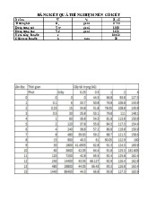
-With a crane with a crane with an axle force of Q = 8T and a span of L = 29.5m, look up table II.3, page 87, the book Steel frame
design of a single-storey, single-span industrial building – Dr. Pham Minh Ha, we have the following parameters: Axial Span Height DistantZ Width Bottom Craine Roller Pressure Pressure strength L min (mm) wieght Pmin (kN) k (m) gabarit gabarit width weight Pmax Q (T) G (T) H k (mm) Bk Kk Gxe (T) (kN) (mm) (mm) 8 28 960 180 5300 4600 14.78 0.605 70.2 29.5 I. Vertical Dimension:
- Height from the crane rail surface to the bottom of the crossbar:
H2 = Hk + bk = 0.96 + 0.2 = 1.16 (m).
With bk = 0.2 (m) - safety gap between the crane and the crossbar.
Hk = 0.96 (m) - according to the selected crane parameters. select H2 = 1.2 (m).
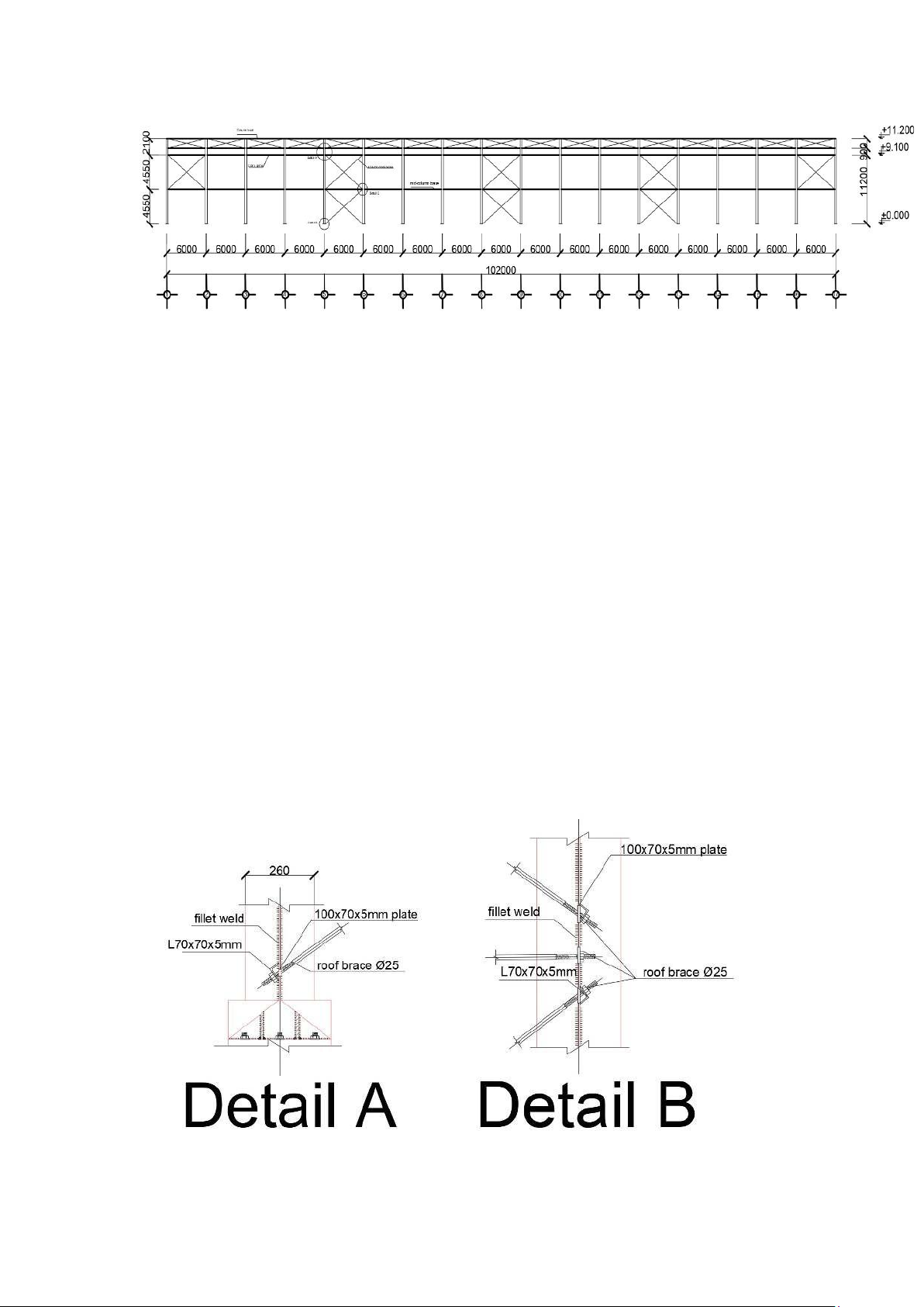
- The height of the frame column, calculated from the foundation to the bottom of the crossbar:
H = H1 + H2 + H3 = 10 + 1.2 + 0 = 11.2 (m). Which:
H1 - Rail top elevation, H1 = 10 (m).
H3 - The pillar is buried under the foundation H3 = 0.
- The height of the column is calculated from the shoulder of the crane beam support column to the bottom of the crossbar :
Ht = H2 + Hdct + Hr = 1.2 + 0.7 + 0.2 = 2.1 (m). Which :
+ Hdct - Crane Beam Height, therefore: Hdct = (1/8 – 1/10)B =
(1/8 – 1/10).6 = (0.6 – 0.75)m.
=> Preliminary selection Hdct= 0.7 (m).
+ Hr - Height of rails and cushions, select Hr=0.2 (m).
- The height of the column is calculated from the foundation to the top of the shoulder of
the column: Hd = H - Ht = 11.2 – 2.1 = 9.1 (m).
II. Horizontal Dimensions:
- Consider the positioning shaft to coincide with the middle of the column (a = h/2).
- Distance from the positioning shaft to the crane rail shaft:
with Lk = 28 (m) – Crane span, select based on catalog
L= 29.5 (m) – Frame span, take according to design requirements.
- The cross-section height of the column is selected according to the hardness requirements:
Select h = 0.7 (m) = 70 (cm).
- Check the gap between the crane and the frame column: z = L1 – h/2 = 0.75 – 0.7/2 = 0.4 (m) > zmin = 0.18 (m).
Preliminary selection of sections :
1 . Preliminary selection of column size and cross-section :
- The column cross-section height is selected according to the hardness requirement: => select h=700mm
- The cross-section width of the column is selected according to the structural
conditions and stiffness: bf = (0.3÷0.5)h = (0.3÷0.5) x 700 = (210 ÷ 350) mm => Select bf = 300 mm - Web thickness: tw 1 1 h 1 1 700 (7 10) mm 6mm 70 100 70 100 => Select tw = 8 mm. - Wingspan thickness: =>Select tf = 10 mm.
- Column section as shown in the drawing:
Figure 1.1 Preliminary selection column cross-section
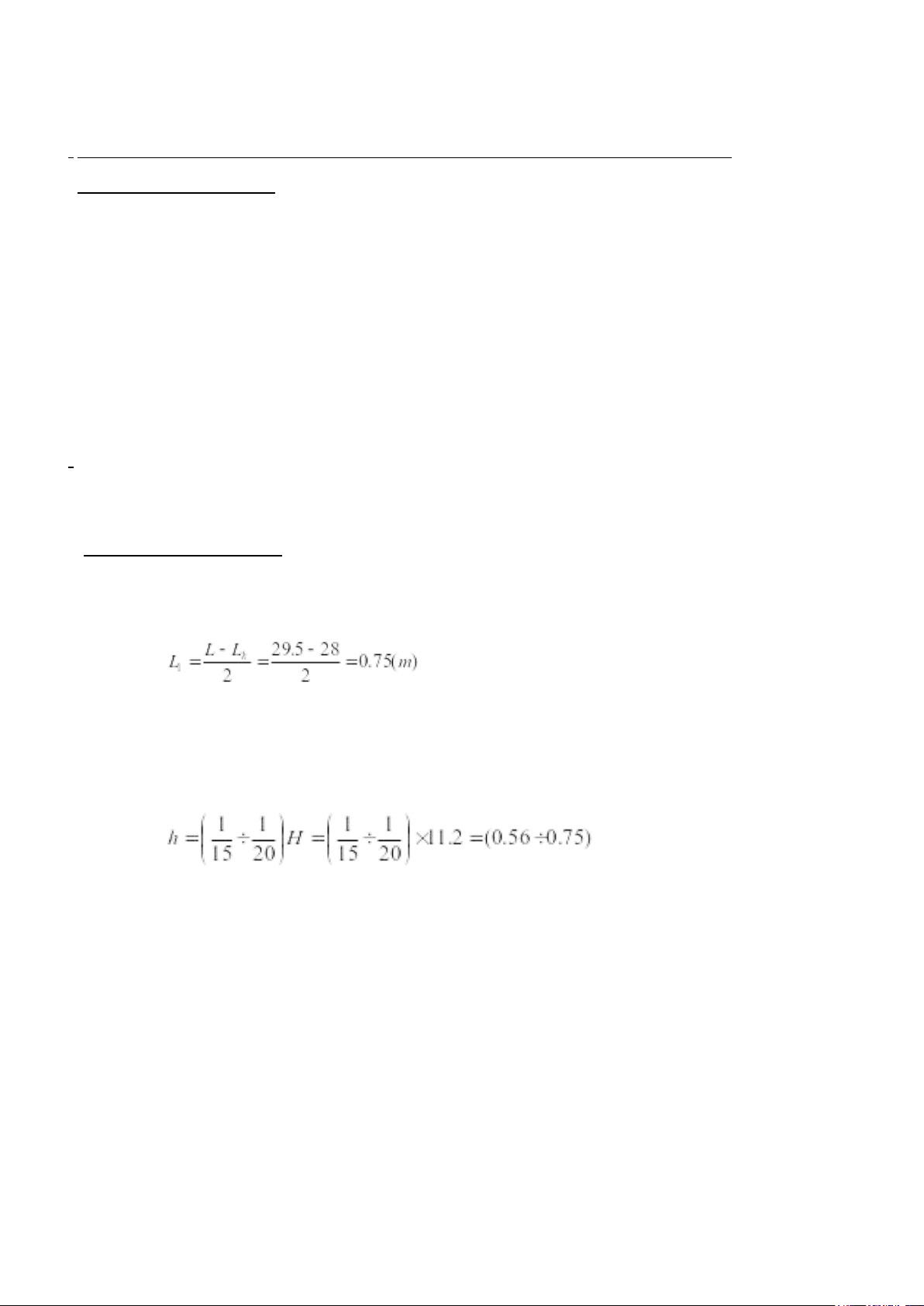
2.Choose a crossbar section:
- The end of the beam section (cross section change): select = (0.3 ; 0.5) 5 0 0 S e l e c t bxl =300mm Hxl=500mm Bxl=300mm tw = 8mm. tf = 10mm. Figure 1.2. Preliminary
selection of beam head section
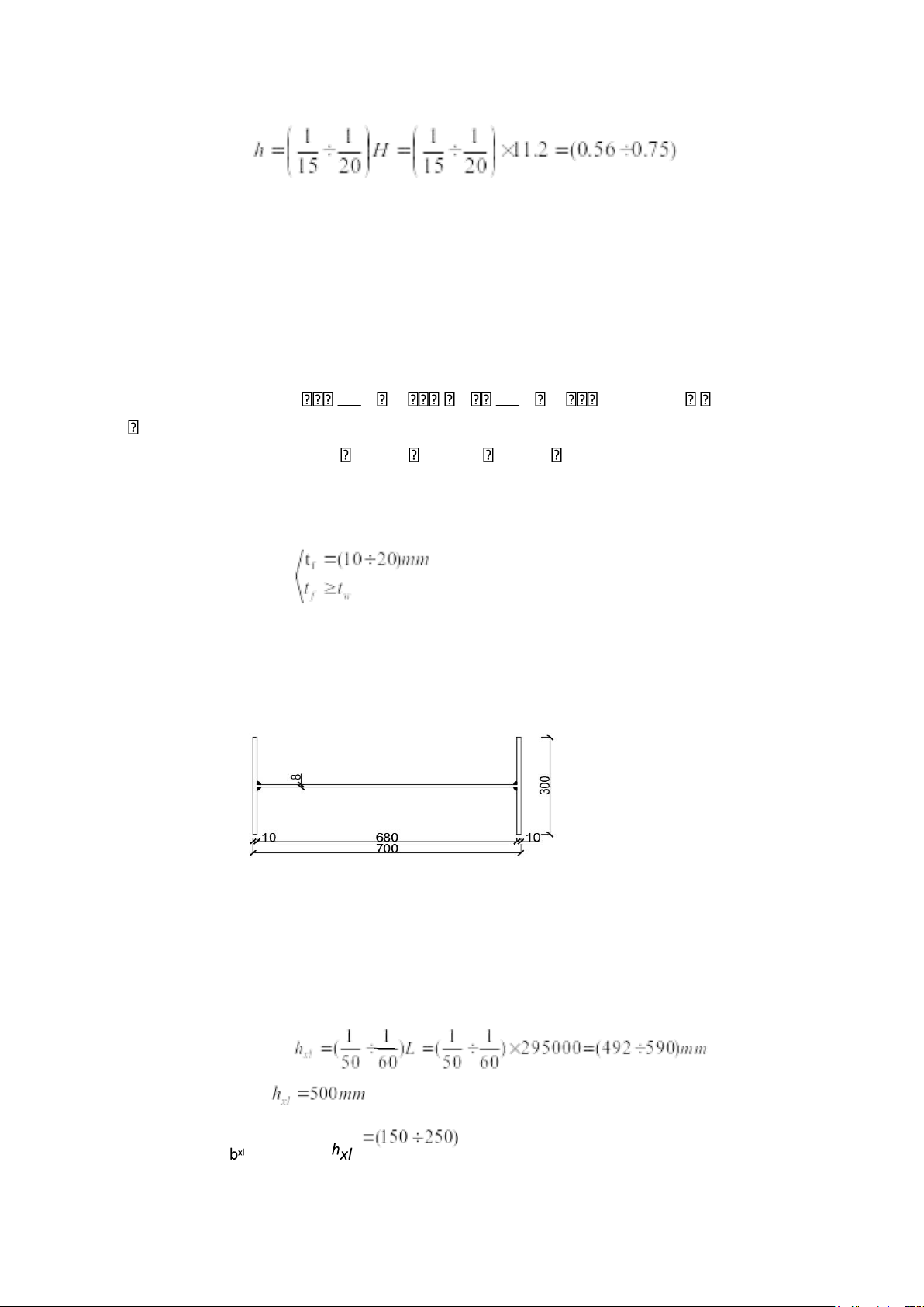
- End of the beam section (constant cross-section): hxn= 300 mm bxn= 300mm tw= 6mm. tf= 10mm.
Figure 1.3. Preliminary cross-section at the end of the bar
3.Preliminary selection of the size and cross-section of the roof window: a. Roof window size
- According to architectural and lighting requirements, we choose a roof door that
runs the entire length of the house except for 2 gable compartments with the following parameters:
+ Roof Window Width Lcm = (1/2 1/5 )L →Lcm = 8m.
+ The height of the roof window is equal to Hcm = 2m.
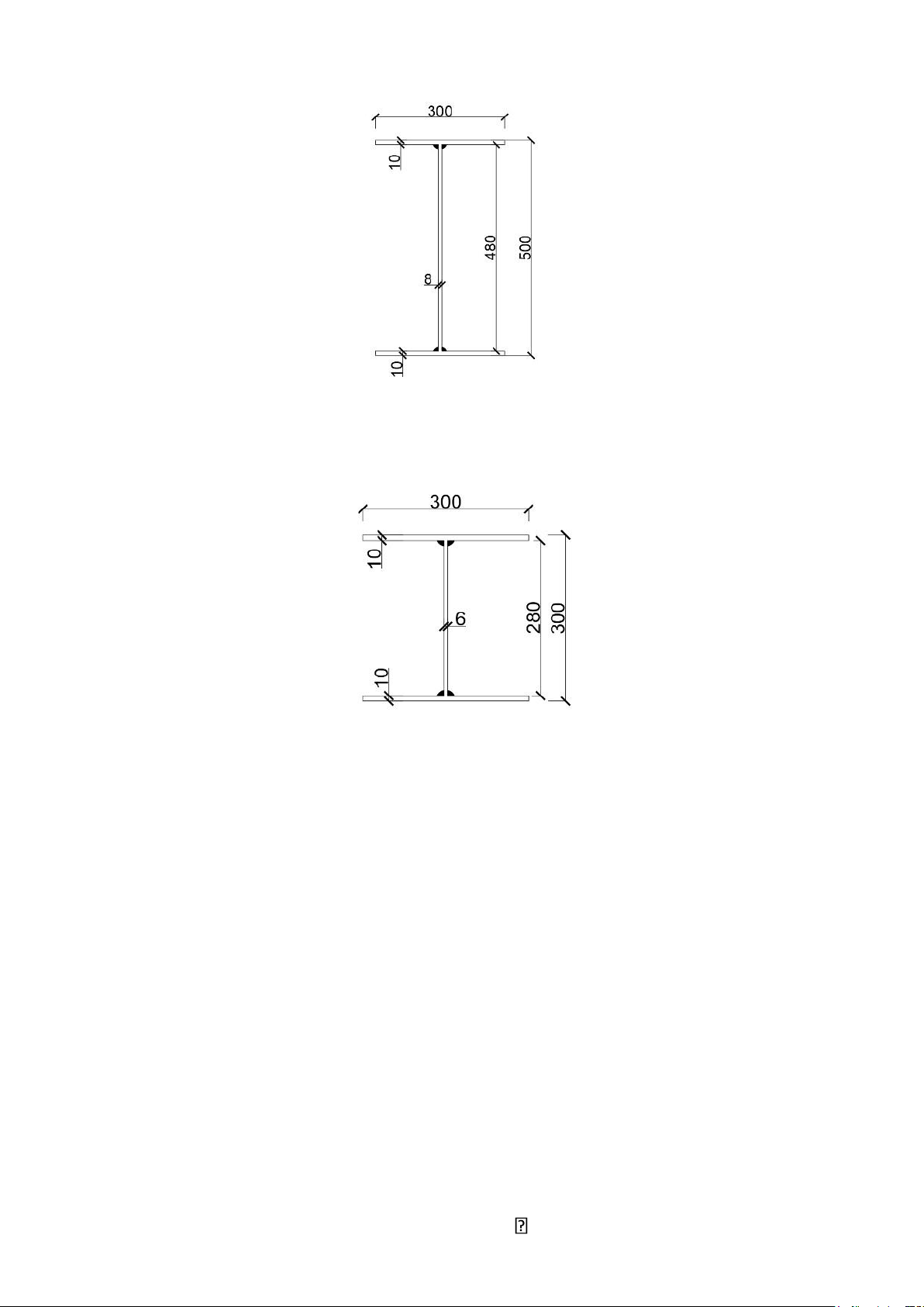
+ The slope of the roof is taken by the roof slope of the i=15%. b. Roof window section
Preliminary selection: I15 shaped steel, refer to I15 shaped steel on the market, we
have the following size parameters:
Figure 1.4. The section of the skylight pole is preliminary selected
Figure 1.5. The main dimensions of the horizontal frame CHAPTER II BRACE SYSTEM DESIGN ------ I.
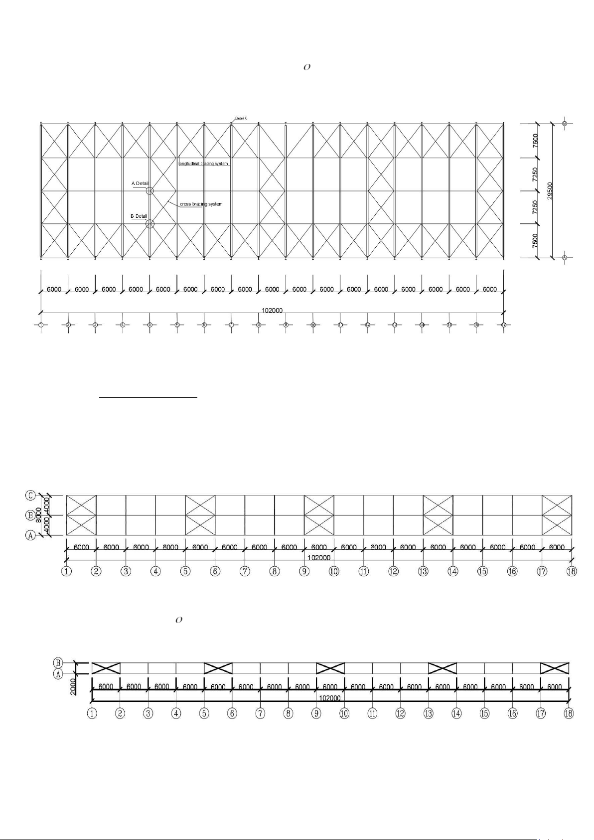
ROOF STRENGTH SYSTEM AND COLUMN STRENGTH SYSTEM. 1. Roof bracing system.
Arranged in the plane of the upper wing at the two gable ends (or near the gable end),
at the beginning of the temperature blocks and in the middle of the house depending on the
length of the house, so that the distance between
The braces are arranged no more than 5 column steps apart. The web of the two cross beams
next to each other are connected by diagonal cross braces.
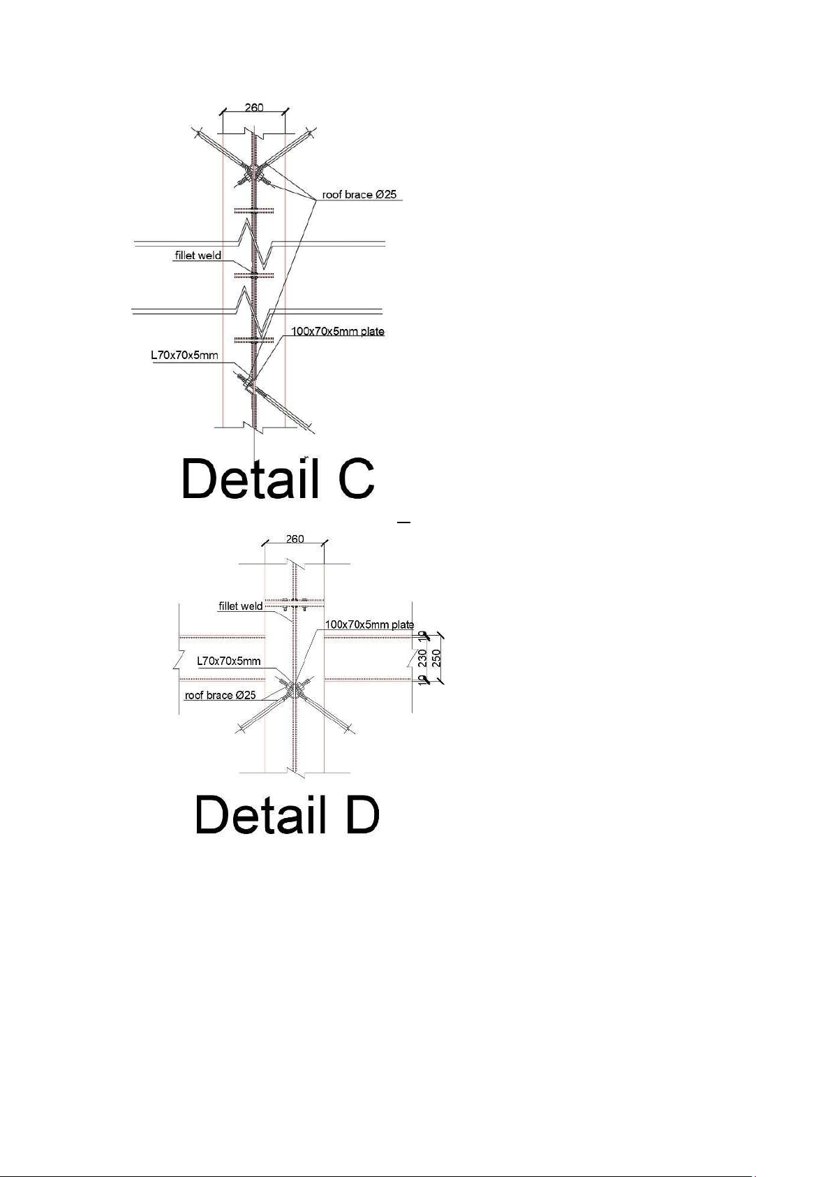
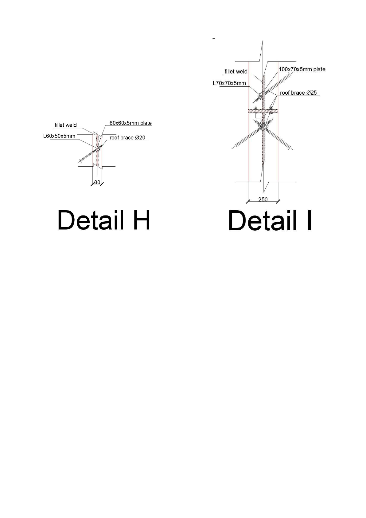
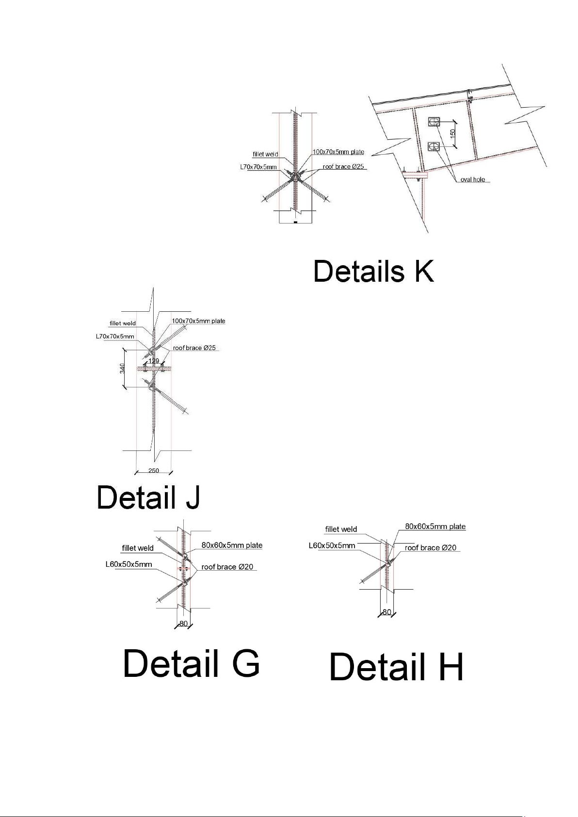
These diagonal braces can be angle steel, round steel or galvanized steel cable
diameter not less than 12mm, round steel diameter not less than 20. 20.
=>We choose roof tie bars made of round steel
Figure 2.1 Plan of roof bracing arrangement 2. Column bracing system. -
The column bracing system has the effect of ensuring the longitudinal rigidity of the house
and keeping the columns stable, receiving and transmitÝng to the foundation the longitudinal
loads such as the wind load on the return wall, the vertical braking force of the crane. The column
bracing system consists of diagonal bracing rods arranged within the upper and lower columns at
the pavilions with roof bracing systems. -
The house has a crane with a lifting capacity of 8 tons, so we use round steel with a diameter of not less than 20mm. =>select round steel 20
We choose column joists and column head joists are C-shaped steel with the number 6CS2.5x105. The
self-weight of the steel is g = 6.29Kg/m.
Figure 2.2. Arrangement of column bracing system
II. ROOF DOOR BRACING SYSTEM.
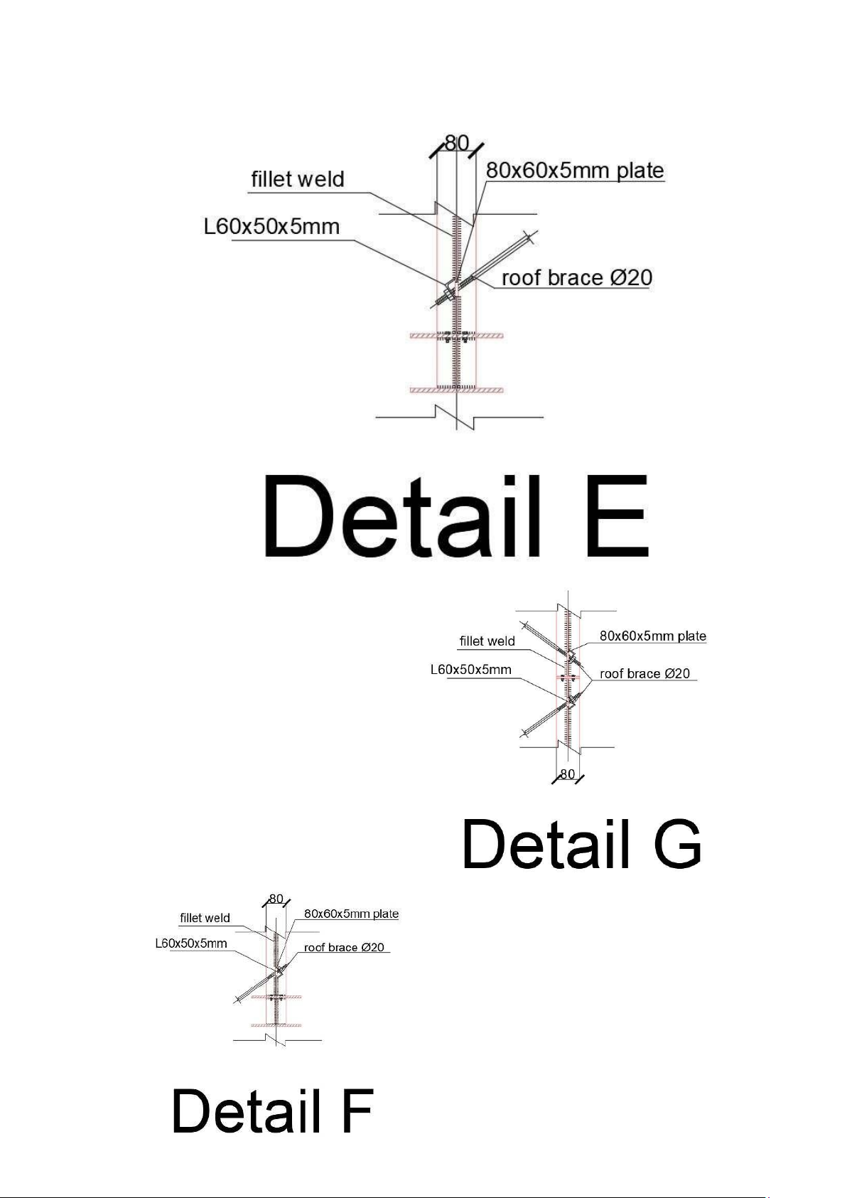
- The roof door bracing system is also arranged similarly to the roof bracing system, but the
roof door bracing system only has upper wing bracing and vertical bracing.
1. Bracing the upper wings.
Figure 2.3. The layout of the wing bracing system on the roof door 2. Bracing.
Figure 2.4. Arrangement of roof door bracing system
I choose the column tie rod and the head tie of the roof door column is C-shaped steel:
C200x65x20x3. The self-weight of the steel is g = 6.29Kg/m. Details: D
Tài liệu liên quan:
-
Tính toán cầu thang bê tông cốt thép 2 | Môn Cơ học kết cấu - Đại học Cần Thơ
172 86 -
Bài Tập Chương 2 - Cơ Cấu và Vận Tốc Quay | Môn Cơ học kết cấu - Đại học Cần Thơ
109 55 -
Bài Tập Bài 2: Phân Tích Dung Trọng và Độ Chứa Nước | Môn Cơ học kết cấu - Đại học Cần Thơ
108 54 -
Bài 5 - Thí nghiệm nén cố kết và kết quả phân tích | Môn Cơ học kết cấu - Đại học Cần Thơ
166 83