Tham khảo thêm Fast DC Offset Removal for Accurate Phasor Estimation using Half Cycle Data Window
Tham khảo thêm Fast DC Offset Removal for Accurate Phasor Estimation using Half Cycle Data Window giúp sinh viên tham khảo, ôn luyện và phục vụ nhu cầu học tập của mình cụ thể là có định hướng, ôn tập, nắm vững kiến thức môn học và làm bài tốt trong những bài kiểm tra, bài tiểu luận, bài tập kết thúc học phần, từ đó học tập tốt và có kết quả cao cũng như có thể vận dụng tốt những kiến thức mình đã học
Môn: Công nghệ phần mềm (CNPM1) 40 tài liệu
Trường: Trường Đại học Bách khoa, Đại học Đà Nẵng 1.7 K tài liệu
Tác giả:


Preview text:
J. Electr. Comput. Eng. Innovations, 10(2): 341-350, 2022
Journal homepage: http://www.jecei.sru.ac.ir Research paper
Fast DC Offset Removal for Accurate Phasor Estimation using Half- Cycle Data Window H. Sardari1, B.
Mozafari1,*, H A. Shayanfar . 2
1Department of Electrical and Computer Engineering, Science and Research Branch, Islamic Azad University, Tehran, Iran.
2Department of Electrical Engineering, Iran University of Science and Technology, Tehran, Iran. Article Info Abstract
Background and Objectives: Current and voltage signals' distortion caused Article History:
by the fault in the power system has negative effects upon the operation of Received: 03 September 2021
the protective devices. One of the influencing factors is the existence of the Reviewed 15 October 2021
exponential DC which can significantly distort the signals and lead to a Revised 11 November 2021
possible malfunction of the protective devices, especial y distance and over- Accepted 20 December 2021
current relays. The main problem is the lack of clarity about this component
due to the dependence of its time constant and initial amplitude to the
configuration of the electrical grid, location and resistance of faulty point. Keywords:
This makes it hard to extract the main frequency phasors of the voltage and Phasor estimation current. Digital filter
Methods: Considering the importance of a fast clearance of the fault, this
paper offers a method for an effective and fast removal of the decaying-DC HCFA
that employs a data window with a length that is equal to the half cycle of Mimic filter
the main frequency, while the conventional methods mostly use data from Exponential decaying-DC
one cycle or even more. The proposed method is based upon the extraction component
of the decaying-DC component's parameters. Synchrophasor measurements
Results: The efficiency of this method is compared to the conventional
Fourier algorithm of Half-Cycle (HCFA) and the mimic filter plus the HCFA.
Conclusion: The outcomes display that the proposed method presents a
*Corresponding Author’s E-mail
better efficiency from the point of view of the speed and the accuracy of
Address: mozafari@srbiau.ac.ir
convergence to the final results.
©2022 JECEI. All rights reserved. Introduction
Since the most of the protective relays such as
distance and over-current relays operate based on the
Fast fault clearance in the power system is a crucial
main phasors of the voltages and currents, the employed
requirement for the system operation. Its main purpose
digital protective algorithms should be designed so that
is to separate the grid faulty areas and to prevent the
they eliminate the DC component and harmonics.
instability. This is performed by the operation of
Otherwise, the proper function of the protective relay
protective relays instal ed in the power system and has
may be disrupted due to any these quantities. For
to happen in a fraction of a power frequency cycle. Input
instance, presence of the decaying-DC in the current
signals of different relays are filtered according to the
signal wil lead to reduction of the impedance obtained
protective logic and their operation by removing the
in the distance relay and the overreach phenomenon.
unwanted quantities and only preserving the desired
Consequently, the relay reacts for a fault which has not ones [1].
happened in its operational zone.
Doi: 10.22061/JECEI.2021.8205.492 341 H. Sardari et al.
Algorithms used in digital filters, known as phasor
computing. So, it requires two extra samples. The
estimation algorithms, can structural y be classified as
method in [19] eliminates the DC impact by means of the fol ows:
difference between the outputs of the FCDFT for even
a) Algorithms based on the smal window data, such as:
and odd samples. The method proposed in [20]
i) The Sample and Its First Derivative method by
calculates the value of the actual DC offset by integrating
Mann-Morrison [2], i ) The First and the Second
the input signal. And then, the DC component is
Derivative method by Gilchrist-Rockfel er-Udern [3],
subtracted from the main signal for each sample. In [21],
and i i) Two Samples method by Mokino-Miki [4].
the DC component impact is removed by combining the
b) Algorithms based on the orthogonal such as: Fourier
outputs of FCDFT for even and odd samples extracted by
Filter algorithm [5], [6] and its products i.e. Cosine
decimation of the full cycle data window by two and by
and Sinusoidal Filters as wel as the Walsh Filter four.
algorithm [7] and its products i.e. CAL and SAL. The FCDFT output in [2 ] 2 is corrected by integrating
c) The Least Error Squares algorithms (LES), such as: i)
the input signal in a full cycle data window. To consider
Integral LSQ Fit [8], i ) Power Series LSQ Fit [9], and i i)
the changing frequency scenario of the electric network,
Multi-Variable Series LSQ technique [1 ] 0 . [2 ]
3 proposes LES method iteratively which fulfil s the
d) Algorithms based on the Kalman Filter [1 ] 1 .
steady state and dynamic performance criteria of the
The conventional Discrete Fourier Transform, DFT i.e.
IEEE standard for Synchrophasor Measurements for
the group (b) algorithm, is the most sought-after
Power Systems [24]. The proposed method in [23]
algorithm used in the digital protection because of its
requires extra memory for storing LES filter coefficients
proper operation and the ease of implementation. DFT of various frequencies.
algorithms are classified into Half-Cycle and Full-Cycle
The method in [25] computes the amplitude of the algorithms.
main frequency component by combining the FCDFT
The DFT cannot eliminate the DC component because
outputs filters for odd and even samples. In [26], the
of its non-periodic nature and large frequency spectrum.
decaying-DC parameters are calculated by integrating
In the recent years, some algorithms are offered in order
the fault current signal in a full cycle. Then, the DC is
to eliminate or to weaken the adverse aspects of the
subtracted from the main fault current.
exponential DC component in the output of the full-cycle
The method in [27] uses MATLAB's fsolve function to algorithms [1 ] 2 -[4 ]
0 . In [12], a mimic filter with the
estimate the fundamental frequency fault signal
Fourier algorithm is proposed to remove the DC
component which is developed for two cases including i)
component. In this method, if the time constants (τ) of
decaying-DC with known time constant, and i ) unknown
the decaying-DC component and the mimic filter are the
time constant. For improving the fault location
same, the impact of the DC component can be estimates, [2 ]
8 removes the effect of the DC component completely removed.
by curve fitting by means of Non-Linear Least Squares In [1 ]
2 , the decaying-DC parameters are calculated by
method. Algorithms based upon wavelet transform [29]
two Full-Cycle successive outputs Discrete Fourier and neural network [3 ] 0 have been utilized for the
Transform (FCDFT). In the modified version of the
protection and phasor estimation applications. method in [1 ] 2 by the same authors [1 ] 4 , the effect of
Recently, phasor estimation under dynamic
analog anti-aliasing filter i.e. production of additional
conditions has been under investigation. The methods in
decaying-DC has been overcome. The method proposed [3 ] 1 -[3 ]
3 propose dynamic phasor estimation which in [1 ]
5 uses two paral el DFT filters, one of them is set to
consider the off-nominal frequency condition. These
the main frequency and the other to the mt h harmonic.
methods may produce more accurate results for phasor
The latter is used for calculating the decaying-DC
estimation. However, they entail higher computational component's parameters.
burden. In one of the most recent algorithms in this In [1 ]
6 , two partial sums are employed for complete
category, the DC amplitude and time constant are
removing the DC component's effects. One of the partial
calculated by applying Hilbert transform and integrating
sums is the sum of odd samples and the other is the sum
the fault current signals within one cycle [3 ] 3 . Hilbert
of even samples during a full cycle of the power
transform has been utilized due to its effectiveness in
frequency. The amplitude and τ of the DC component in
the analysis of time-varying signals. Over the past few [1 ]
7 are obtained by two mathematical expressions
years some studies are conducted to forecast
which directly use the values from four samples. This
phenomena with uncertainties [34]-[37]. In [34]
method, which can be used in both full-cycle and half-
Gaussian model, in [35] ensemble learning based
cycle data windows, requires two extra samples.
method and in [36] deep learning-based approach are In [1 ]
8 , the phasor is computed from three used for forecasting.
consecutive DFT estimates by using a recursive
Al of the above methods are proposed for the full 342
J. Electr. Comput. Eng. Innovations, 10(2): 341-350, 2022
Fast DC Offset Removal for Accurate Phasor Estimation using Half-Cycle Data Window
cycle algorithms and there are only few methods
in the generation of decaying-DC signal. The DC
proposed for the half cycle algorithms. Half-cycle
component considerably impacts the current signal
algorithms have a higher convergence speed, in the
where it has an insignificant influence of the voltage
order of two times faster than full cycle methods. Among
signal. There have been reports on up to 15% error in
the most important half-cycle algorithms, the Half-Cycle
the phasor estimation by the deteriorative effect of DC
DFT algorithm (HCDFT) and the combination of digital
component on the calculations [1 ] 2 . Besides, DC
mimic filter and the HCDFT algorithm can be nominated.
component parameters cannot be determined with a
These methods are unable to completely remove the
high level of certainty. For instance, its time constant can
effects of the DC component [38].
depend on the configuration of the grid, the resistance
One of the recently proposed methods to extract the
and the location of fault and is specified by means of the
phasor by means of the half-cycle data window is
X/R ratio seen from the fault point in general. For highly presented in [3 ] 9 i
n which three offline look-up tables
resistive earth faults, decaying rate wil be so high that
have to be created prior to processing the input signal
the decaying-DC would decay in less than half a cycle in
for determining the decaying-DC component's some cases.
parameters and removing its effects from the main
General y, decaying-DC time constant range of
signal. The look-up tables should be referred to during
variation is from 0.5 a cycle up to 5 cycles. It is not an
the online process which in turn increases the
alternating signal and thus, contains a wide frequency computational burden.
spectrum. Therefore, convergence speed and accuracy The method in [4 ]
0 proposes a general modified DFT
of the digital filtering methods are affected which leads
algorithm, so that it is possible to employ the method in
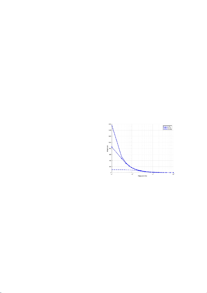
to errors in the estimated phasors. Fig. 1 shows the
both HCDFT and FCDFT algorithms. In this method, two
frequency spectrum of the DC component with different
successive outputs of the imaginary and real part filters time constants.
are combined to eliminate the DC impact. In the method proposed in [4 ]
0 , three paral el filters are used. In
addition, the data window length for HCDFT will be
n/2+1, where n is the number of samples per cycle. A
hybrid algorithm based upon integration and half-cycle
DFT is proposed in [41]. This method computes the DC
component parameters and the unwanted share of DC in
the phasor estimation. However, it requires two
movements in the sampling window.
In this paper, a method is presented to improve the
efficiency of the Half-Cycle algorithm against the DC
component. In the proposed method, the influence of
the decaying-DC is entirely eliminated by means of its
parameters’ estimation. The proposed method can be
used for a wide range of decaying-DC time constants and
it is not dependent on the amount of the time constant.
Fig. 1: Frequency spectrum of the DC component with various
This paper is structured as fol ows: the first section time constants.
introduces the problem description, the second section
As it can be observed, the ratio of low frequency
formulates the proposed method, the third section
component to high frequency one changes with the time
evaluates the performance of the proposed methods,
constant. In other words, a fast decaying-DC contains
and the final section concludes this work.
less low frequency components compared to a slow Problem Description decaying one.
The unpredictable nature of the fault signals in the The Proposed Method
power grid makes the main component phasor
In this part, the structure of the proposed method is
estimation a chal enging process. Under the usual
introduced. First, influence of the DC component on the
operating conditions, the voltage and current signals are
HCFA wil be examined and then, for removing this effect
almost clear sinusoidal with the main frequency of the a method wil be presented.
grid. However, after failures or disturbances in the grid,
these waveforms are distorted containing decaying-DC,
A. Effect of the Decaying-DC Component
harmonics, and the non-main frequency components
Let the input fault current signal contain: i) [1 ] 5 .
fundamental component, i ) first harmonic to pt h
The reactive-resistive feature of the network results
harmonics, i i) decaying-DC. It can be presented by the
J. Electr. Comput. Eng. Innovations, 10(2): 341-350, 2022 343 H. Sardari et al. formula below:
B. Determining Decaying-DC Component's Parameters ()
As it was mentioned in the previous subsection, to − = + ( + ) (1)
obtain the main frequency phasors, the main frequency = where
HCFA's output for the decaying-DC is required. According
I0 is the DC amplitude and τ i s i t s ti m e c o ns t ant. Ik
is kt hharmonic amplitude, ω to (4),
is a function of τ and amplitude of the DC
1 is main angular frequency, θ h
component. Therefore, the mentioned parameters must
k is of kt harmonic phase angle, and p is the largest
order of harmonic that exists in the waveform. be calculated first.
It is assumed that the harmonic components that
The current and voltage signals of the fault may
have higher orders than p have been eliminated in the
consist main frequency, decaying-DC, high-frequency
input using the anti-aliasing low-pass filter. The analog to
harmonics, and noise. Protective equipment use a filter
digital conversion is performed by an A/D converter as:
with anti-aliasing low-pass features in each analog
channel input to remove the high-frequency ( ) − = + ( + ) (2)
components. As a result, the components with the =
frequencies higher than the filter cut-off frequency of
where T represents the sampling tim e per i o d a nd n
the anti-aliasing filter do not show up in the channel
points to the nt hsample. output.
The main frequency HCFA generates its output using
Correspondingly, a Fourier filter of half-cycle set to a the fol owing equation:
harmonic frequency higher than the low-pass filter cut- −
off frequency can be designed so that the main = ( ) ( + )
frequency and the other harmonics wil not emerge in its (3) =
output. Consequently, the output wil only be influenced −
by the DC component. Time constant and Amplitude of = ( ) −
the DC can be calculated by the output of the mth = harmonic frequency HCFA. where
is output of the main frequency HCFA for
The Fourier filter of Half-Cycle is set to the mth
the total input signal, i.e., the signal that includes main
harmonic frequency. This frequency has to be higher
frequency, harmonics, and the decaying-DC, and N is the
than the low-pass filter cut-off frequency and lower than
quantity of samples per each cycle.
the half of the sampling frequency. Subsequently, output
The harmonic components with odd order are
of the Fourier filter of Half-Cycle wil only contain the
eliminated by the HCFA and the input signal does not
effect of decaying DC and it goes as fol ows: include even harmonics [4 ]
2 , the output wil only contain −
the main frequency and the DC. The main frequency − − = (6)
phasor wil be found by removing the DC from the =
output of this algorithm. The output of main frequency With the assumption that t he h mt ha r m o nic i s odd,
HCFA for the exponential DC input can be calculated as
one can rewrite the above equation as: fol ows: − + = (7) − − − − − + − − = = (4) − − where is the outcome o f t he m t h ha r monic = − where
is the output of main frequency HCFA; frequency Half-Cycle Fourier filter.
Dividing (7) into imaginary and real parts results in the
resulted from the DC component. Once
is determined, the output of main equations below, where −
is substituted for E. The real part R is:
frequency HCFA for the main frequency component can be calculated using: ( + ) ( ) = (8) + − ( ) = − (5)
and the imaginary part I is: where
is the output of main frequency HCFA for ( + )( − ( )
the main frequency component which is the main = (9) frequency phasor. + − ( ) According to (4), is a function of time By using (8 ) and (9), t he v al ue s fo r E and
constant and amplitude of the decaying-DC. Therefore, ( ) ( + ) can be calculated as:
to obtain the output of the HCFA for the decaying-DC, = (10)
these parameters have to be determined first. ( ) + ( ) 344
J. Electr. Comput. Eng. Innovations, 10(2): 341-350, 2022
Fast DC Offset Removal for Accurate Phasor Estimation using Half-Cycle Data Window ( Results and Discussion + ) ( + − ( )) = (11) ( )
Algorithms efficiency is being assessed by the
The above equations use imaginary and real parts of
application of the fol owing input signal:
the mt h harmonic frequency Half-Cycle Fourier () = ( + ) − − (12)
algorithm's output and the specified values of ( ) and (
) . By placing (10 )and (11) in in which I0, amplitude of the DC component, and I1,
(4), the main frequency Half-Cycle Fourier algorithm's
amplitude of the main frequency component are
output for the DC component is resulted. Final y, the
selected as 1 per-unit. i(t) is applied to the various
main frequency phasor of the input signal, , is
algorithms with a variable time constant of the decaying-
DC component (τ) and their sensitivity versus τ variation achieved via (5). is evaluated.
In line with the above explanations, it can be
To make a comparison between different methods,
observed that the proposed method requires two Half-
the performance indices (PI1 and PI 12 .
Cycle Fourier filters; one set to the fundamental 2) are utilized [ ]
The performance indices are defined based upon the
frequency and the other set to the mt hharmonic, where
output of the digital phasor extraction filters for the
m is odd. The main purpose of using the mth harmonic
input signal i(t). y(t) is the waveform of the filter's output
Fourier filtering is to acquire the parameters of decaying-
for the applied input signal. y(t) oscil ates around 1 per-
DC. The needed calculations of the proposed method
unit before permanently settling in this value. The first
are: i) the implementation of two Fourier filters of Half-
performance index PI1 is calculated using the fol owing
Cycle and i ) the calculations pertaining to (10), (11), (4 ,) equation:
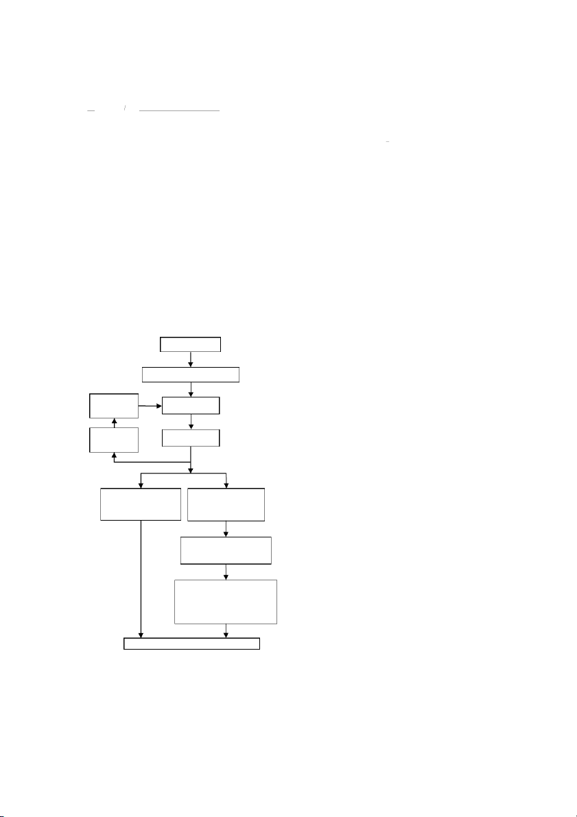
and (5 .) The proposed method flowchart is il ustrated in Fig. 2. ( ) = −() (13) Input signal As soon as y(t)'s a m pli t ude e x c e e ds 1 pe r- unit, the i(t)
integration starts (T0) and proceeds until NT, which
represents an integer number of the main frequency Anti-aliasing low-pass filter
cycles. In the simulations, let N be 3. PI1 represents the
extent of the amplitude oscil ations around the steady- Sampling rate
state final value in the filter's output in the presence of Sample & Hold adaptation
the DC component in the input.
The second performance index PI2 is equal to the Frequency
highest overshoot percentage in y(t)'s amplitude. There A/D conversion estimation
is a straight relevance between this index and the i(n)
protective devices' overreach potential. ( ) ( = () − ) (14)
As much as these indices get closer to zero, the higher Half-Cycle Fourier filter Half-Cycle Fourier filter
quality of the tested algorithm is inferred. The input set to the main set to the mth
signal's sampling rate is 36 samples per cycle and the frequency (HCDFT1) harmonic (HCDFTm)
value for m is selected as 13 for the proposed method.
The sampling window used in the simulations is the half
of the main frequency cycle that means 18 samples. Compute DC parameters by
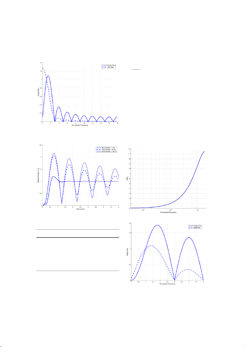
The frequency response of the Half-Cycle Fourier filter means of (10) and (11)
set to the main frequency is presented in Fig. 3. As it can
be observed, this filter cannot remove the decaying-DC
component when used standalone. The time response Determine the impact of DC
generated by applying the input signal to the HCFA is component on the main il ustrated in Fig. 4. frequency Half-Cycle Fourier
The values for the performance indices of the HCFA using (4)
versus τ variation in the range of 0.5 cycle to 5 cycles are presented in Table 1. Estimate the phasor using (5)
If the current waveform passes a mimic circuit
including a series resistor and inductor, the exponential
Fig. 2: The proposed method flowchart for the phasor
decaying component wil be removed or deteriorated in estimation.
the circuit's output. The transfer function for the mimic
J. Electr. Comput. Eng. Innovations, 10(2): 341-350, 2022 345 H. Sardari et al.
circuit in the Laplace domain would be:
effect wil be significantly reduced. The mimic circuit ( ) ( = + ) (15)
including a resistor and an inductor can also be digital y
modeled. In the case S is replaced using the fol owing
where τ1 is the time constant which mimic filter is set to.
equation, the Z domain representation of the mimic
circuit's transfer function can be obtained: − − = (16) where ΔT is t he s a m pli ng pe ri o d.
The time constant is set to 50 ms in the mimic filter's
design which is approximately located in the middle of
its variation range. The digital mimic filter’s frequency
response is shown in Fig. 5. It is clear that the mimic
filter is a high-pass filter that means boosting the high
frequency components. Therefore, it is prone to high frequency noise.
By combining the digital mimic filter and the HCFA,
the performance of the HCFA in confronting with the
decaying-DC can be improved to some extent. The
frequency response of the combination of digital mimic
Fig. 3: Frequency response of the Half-Cycle Fourier filter for
filter and the HCFA is presented in Fig. 6. The time the main frequency.
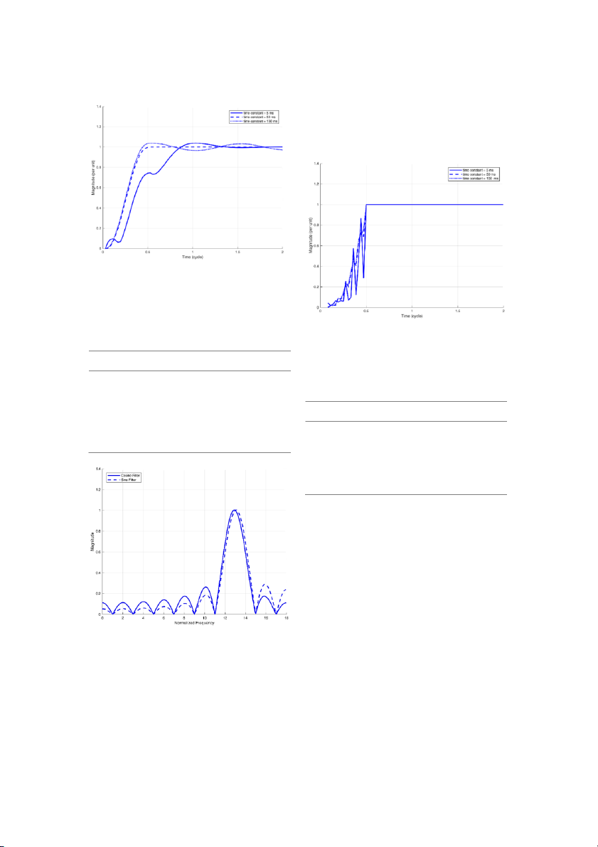
response obtained by applying the input signal to the
combination of the mimic filter and the HCFA is il ustrated in Fig. 7.
Fig. 4: Time response of the HCFA.
Fig. 5: Digital mimic filter’s frequency response.
Table 1: Performance Indices for the HCFA Time constant (mSec) PI1 PI2 (%) 10 2.8692 49.1603 20 9.9800 78.5331 40 22.6705 99.7476 60 31.7330 108.1275 80 38.0549 112.6007 100 42.5512 115.3807
If the decaying component's time constant is equal to
τ1, its effect wil be eliminated in the output of the mimic
filter and if the time constant has a different value, its
Fig. 6: Frequency response of the digital mimic plus the HCFA. 346
J. Electr. Comput. Eng. Innovations, 10(2): 341-350, 2022
Fast DC Offset Removal for Accurate Phasor Estimation using Half-Cycle Data Window
(m=13) and the other is set to the main frequency. Fig. 8
demonstrates the frequency response of the Fourier
filter set to the 13th harmonic.
The time response obtained by applying the input
signal to the proposed algorithm is shown in Fig. 9.
Fig. 7: Time response of the combination of digital mimic filter and the HCFA.
Performance indices for the combination of digital
mimic filter and the HCFA are presented in Table 2.
Table 2: Performance Indices for the Combination of Digital
Fig. 9: Time response of the proposed algorithm. Mimic Filter and the HCFA
For the proposed algorithm the values of the
performance indices for τ variation in the range of 0.5 Time constant (mSec) PI1 PI2 (%)
cycle to 5 cycles are presented in Table 3. 10 0.054969 7.2968 20 0.046537 5.7402
Table 3: Performance Indices for the Proposed Algorithm 40 0.004078 1.4166 Time constant (mSec) PI 60 0.003376 1.1969 1 PI2 (%) 80 0.021745 2.8038 10 0.00 0.00 20 0.00 0.00 100 0.044052 3.8010 40 0.00 0.00 60 0.00 0.00 80 0.00 0.00 100 0.00 0.00
By a careful examination of the time responses
obtained from different methods, it can be observed
that the Half-Cycle Fourier filter and the combination of
digital mimic filter and the Half-Cycle Fourier both have
overshoots in their outputs. Whereas, the proposed
method does not have such overshoots and as soon as
the data window fil s with the valid fault data, its output
reaches the desired value. In addition, the proposed
method generates favorable responses for different time
constants and it is not dependent on the value of the τ.
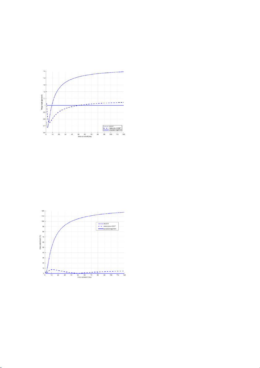
More simulations are performed to have a more vivid
representation of different algorithms' performance for
Fig. 8: Frequency response of the Fourier filter set to the 13th
a wider range of τ variations of the decaying-DC, where harmonic.
the τ varies from 1 to 120 ms. Outputs after fil ing their
By using two paral el Half-Cycle Fourier filters, impact
data windows with the fault data are shown in Fig. 10.
of the DC component upon the extracted phasor can be
The highest deviation of the HCFA from the desired
total y eliminated. As it was mentioned before, one of
output is 49.18% which happens in 120 ms time
these Half-Cycle Fourier filters is set to the mth harmonic
constant. The highest deviation from the desired output
J. Electr. Comput. Eng. Innovations, 10(2): 341-350, 2022 347 H. Sardari et al.
for the combination of digital mimic filter and the HCFA
robust against the impact of the DC component. The
is 25.40% happening in 5 ms time constant. The
proposed method estimates the phasors using a data
proposed method's output comes to the favorite value
window equal to the half cycle of the power grid's main
as soon as the data window fil s with the first half cycle frequency. data.
The proposed method utilizes two paral el filters set
to different frequencies, so that after fil ing the data
window with the fault data, precise and stable outputs
are generated. In the proposed method, once the data
window is fil ed with half-cycle data (n/2 of samples), the
main phasor component is a computed, while in the
presented method in reference [39] three look-up tables
are referred to during online processing which causes an
increase in computational work. The offered data
window length for HCDFT method is n/2+1 in reference [4 ]
0 which is one sample longer than that of our presented method.
Final y, in the proposed method of reference [41] it is
necessary to move the data window two samples. As a
result, the main phasor component wil be calculated
with a two-sample delay. Moreover, the Efficiency of the
Fig. 10: The extracted phasor at the end of the fault's first half
proposed method was compared to the HCFA and the cycle.
combination of digital mimic filter and the HCFA which
showed a higher speed and accuracy of the proposed
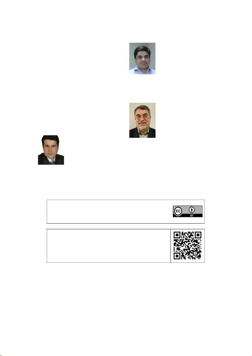
Fig. 11 demonstrates the variations of the highest
method. The performance indices (PI1, PI2) are calculated
overshoot in the algorithms output as a function of the
for various algorithms and the indices are almost zero
decaying-DC's time constant. The highest overshoot in
for the proposed method. The more these indices get
the HCFA is 117.27% happening in 120 ms time constant.
closer to zero, the higher quality of the tested algorithm
The highest overshoot in the combination of digital
is inferred and therefore the desired performance of the
mimic filter and the HCFA is 7.39% happening in 11 ms proposed method is confirmed.
time constant, whereas the highest overshoot in the
proposed method is 2.59% happening in 1 ms time Author Contributions
constant. As it can be observed, the proposed method
Authors have had an equal contribution in the
does not generate a large overshoot for a wide range of
problem and data analysis, interpreting the results and the time constant variation. writing the manuscript. Acknowledgement
Authors want to warmly acknowledge the kind helps
provided by Dr. Saeed RamezanJamaat for the writing
assistance and by Mr. Mehdi Bakhshandeh for proof reading of the manuscript. Conflict of Interest
The authors declare no potential conflict of interest
regarding the publication of this work. In addition, the
ethical issues including plagiarism, informed consent,
misconduct, data fabrication and, or falsification, double
publication and, or submission, and redundancy have
been completely witnessed by the authors. Abbreviations
Fig. 11: The highest overshoot in the extracted phasor. DC Direct Current Conclusion DFT Discrete Fourier Transform
In this paper, a method for extracting the main
frequency phasor was proposed which is favorably FCDFT
Full-Cycle Discrete Fourier Transform 348
J. Electr. Comput. Eng. Innovations, 10(2): 341-350, 2022
Fast DC Offset Removal for Accurate Phasor Estimation using Half-Cycle Data Window
[18] C.S. Chen, C.W. Liu, J.A. Jiang, "Application of combined adaptive HCDFT
Half-Cycle Discrete Fourier Transform
fourier filtering technique and fault detector to fast distance
protection," IEEE Trans. Power Deliv., 21(2): 619-626, 2006. HCFA Half-Cycle Fourier Algorithm
[19] S.H. Kang, D.G. Lee, S.R. Nam, P.A. Crossley, Y.C. Kang, "Fourier
transform-based modified phasor estimation method immune to References
the effect of the DC offsets," IEEE Trans. Power Deliv., 24(3) : 1104-1111, 2009.
[1] E.O. Schweitzer, D. Hou, "Filtering for protective relays," in Proc.
IEEE WESCANEX 93 Communications, Computers and Power in
[20] K.N.A. Al-Tal aq, H.D. Al-Sharai, M.E. El-Hawary, "Online algorithm
the Modern Environment., 1993. for removal of decaying D -
C Offset from fault currents," Electr. Power Sys. Re . s , 81(7) :1627-1629, 2011.
[2] B.J. Mann, I.F. Morrison, "Digital calculation of impedance for
transmission line protection," IEEE Trans. Power Appar., PAS-
[21] K.M. Silva, B.F. Küsel, "DFT based phasor estimation algorithm for 90(1): 270-279, 1971.
numerical digital relaying," Electron. Lett., 49(6): 412-414, 2013.
[3] G.B. Gilchrist, G.D. Rockefel er, E.A. Udren, "High-speed distance
[22] M.R. Dadash Zadeh, Z. Zhang, "A new DFT-based current phasor
relaying using a digital computer, Part I: System description," IEEE
estimation for numerical protective relaying," IEEE Trans. Power
Trans. Power Appar., PAS-91(3): 1235-1243, 1972.
Deliv., 28(4): 2172-2179, 2013.
[23] S. Das, T. Sidhu, "A simple synchrophasor estimation algorithm
[4] J. Makino, Y. Miki, "Study of operating principles and digital filters
considering IEEE standard C37.118.1-2011 and protection
for protective relays with a digital computer," in Proc. Conf. Pap.
IEEE Power. Eng. Soc., 1975: 661-668, 1975.
requirements," IEEE Trans. Instru., 62(10): 2704-2715, 2013.
[24] IEEE Standard for Synchrophasor Measurements for Power
[5] M. Ramamoorty, "Application of digital computers to power
Systems, IEEE Standard C37.118.1, 2011 (Revision of IEEE Std
system protection," J. Inst. Eng., 52(10): 235-238, 1972. C37.118, 2005).
[6] P.G. McLaren, M.A. Redfern, "Fourier-series techniques applied to
[25] A. Rahmati, R. Adhami, "An accurate filtering technique to
distance protection," in Proc. Institution of Electrical Engineers
mitigate transient decaying DC offset," IEEE Trans. Power Deliv.,
Conf., 122(11): 1301-1305, 1975. 29(2): 966-968, 2013.
[7] J.W. Horton, "The use of walsh function for high-speed digital
[26] A. Akbar Abdoos, S.A. Gholamian, M. Farzinfar, "Accurate and fast
relaying," in IEEE PES Summer Meeting, Paper A 75 582 7: 1-9 ,
DC offset removal method for digital relaying schemes," IET 1975.
Gener. Transm. Distrib., 10(8): 1769-1777, 2016.
[8] R.G. Luckett, P.J. Munday, B.E. Murray, "A substation-based
[27] S.A. Gopalan, Y. Mishra, V. Sreeram, H.H.C. Iu, "An improved
computer for control and protection," in IEE Conf. on
algorithm to remove DC offsets from fault current signals," IEEE
Developments in Power System Protection, Pub. 125: 252-260,
Trans. Power Deliv., 32(2): 749-756, 2016. 1975.
[28] K.W. Min, S. Santoso, "DC offset removal algorithm for improving
[9] A.W. Brooks, "Distance relaying using least-squares estimates of
location estimates of momentary faults," IEEE Trans. Smart Grid,
voltage, current and impedance," in Proc. IEEE PICA Conf., 77CH 9(6): 5503-5511, 2017. 1131-2 PWR: 394-402, 1977.
[29] A.A. Yusuff, A.A. Jimoh, J.L. Munda, "Stationary wavelet transform
[10] M.S. Sachdev, M.A. Baribeau, "A new algorithm for digital
and single differentiator based decaying DC-Offset filtering in
impedance relays," IEEE Trans. Power Appar., PAS-98(6): 2232-
post fault measurements," Measurement, 47: 919-928, 2013. 2240, 1979.
[30] C.D.L. da Silva, G. Cardoso Junior, L. Mariotto, G. Marchesan,
[11] A.A. Girgis, R.G. Brown, "Application of kalman filtering in
"Phasor estimation in power systems using a neural network with
computer relaying," IEEE Trans. Power Appar., PAS-100(7): 3387-
online training for numerical relays purposes," IET Sci. Meas. 3397, 1981.
Technol., 9(7): 836-841, 2015.
[12] G. Benmouyal, "Removal of DC-offset in current waveforms using
[31] R.K. Mai, L. Fu, Z.Y. Dong, K.P. Wong, Z.Q. Bo, H.B. Xu, "Dynamic
digital mimic filtering," IEEE Trans. Power Deliv., 10(2): 621-630,
phasor and frequency estimators considering decaying DC 1995.
components," IEEE Trans. Power Sys., 27(2): 671-681, 2011.
[13] J.C. Gu, S.Li. Yu, "Removal of DC offset in current and voltage
[32] P. Banerjee, S.C. Srivastava, "An effective dynamic current phasor
signals using a novel fourier filter algorithm," IEEE Trans. Power
estimator for synchrophasor measurements," IEEE Trans. Instru., Deliv., 15(1): 73-79, 2000. 64(3): 625-637, 2014.
[14] S.L. Yu, J.C. Gu, "Removal of decaying DC in current and voltage
[33] M. Tajdinian, M. Zareian Jahromi, K. Mohseni, S. Montaser
signals using a modified fourier filter algorithm," IEEE Trans.
Kouhsari, "An analytical approach for removal of decaying DC
Power Deliv., 16(3): 372-379, 2001.
component considering frequency deviation," Electr. Power Sys. Res., 130: 208-219, 2015.
[15] T. Sidhu, X. Zhang, F. Albas, M. Sachdev, "Discrete-Fourier-
transform-based technique for removal of decaying DC offset
[34] A. Ahmadpour, S. Gholami Farkoush, "Gaussian models for
from phasor estimates," IEE Proc. Gener. Transm. Distrib., 150(6):
probabilistic and deterministic Wind Power Prediction: Wind farm 745-752, 2003.
and regional," Int. J. Hydrogen Energy, 45(51): 27779-27791, 2020.
[16] Y. Guo, M. Kezunovic, D. Chen, "Simplified algorithms for removal
of the effect of exponential y decaying dc-offset on fourier
[35] J. Lee, W. Wang, F. Harrou, Y. Sun, "Wind Power prediction using
algorithm," IEEE Trans. Power Deliv., 18(3): 711-717, 2003.
ensemble learning-based models," IEEE Access, 8: 61517-61527, 2020.
[17] J.F. Miñambres Argüel es, M.A. Zorrozua Arrieta, J. Lázaro
[36] S. Sadeghi, H. Jahangir, B. Vatandoust, M. Aliakbar Golkar, A.
Domínguez, B. Larrea Jaurrieta, M. Sánchez Benito, "A new
method for decaying DC offset removal for digital protective
Ahmadian, A. Elkamel, "Optimal bidding strategy of a virtual
relays," Electr. Power Sys. Re . s , 76(4): 194-199, 2005.
power plant in day-ahead energy and frequency regulation
J. Electr. Comput. Eng. Innovations, 10(2): 341-350, 2022 349 H. Sardari et al.
markets: A deep learning-based approach," Int. J. Electr. Power
Babak Mozafari received the B.Sc., M.Sc., and Energy Syst., 127, 2020.
Ph.D. degrees in electrical engineering from
Sharif University of Technology, Tehran, Iran,
[37] J. Guan, J. Lin, J. Guan, E. Mokaramian, "A novel probabilistic
in 1998, 2001, and 2007, respectively.
short-term wind energy forecasting model based on an improved
Currently, he is an associate professor in the
kernel density estimation," Int. J. Hydrogen Energy, 45(43):
Department of Electrical and Computer 23791-23808, 2020.
Engineering, Science and Research Branch,
[38] L. Wang, "Frequency responses of phasor-based microprocessor
Islamic Azad University, Tehran, Iran. His
relaying algorithms," IEEE Trans. Power Deliv., 14(1): 98-109,
research interests include power system 1999.
protection and power system dynamics.
[39] T.S. Sidhu, X. Zhang, V. Balamourougan, "A new half-cycle phasor
• Email: mozafari@srbiau.ac.ir
estimation algorithm," IEEE Trans. Power Deliv., 20(2): 1299-
• ORCID: 0000-0002-5699-2577 1305, 2005.
• Web of Science Researcher ID: AAT-5629-2021
• Scopus Author ID: 9743165700
[40] K.M. Silva, F.A.O. Nascimento, "Modified DFT-based phasor
• Homepage: https://faculty.srbiau.ac.ir/b-mozafari/fa
estimation algorithms for numerical relaying applications," IEEE
Trans. Power Deliv., 33(3): 1165-1173, 2017.
Heidar Al i Shayanfar received the B.Sc. and
[41] M. Tajdinian, A.R. Seifi, M. Al ahbakhshi, "Half-cycle method for
M.S.E. degrees in electrical engineering in
exponential y DC Components elimination applicable in phasor
1973 and 1979, respectively. He received the
estimation," IET Sci. Meas. Technol., 11(8): 1032-1042, 2017.
Ph.D. degree in electrical engineering from
Michigan State University, East Lansing, MI,
[42] B. Ram, Power System Protection and Switchgear, Tata McGraw-
USA, in 1981. Currently, he is a full professor Hil Education, 2011.
in the Department of Electrical Engineering, Biographies
Iran University of Science and Technology,
Tehran, Iran. His research interests include
Hamid Sardari received the B.Sc. and M.Sc.
the application of artificial intel igence to
degrees in electrical engineering from Iran
power system control design, dynamic load modeling, power system
University of Science and Technology, Tehran,
observability studies, voltage col apse, and congestion management in
Iran, in 2003 and 2006, respectively, and
a restructured power system, reliability improvement in distribution
Ph.D. from Islamic Azad University, Tehran,
systems, and reactive pricing in deregulated power systems. He has
Iran, in 2020. He is currently pursuing
published more than 490 technical papers in the international journals
research on fault location, digital protection,
and phasor estimation in Islamic Azad
and conferences proceedings. Dr. Shayanfar is a member of the Iranian University, Tehran, Iran.
Association of Electrical and Electronic Engineers.
• Email: sardari@iauet.ac.ir
• Email: hashayanfar@iust.ac.ir
• ORCID: 0000-0001-5032-5012
• ORCID: 0000-0002-2330-0546
• Web of Science Researcher ID: NA
• Web of Science Researcher ID: S-8857-2018
• Scopus Author ID: 36895082000
• Scopus Author ID: 55664571900
• Homepage: http://fani.iauet.ac.ir/fa/page/669/
• Homepage: https://its.iust.ac.ir/profile/en/hashayanfar Copyrights
©2022 The author(s). This is an open access article distributed under the terms of the
Creative Commons Attribution (CC BY 4.0), which permits unrestricted use, distribution,
and reproduction in any medium, as long as the original authors and source are cited. No
permission is required from the authors or the publishers.
How to cite this paper:
H. Sardari, B. Mozafari, H.A. Shayanfar, “Fast DC offset removal for accurate phasor
estimation using half-cycle data window,” J. Electr. Comput. Eng. Innovations, 10(2): 341- 350, 2022.
DOI: 10.22061/JECEI.2021.8205.492
URL: https://jecei.sru.ac.ir/article_1644.html 350
J. Electr. Comput. Eng. Innovations, 10(2): 341-350, 2022
Tài liệu liên quan:
-
Báo cáo Thực tập nhận thức Tìm hiểu về Công ty Cổ phần cao su Đà Nẵng | Trường Đại học Bách khoa, Đại học Đà Nẵng
15 8 -

CHƯƠNG 1 Tổng quan về Công nghệ phần mềm môn Công nghệ phần mềm | Trường Đại học Bách Khoa, Đại học Đà Nẵng
22 11 -

Đề cương môn công nghệ phần mềm- Trường Đại học bách khoa - Đại học đà nẵng.
57 29 -

Đề cương môn công nghệ phần mềm- Trường Đại học bách khoa - Đại học đà nẵng.
68 34 -

.Đề cương môn công nghệ phần mềm- Trường Đại học bách khoa - Đại học đà nẵng
55 28