Tổng hợp bài giảng môn Điều khiển logic và PLC| Bài giảng Điều khiển logic và PLC| Trường Đại học Bách Khoa Hà Nội
• PLC timers are output instructions that provide the same functions as timing relays and solid state timers. • Some advantages of PLC timers:
- their settings can be altered easily
- the number of PLC timers used can be increased or decreased by programming changes without wiring changes
- timer accuracy and repeatability are extremely high
Môn: Điều khiển logic và PLC 12 tài liệu
Trường: Đại học Bách Khoa Hà Nội 5.8 K tài liệu
Tác giả:


Preview text:
Timer Instructions
• PLC timers are output instructions that provide the same functions as
timing relays and solid state timers.
• Some advantages of PLC timers:
their settings can be altered easily
the number of PLC timers used can be increased or decreased by
programming changes without wiring changes
timer accuracy and repeatability are extremely high 1 Timer Instructions Command Name Description TON Timer On-Delay
Counts time base intervals when the instruction is “true” TOF Timer Off-Delay
Counts time base intervals when the instruction is “false” RTO Retentive Timer
Counts time base intervals when the instruction ON
is “true” and retains the accumulated value when
the instruction goes "false" or when power cycle occurs RES Reset
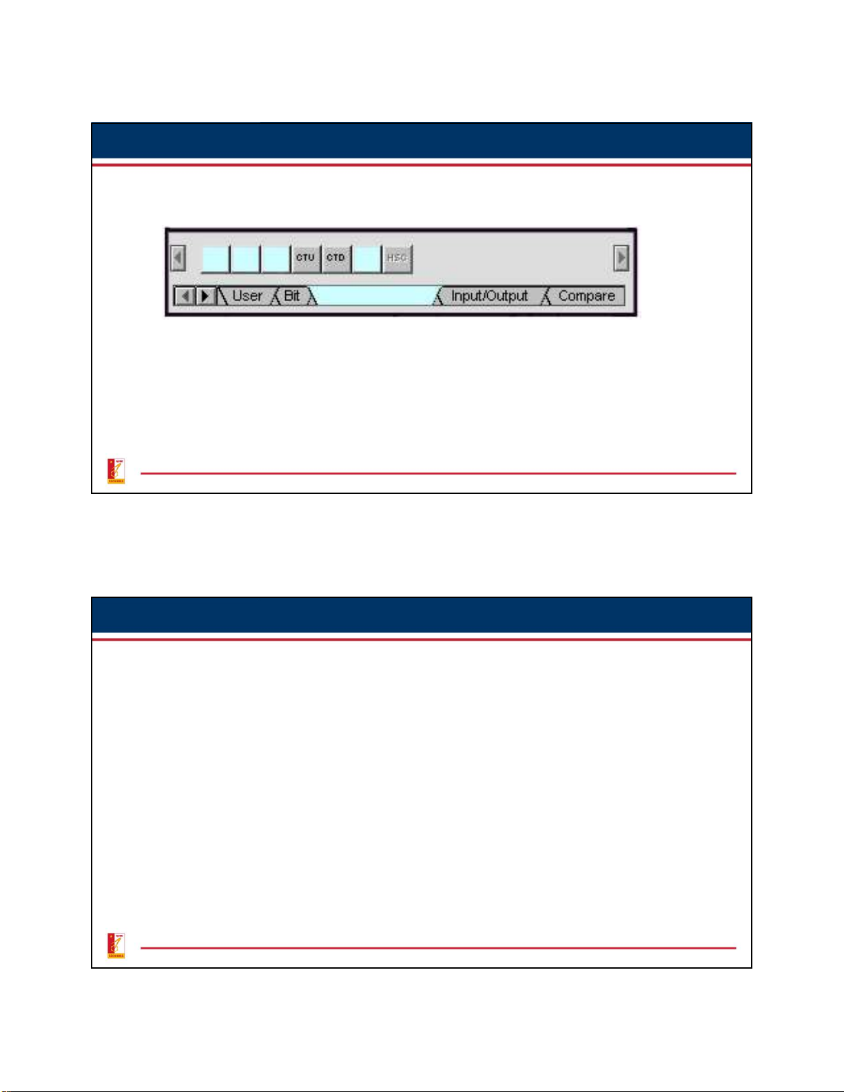
When this instruction is "true" it resets the count of the RTO counter 2 1 Timer Instructions • RSLogix Timer commands: TON TOF RTO RES 3
Quantities Associated with the Timer Instruction
• Preset Time – Represents the time duration of the timing circuit. For
example, if a time delay of 10 s is required, the timer will have a preset of 10 s.
• Accumulated Time – Represents the amount of time that has elapsed
from the moment the timing coil became energized.
• Time Base – Timers can typically be programmed with several different
time bases: 1 s, 0.1 s, and 0.01 s are typical time bases. For example, if
you enter 0.1 for the time base and 50 for the preset time the timer
would have a 5 s delay (50 x 0.1 s = 5 s). 4 2
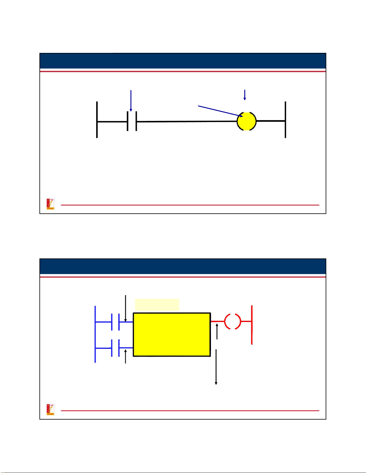
Coil-Formatted Timer Instruction Contact determines The timer assigned rung continuity an address The type of timer XXX is specified TON Preset value PR:YYY Time base 0.1 s Accumulated value AC:000
• When the timer rung has logic continuity, the timer's accumulated value increases.
• When accumulated value equals the preset value, the output is energized and and
the timed output contact associated with the output is closed. The timed contact
can be used as many times as you wish throughout the program as a NO or NC contact. 5
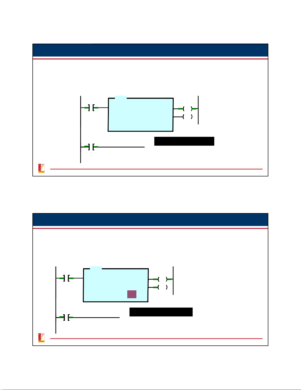
Generic Block-Formatted Timer Instruction
Control line controls the actual timing operation of the timer.
Whenever this line is true the timer will time. Timer block Preset time Time base Accumulated time Output line
Reset line resets the the timer's accumulated value to zero.
The timer continuously compares its accumulated time with its
preset time. Its output is logic 0 as long as the accumulated time is
less than the preset time. When the two become equal the output changes to logic 1. 6 3 On-Delay Timer Instruction
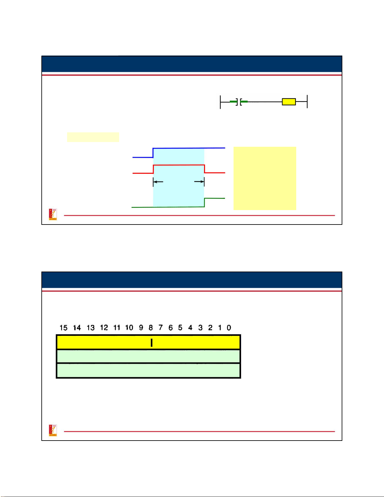
The on-delay timer operates so that, Input
when the rung containing the timer is Timer true, the timer time-out period commences. Timer Sequence True Rung condition False The timed output becomes true sometimes after the Timed period On delay timer rung becomes time duration true; hence the timer is said to have an on True delay. False Timed output bit ON OFF 7
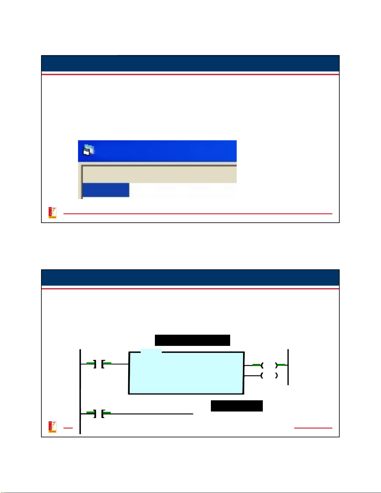
Allen-Bradley On-Delay Timer Instruction
Allen-Bradley timer takes three data table words: the control word,
preset word, and accumulated word. Word EN TT DN Internal use 0 Preset value PRE 1 Accumulated value ACC 2 Word 0 is the control word Word 1 stores the preset value
Word 2 stores the accumulated value 8 4
Allen-Bradley On-Delay Timer Instruction
Allen-Bradley timer takes three data table words: the control word,
preset word, and accumulated word.
The control word uses three control bits: Enable (EN) bit,
Timer-Timing (TT) bit and Done-Bit (DN). TIMER TABLE /EN /TT /DN T4:0 0 0 0 9
Allen-Bradley On-Delay Timer Instruction
The Enable (EN) bit is true (has a status of 1) whenever the timer
instruction is true. When the timer instruction is false, the enable bit is false (has a status of 0) Enable bit false TON TIMER ON DELAY Timer T4:0 EN T4:0 Enable bit true EN 10 5
Allen-Bradley On-Delay Timer Instruction
The Timer-Timing (TT) bit is true whenever the accumulated value of
the timer is changing, which means the timer is timing. TON TIMER ON DELAY Timer T4:0 EN Preset 50 Accumulated 10 T4:0 Timer-Timing bit true TT 11
6. Allen-Bradley On-Delay Timer Instruction
The Done-Bit (DN) changes state whenever the accumulated value
reaches the preset value. Its state depends on the type of timer being used. TON TIMER ON DELAY Timer T4:0 EN Preset 50 DN Accumulated 1 50 T4:0 Done-bit changes state DN 12 6
Allen-Bradley On-Delay Timer Instruction
The preset value (PRE) word is the set point of the timer, that is, the
value up to which the timer will time.
The accumulated value (ACC) word is the value that increments as the
timer is timing. The accumulated value will stop incrementing when its
value reaches the preset value. TIMER TABLE /EN /TT /DN .PRE .ACC T4:0 0 0 0 0 0 13
Allen-Bradley On-Delay Timer Instruction
The information to be entered includes: TON TIMER ON DELAY Timer T4:0 EN Time base 1.0 DN Preset 15 Accumulated 0
Timer number which must come from the timer file.
Time base which is expressed in seconds.
Preset value which is the length of the time delay.
Accumulated value which is normally entered as 0. 14 7
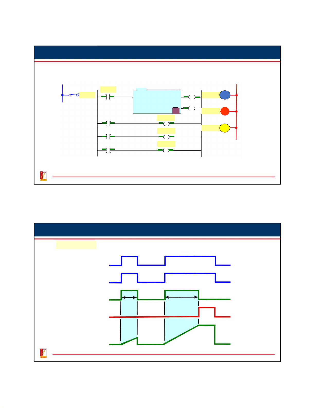
Allen-Bradley On-Delay Timer Instruction Ladder Logic Program L1 L2 Input A TON TIMER ON DELAY Input A Timer T4:0 EN Output B G Time base 1.0 Preset 10 Accumulated 10 DN 0 Output C R T4:0 Output B EN Output D Y T4:0 Output C TT T4:0 Output D DN 15
Allen-Bradley On-Delay Timer Instruction Timing Diagram On Input condition Off Timer-enable bit Timer-timing bit 4 s 10 s Timer-done bit Timer accumulated 0 value 16 8 Examples Ladder logic program Internal Inputs Stop Start Output relay L1 L2 Stop Motor M Internal Start Motor relay M Timer PR: 5 TB: 1 s Output line 17 Examples
Start-Up Warning Signal Circuit Ladder logic program Inputs Output PB1 PB2 TON Start-up TIMER ON DELAY Timer T4:0 EN PB1 Time base 1.0 T4:0 Reset Preset 10 DN Horn Accumulated 10 PB2 EN Horn T4:0 T4:0 DN EN 18 9 Examples
Timed Closed Solenoid Value Program Ladder logic program Input Output L1 L2 Switch SW_1 TON Timer On Delay SW_1 EN Timer timer_1 Valve Preset DN 12000 12000 Accumulated 0 timer_1.dn Valve 19 Examples Ladder logic program Inputs PB1 PB2 M1 Outputs OL PB1 M1 M1 PB2 OL M2 M2 PS1 PS1 OL M3 Automatic Sequential TON TIMER ON DELAY EN Control System Timer T4:0 Time base 1.0 DN Preset 15 Accumulated 10 5 T4:0 M3 DN 20 10 Off-Delay Timer Instruction
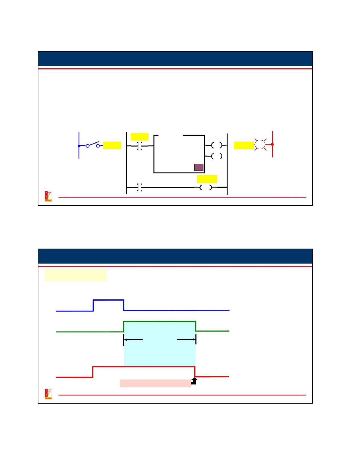
The off-delay timer (TOF) operation will keep the output energized for
a period after the rung containing the timer has gone false. Ladder logic program Input Output L1 L2 TOF S1 I:1.0/0 TIMER OFF DELAY I:1.0/0 EN O:2.0/1 PL TIMER T4:3 Time base 1.0 DN Preset 15 Accumulated 0 15 T4:3/DN O:2.0/1 21 Off-Delay Timer Instruction Timing Diagram True Input condition S1 False Timed period Off delay timed duration True (logic 1) Timed output False (logic 0) O:2.0/1
Preset value = accumulated value 22 11
Off-Delay Timer Used To Switch Motors Off Input Ladder logic program Output L1 L2 5000 10000 15000 23 Off-Delay Timer Instruction Ladder logic program Input Outputs L1 L2 5 24 12
6. Retentive On-Delay Timer Instruction
A retentive timer accumulates time whenever the device receives
power, and maintains the current time should power be removed from
the device. Once the device accumulates time equal to its preset value,
the contacts of the device change state. The retentive timer must be
intentionally reset with a separate signal for the accumulated time to be reset.
Electromechnical Retentive Timer
Once power is applied, the motor starts turning the cam. The positioning of the lobes Cam operated
determines the time it takes to activate the contact
contacts. If power is removed from the motor,
the shaft stops but does not reset. Motor-driven cam 25
6. Retentive On-Delay Timer Instruction
The PLC-programmed RETENTIVE ON-DELAY timer (RTO) operates in
the same way as the nonretentive on-delay timer (TON), with one major
exception. This is a retentive timer reset (RTR) instruction.
Unlike the TON, the RTO will hold its
accumulated value when the timer
rung goes false and will continue
timing where it left off when the timer
rung goes true again. This timer must
be accompanied by a timer reset (RES)
instruction to reset the accumulated value of the timer to zero. Same address 26 13
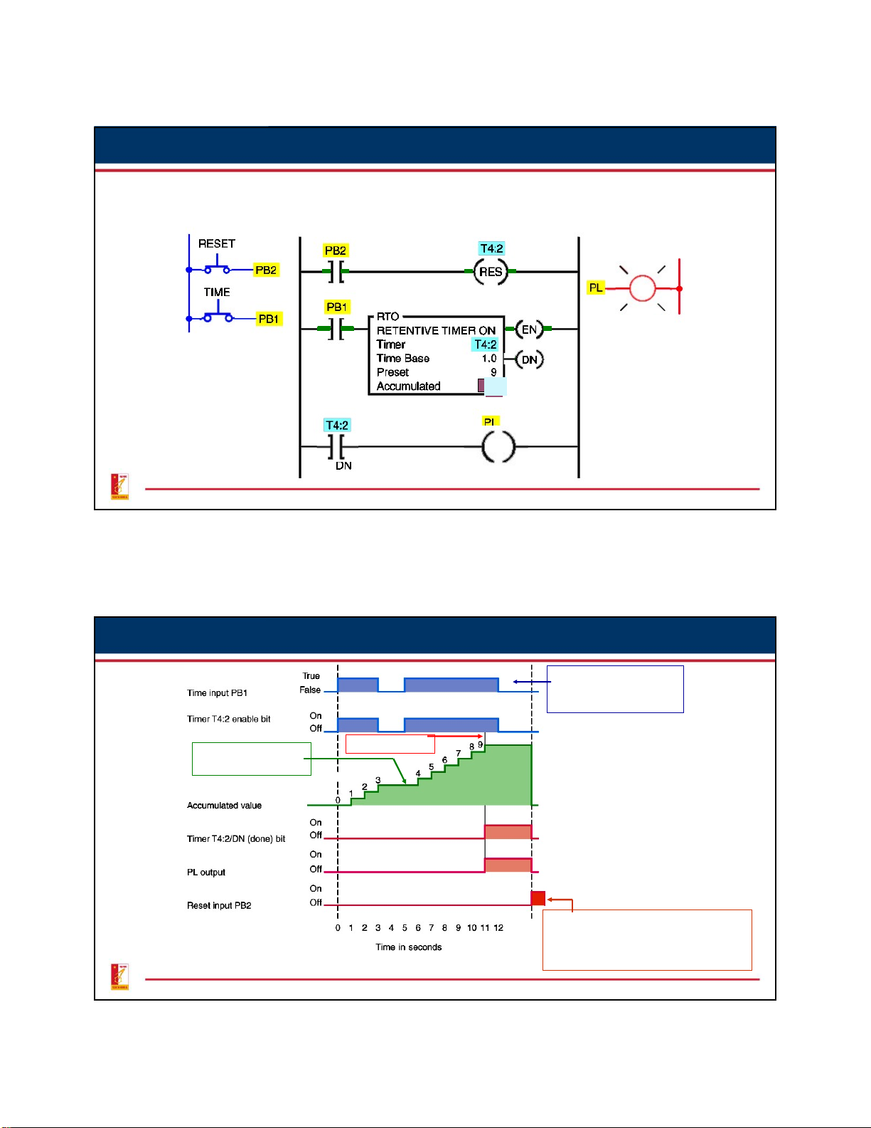
6. Retentive On-Delay Timer Instruction 3 9 0 27
6. Retentive On-Delay Timer Instruction Enable bit is reset when input pushbutton PB1 is opened Accum = Preset Accum value retained when rung goes false
When reset PB2 is closed, the T4:2/DN
bit is reset to 0. Accumulated value is
reset and held at zero until the reset pushbutton is opened. 28 14
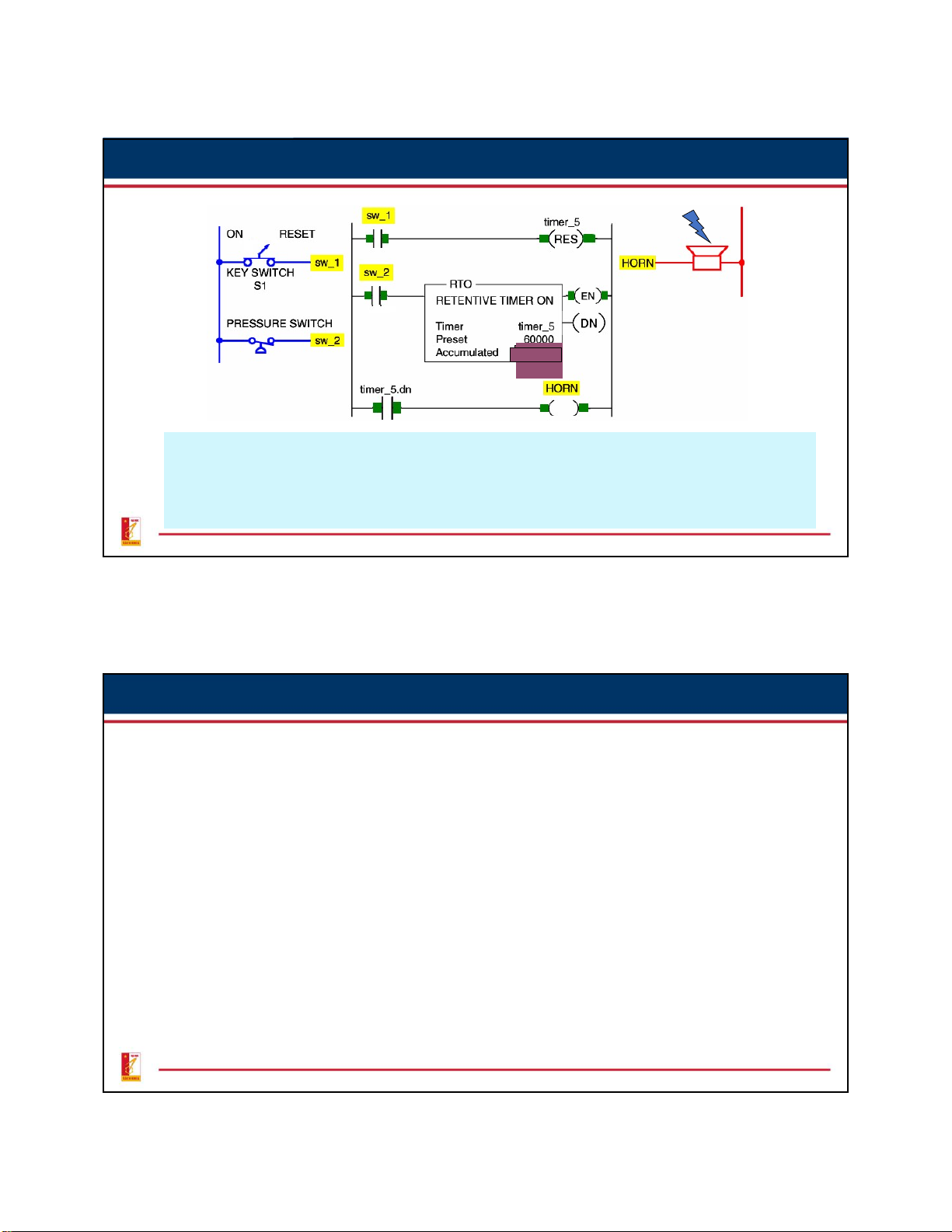
Retentive On-Delay Timer Instruction Ladder logic program L2 L1 600 0 0 0
The purpose of the RTO timer is to detect whenever a piping system has
sustained a cumulative overpressure condition of 60 s. At that point, a horn is
sounded automatically. You can silence the alarm by switching the key switch to the rest position. 29 Cascading Timers
The programming of two or more timers together is called cascading.
Timers may be interconnected, or cascaded to satisfy any required control logic. 30 15 Cascading Timers 20000 Three motors started automatically in sequence with a 20-s time delay between each motor startup. 20000 31 Cascading Timers
Cascading of Timers for Longer Time Delays 30000 12000 32 16 Cascading Timers
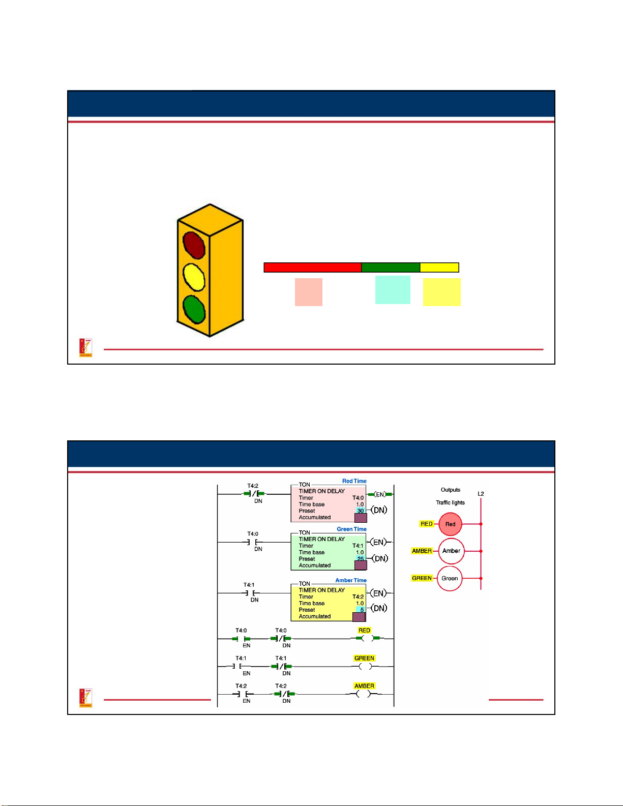
Control of Traffic Lights in One Direction
A typical application for PLC timers is the control of traffic lights.
Control of Traffic in One Direction Sequence of Operation Red Green Amber 30 s 25 s 5 s 33 Cascading Timers Control of Traffic Lights in 30 One Direction 25 5 34 17 35
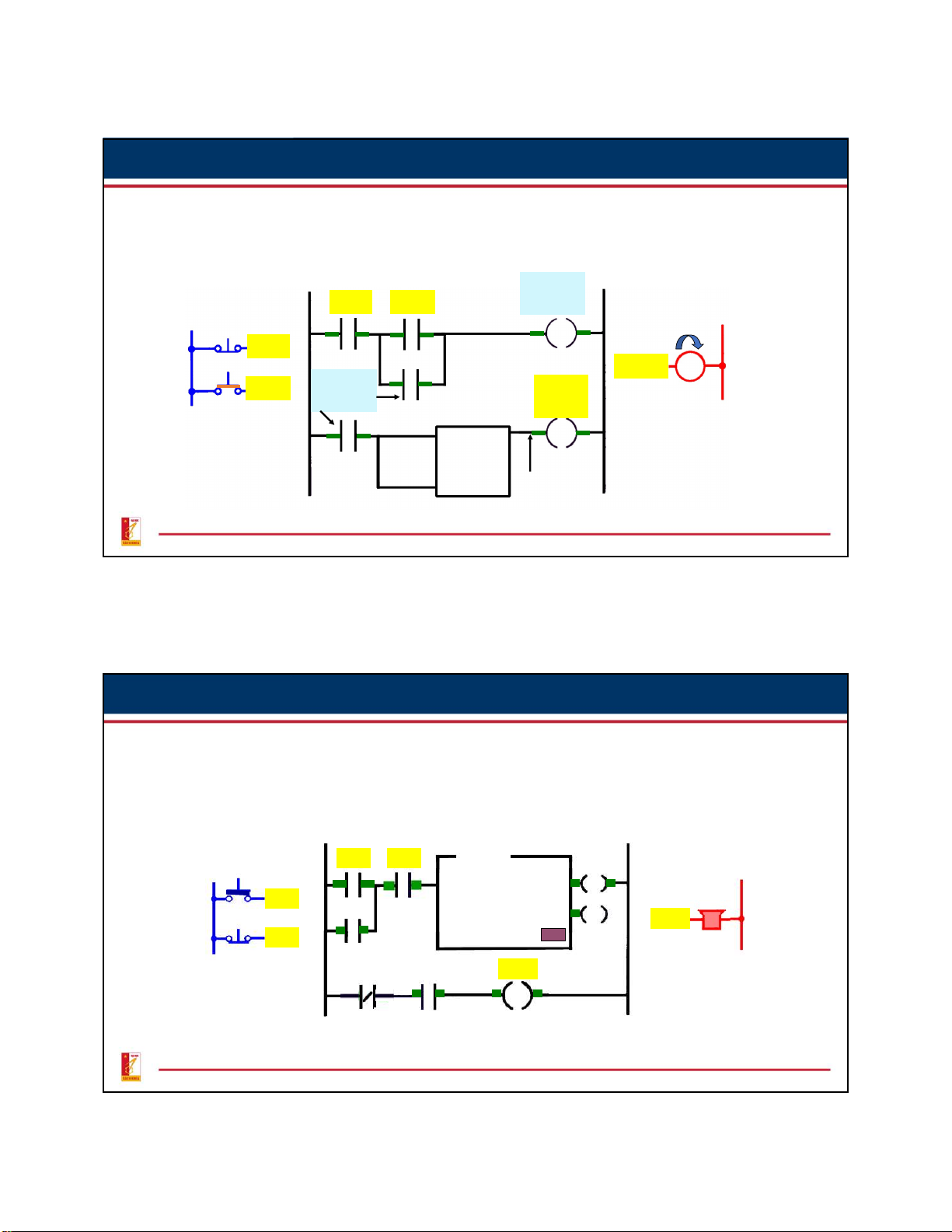
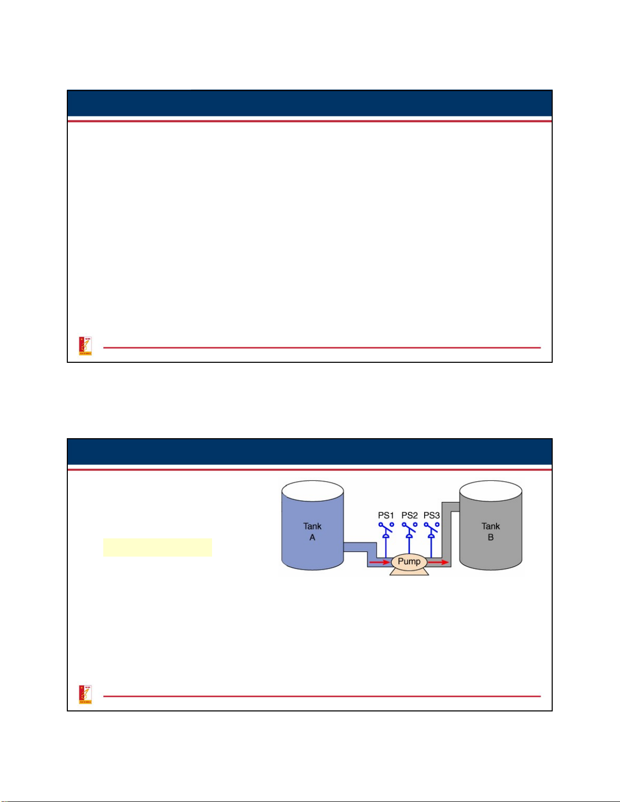
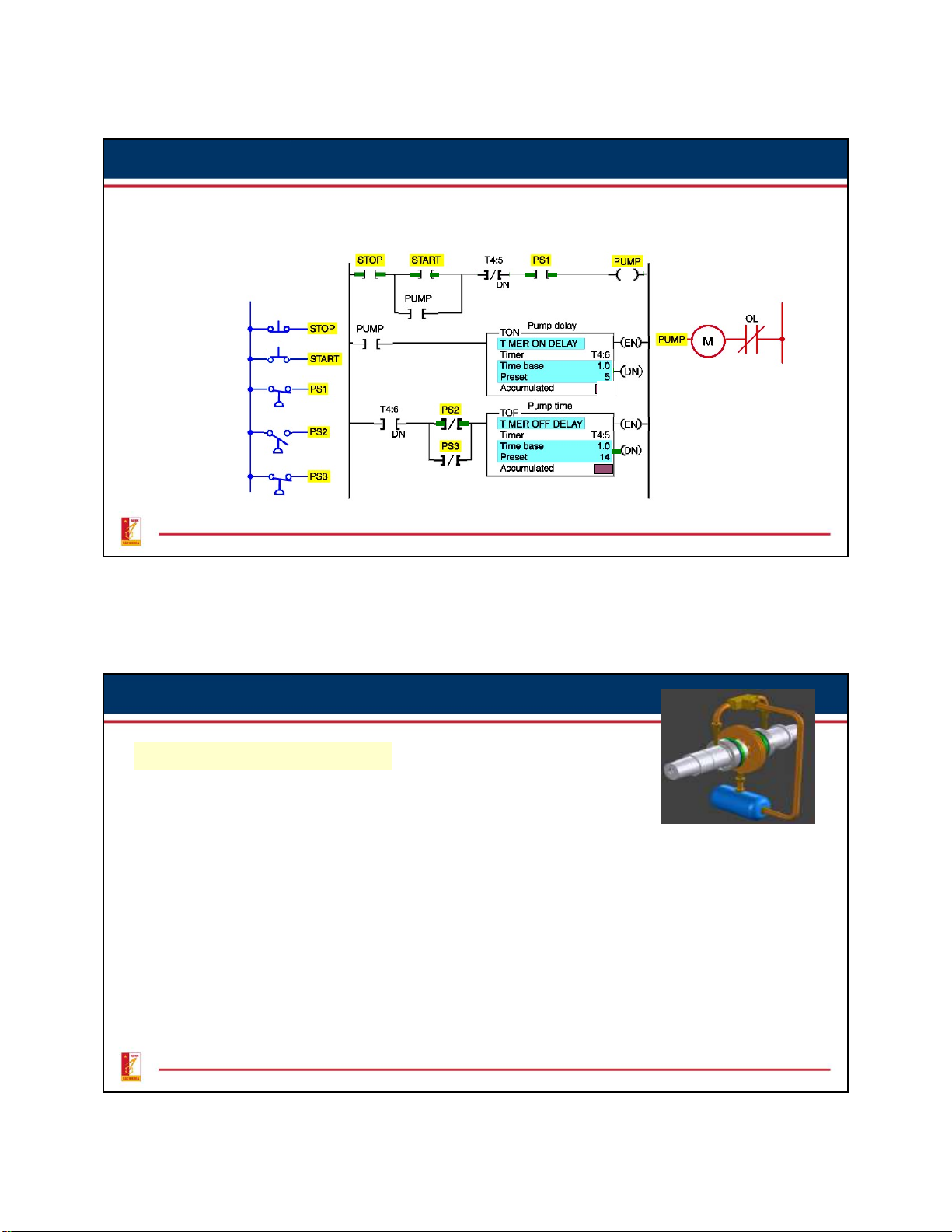
6. Example 1: Fluid Pumping Process Operation
Before starting, PS1 must be closed.
When the pump start button is pressed, the pump starts. The button can
then be released and the pump continues to operate.
When the stop button is pushed, the pump stops.
PS2 and PS3 must be closed for 5 s after the pump starts. If either PS2 or PS3
opens, the pump will shut off and will not not be able to start again for another 14 s. 36 18
6. Example 1: Fluid Pumping Process Program Ladder logic program Inputs Output L1 L2 5 0 37
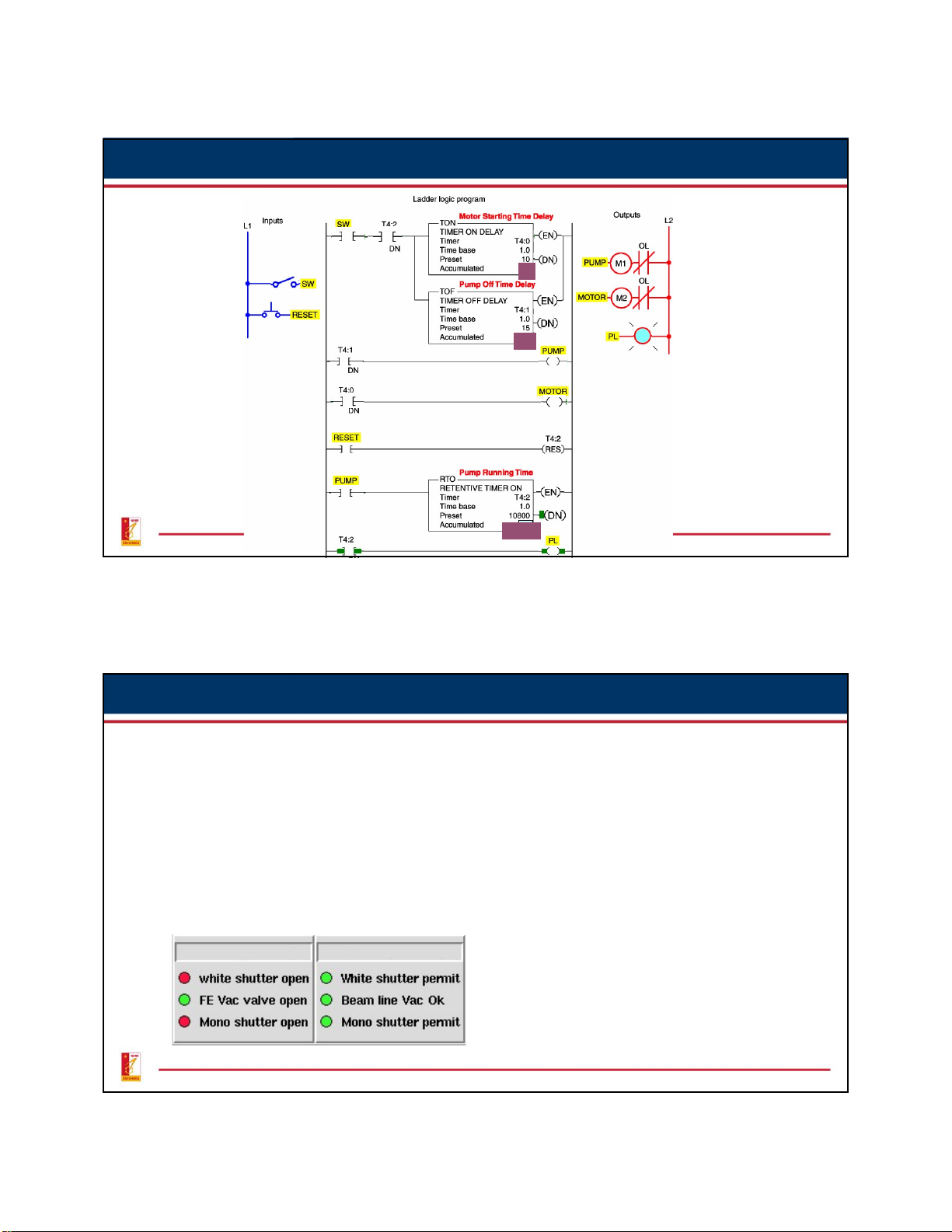
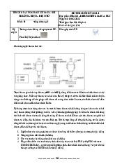
6. Example 2: Bearing Lubrication Program Sequence Of Operation •
To start the machine, the operator turns SW on.
• Before the motor shaft starts to turn, the bearings are supplied with oil by the pump for 10 s.
• The bearings also receive oil when the machine is running.
• When the operator turns SW off to stop the machine, the oil pump continues to supply oil for 15 s.
• A retentive timer is used to track the total running time of the pump. When
the total running time is 3 h, the motor is shut down and a pilot light is turned
on to indicate that the filter and oil need to be changed.
• A reset button is provided to reset the process after the filter and oil have been changed. 38 19
6. Example 2: Bearing Lubrication Program 10 0 15 10800 39
6. Examples 3: Annunciator Flasher Circuit
Two timers can be interconnected to form an oscillator circuit. The
oscillator logic is basically a timing circuit programmed to generate
periodic output pulses of any duration. They can be used as part of an
annunciator system to indicate an alarm condition. The oscillator circuit output is
programmed in series with the alarm
condition. If the alarm condition is true, the appropriate output indicating light will flash. 40 20
Tài liệu liên quan:
-

Bài giảng PLC và mạng công nghiệp PLC and industrial system môn Điều khiển logic và PLC | Đại học Bách Khoa Hà Nội
40 20 -
Báo cáo Thí nghiệm Môn Điều khiển logic và PLC | Đại học Bách Khoa Hà Nội
116 58 -
Bài tập lớn Lập trình công nghệ điều khiển nước SFC môn Điều khiển logic và PLC | Trường Đại học Bách Khoa Hà Nội
105 53 -
Đề thi cuối kỳ môn Điều khiển logic và PLC | Trường Đại học Bách Khoa Hà Nội
221 111 -
Bài giảng Giới thiệu các kiến thức môn Điều khiển logic và PLC | Trường Đại học Bách Khoa Hà Nội
112 56