Asnzs 1170.1 Supplement 12002 - Tài liệu tham khảo | Đại học Hoa Sen
Asnzs 1170.1 Supplement 12002 - Tài liệu tham khảo | Đại học Hoa Sen và thông tin bổ ích giúp sinh viên tham khảo, ôn luyện và phục vụ nhu cầu học tập của mình cụ thể là có định hướng, ôn tập, nắm vững kiến thức môn học và làm bài tốt trong những bài kiểm tra, bài tiểu luận, bài tập kết thúc học phần, từ đó học tập tốt và có kết quả
Môn: Social Psychology (PSYC 2314) 12 tài liệu
Trường: Trường Đại học Hoa Sen 5.3 K tài liệu
Tác giả:


Preview text:
AS/NZS 1170.1 Supp 1:2002 A S /N Z S 1170.1 Supp 1
AS/NZS 1170.1 Supplement 1:2002
Structural design actions—Permanent, imposed and other actions— Commentary
(Supplement to AS/NZS 1170.1:2002)
Australasia Pty Ltd on 14 Nov 2016 (Document currency not guaranteed when printed) Aurecon Accessed by AS/NZS 1170.1 Supp 1:2002
This Joint Australian/New Zealand Standard supplement was prepared by Joint T echnical
Committee BD-006, General Design Requirements and Loading on Structures. It was
approved on behalf of the Council of Standards Australia on 29 March 2002 and on behalf
of the Council of Standards New Zealand on 28 March 2002. It was published on 4 June 2002.
The following ar e represented on Committee BD -006:
Association of Consulting Engineers Australia
Australian Building Codes Board
Australian Institute of Steel Construction
Building Research Association of New Zealand
Cement and Concrete Association of Australia
CSIRO Bui lding, Construct ion and E ngineering
Cyclone Testing Station—James Cook University
Electricity Supply Association of Australia Housing Industry Association
Institution of Engineer s Australia
Institution of Professional Engineers New Ze aland Master Builders Australia
New Zealand Heavy Engineering Research Association
Steel Reinforcement Institute of Australia University of Newcastle
University of Auckland (New Zealand)
University of Canterbury (New Zealand) University of Melbourne
Kee pi ng Sta ndar ds up- to- date
Standards are living documents which reflect progress in science, technology and
systems. To maintain their currency, al Standards are periodically reviewed, and
new editions are published. Between editions, amendments may be issued.
Standards may also be withdrawn. It is important that readers assure themselves
they are using a current Standard, which should include any amendments which
may have been p ublished since the Sta ndard was p urchased.
Detai led information about joi nt Australian/New Zealand Sta ndards can be found by
visiting the Standards Australia web site at www.standards.com.au or Standards
New Zealand web site at www.standards.co.nz and looking up the relevant Standard in the on-line catalogue.
Alternatively, both organizations publish an annual printed Catalogue with full
details of all current Standards. For more frequent listings or notification of
revisions, amendments and withdrawals, Standards Australia and Standards New
Zealand offer a number of update options. For information about these services,
users should contact their respect ive national Sta ndards organizati on.
We also welcome suggestions for improvement in our Standards, and especially
encourage readers to notify us immediately of any apparent inaccuracies or
ambiguities. Please address your comments to the Chief Executive of either
Standards Australia International or Standards New Zealand at the address shown
Australasia Pty Ltd on 14 Nov 2016 (Document currency not guaranteed when printed) on the back cover. Aurecon Accessed by AS/NZS 1170.1 Supp 1:2002
AS/NZS 1170.1 Supplement 1:2002
Structural design actions—Permanent, imposed and other actions— Commentary
(Supplement to AS/NZS 1170.1:2002)
Originated in Australia as part of AS 1170.1—1989.
Originated in New Zealand as part of NZS 4203:1976.
Previous New Zealand edition NZS 4203:1992.
AS 1170.1—1989 and NZS 4203:1992 jointly revis ed, amalgamated and
redesignated in part as AS/NZS 1170.1 Supplement 1:2002.
Australasia Pty Ltd on 14 Nov 2016 (Document currency not guaranteed when printed) COPYRIGHT Aurecon
© Standards Australia/Standards New Zealand
All rights are reserved. No part of this work may be reproduced or copied in any form or by any
means, electronic or mechanical, including photocopying, wit hout the written permission of the publisher. Accessed by
Jointly published by Standards Australia International Ltd, GPO Box 5420, Sydney, NSW 2001
and Standards New Zealand, Private Bag 2439, Wellington 6020 3 ISBN 0 7337 4 472 9 AS/NZS 1170.1 Supp 1:2002 2 PREFACE
This Commentary was prepared by the Joint Standards Australia/Standards New Zealand
Committee BD-006, General Design Requirements and Loading on Structures, as a
Supplement to AS/NZS 1170.1, Structural design actions, Part 1: Permanent, imposed and
other actions. This Commentary supersedes in part AS 1170.1—1989, Minimum design
loads on structures, Part 1: Dead and live loads and load combinations and in part
NZS 4203:1 992, Code of practice for general structural design and design loadings for buildings (Vol. 2).
The Commentary provides background material and guidance to the requirements of the Standard.
The clause numbers of this Commentary are prefixed by the letter ‘C’ to distinguish them
from references to the Standard clauses to which they directly relate. Where a commentary
to certain Clauses is non -existent, it is because no e xplanation of the Clause is necessar y. ACKNOWLEDGEMENT
Standards Australia wishes to acknowledge and thank the following member who has
contributed significantl y to this Commentar y: Peter Kleeman
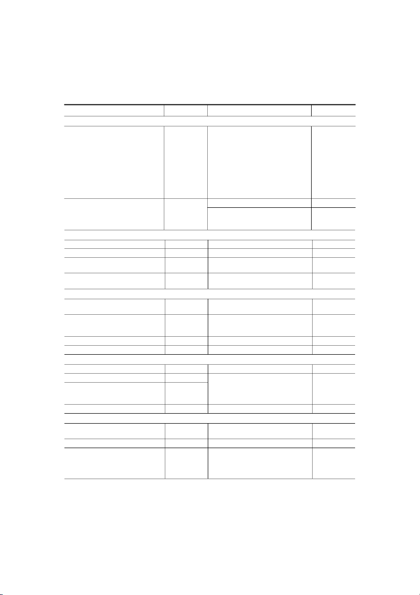
Australasia Pty Ltd on 14 Nov 2016 (Document currency not guaranteed when printed) Aurecon Accessed by 3 AS/NZS 1170.1 Supp 1:2002 CONTENTS Page SECTION C1 SCOPE AND GENERAL
C1.1 SCOPE......................................................................................................................... 4
C1.2 DETERMINATION OF DESIGN ACTIONS.............................................................. 4
C1.3 REFERENCED DOCUMENTS................................................................................... 4
C1.4 DEFINITIONS............................................................................................................. 5
C1.5 NOTATION................................................................................................................. 5 SECTION C2 PERMANENT ACTION
C2.1 GENERAL................................................................................................................... 6
C2.2 SELF-WEIGHT ........................................................................................................... 6
C2.3 PROVISION FOR PARTITIONS................................................................................ 6
C2.4 REMOVABLE LOADS............................................................................................... 6 SECTION C3 IMPOSED ACTIONS
C3.1 GENERAL................................................................................................................... 7
C3.2 CONCENTRATED ACTIONS.................................................................................... 7
C3.3 PARTIAL LOADING.................................................................................................. 7
C3.4 FLOORS...................................................................................................................... 8
C3.5 IMPOSED ACTIONS ON ROOFS, AND SUPPORTING ELEMENTS ................... 11
C3.6 BARRIERS................................................................................................................ 11
C3.7 CRANES, HOISTS, LIFTS AND RECIPROCATING MACHINERY...................... 11
C3.8 CAR PARKS ............................................................................................................. 12
C3.9 GRANDSTANDS...................................................................................................... 12
SECTION C4 LIQUID PRESSURE, GROUND WATER, RAINWATER PONDING, AND EARTH PRESSURE
C4.1 GENERAL................................................................................................................. 13
C4.2 LIQUID PRESSURE ................................................................................................. 13
C4.3 GROUND WATER ................................................................................................... 13
C4.4 RAINWATER PONDING ......................................................................................... 13
C4.5 EARTH PRESSURE.................................................................................................. 13 APPENDICES CA
UNIT WEIGHT OF MATERIALS ............................................................................ 14 CB
OTHER IMPOSED ACTIONS .................................................................................. 25
Australasia Pty Ltd on 14 Nov 2016 (Document currency not guaranteed when printed) Aurecon Accessed by AS/NZS 1170.1 Supp 1:2002 4
STANDARDS AUSTRALIA/STA NDARDS NEW ZEALAND
Australia n/New Zeal and Standar d
Struc tural desig n ac tions—Per manent, i mposed and o ther actions— Commentary
(Supple ment to AS/ NZS 1170.1:2002)
S E C T I O N C 1 S C O P E A N D G E N E R A L C1.1 SCOPE
This Commentary is intended to be read in conjunction with AS/NZS 1170.1:2002. The
commentary includes explanations of the provisions and in some cases suggests approaches
that may satisfy the intent of the Sta ndard. Co mmentary Cla uses are not mandator y. Lists of
reference s are also given for f urther readin g.
Construction actions are now specifically covered in AS/NZS 1170.0. Some comment on
construction acti vity is given under Clause C3.1. C1.2 APPLICATION
C1.3 DETERMINATION OF DESIGN ACTIONS
This Clause reflects the philosophy outlined in AS/NZS 1170.0 that design should be
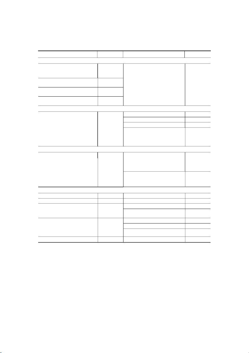
verified usin g appro priate loads . C1.4 REFERENCED DOCUMENTS
The follo wing document s are referre d to in this Co mmentary: AS 2156 Walkin g tracks 2156.1
Part 1: Classification and si gnage 2156.2 Part 2: Infrastructure desi gn 2867
Farm structures —General requir ements for structural de sign 3610 Formwor k for concr ete 4678 Earth retainin g structure s AS/NZS 1170 Structur al desi gn actions 1170.0 Part 0: General principles 1576 Scaffolding 1576.1 Part 1: General requirements NZS 4203
Code of practice for general structural design and design loadings for
buildings (Vol ume 1, Code of practic e; Volume 2, Commentary)
Australasia Pty Ltd on 14 Nov 2016 (Document currency not guaranteed when printed) BS 6399 Loads for buildin gs Aurecon 6399.1
Part 1: Code of practi ce for d ead and imposed l oads EN 1991
Basis of design a nd actio ns on str uctures (E urocode 1) Accessed by 1991-2-1
Part 2.1: Actions on str uctures—Densities , self -weight and i mposed l oads COPYRIGHT 5 AS/NZS 1170.1 Supp 1:2002 ANSI/ASCE 7-95
Minimum Desi gn Loads for Buildin gs and Other Str uctures ISO 2394
General principle s on reli ability for str uctures 9194
Bases for design of structures—Actions due to self-weight of structures, non-
structural elements an d stored materials—Densit y 10137
Bases for designs of structures—Serviceabilit y of buildings against vibration BRANZ Bulletin 227
Weights and measur es of building materials C1.5 DEFINITIONS
Definitions have been dra wn fr om ISO 2394, where appropriate. C1.6 NOTATION
Notation follo ws the guid elines laid out in ISO 3898.
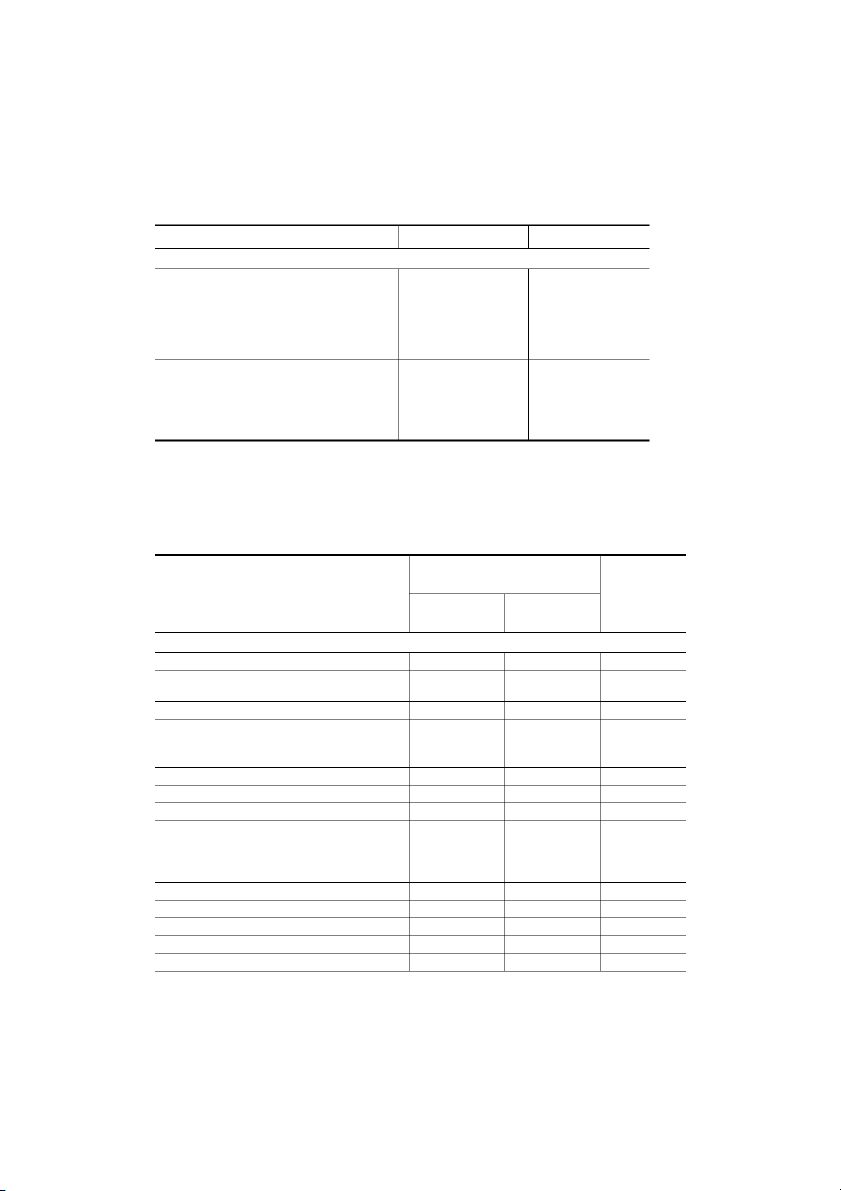
The notation used in this Commentary is as given in AS/NZS 1170.1, together with the following: F
= impact or bra king force , in ne wt ons h
= height of handrail, in milli metres l
= length bet ween handrail s upports ( verticals), in mill imetres m
= gross mass of the vehicles, in kilograms s
= mean of the lengths of the adjoinin g spans of a slab sup ported b y walls, in metres V
= velocit y of the vehicles, in metres per secon d ∆
= deceleration le ngth, i n metres
Australasia Pty Ltd on 14 Nov 2016 (Document currency not guaranteed when printed) Aurecon Accessed by COPYRIGHT AS/NZS 1170.1 Supp 1:2002 6
S E C T I O N C 2 P E R M A N E N T A C T I O N C2.1 GENERAL
The variation in magnitude of the action with time is intended to cover loads where for
most of the time the load will remain constant. For example, a tank intended t o be kept full
with suitable overflow control may be considered a permanent action. Of course the case
should als o be co nsidered where the ta nk is empti ed in the sh ort term for main tenance.
The permanent equipment may include some machinery items if it is envisaged that the
service life of the machin ery is of the same ord er as the desi gn wor king life of the str ucture. C2.2 SELF-WEIGHT
The self-weight values given in this Commentary in Appendix CA are mean values. Unit
weights of some materials are given a s follows:
(a) For i nternational purpose s in T ables CA2( A), C A2(B), and CA2( C) ( ISO 9194).
(b) For Australian con ditions in Table CA1.
(c) For New Zealand conditions, ‘Weights and measures of building materials’ may be used (BRANZ Bulletin 227). C2.3 PROVISION FOR PARTITIONS
Movable partitions are included as permanent actions, to ensure that their mass is
considered in an earthquake situation. The minimum value of 0.5 kPa is sufficient to
provide for most partitions fabricated from studs supporting glass, plywood and plasterboard. C2.4 REMOVABLE LOADS
Tanks and other receptacles and their contents, service equipment, and the like, are
considered as permanent action due to their small variability for the application of a load
factor but shoul d not be relied on for re sisting overt urning or wind uplift.
Australasia Pty Ltd on 14 Nov 2016 (Document currency not guaranteed when printed) Aurecon Accessed by COPYRIGHT 7 AS/NZS 1170.1 Supp 1:2002
S E C T I O N C 3 I M P O S E D A C T I O N S C3.1 GENERAL
The live l oads given i n this Standar d are dee med to be charact eristic loads . Where l oad data
were available ( mainly for office occupancies), the characteristic values given repr esent the
peak loads over a 50 year life with a 5 percent probability of being exceeded. Otherwise,
the characteristic loads given are the traditional loads for each occupancy and are to be regarded as mini mum values.
The imposed loads given in Table 3.1 or Appendix B are assumed to take account of the
importance and e xpected life of the struct ure. The choice of an occu pancy takes the place o
the choice of an annual probability of exceedance (as defined in Table 2.1 of
AS/NZS 1170.0). The importance and life are assumed to be part of the occupancy
description. Thus once the occupancy has been chosen, that imposed load is applicable for
design regardless of the importance level and design working life defined in AS/N ZS 1170.0.
The possibility of increased imposed actions should be considered for importance level 5 (see AS/ NZS 1170 .0).
Where the loads are not known and the type of occupancy is not covered in this Standard,
the loads shall be determi ned from—
(a) measured load inf ormation together with a probabili ty-based anal ysis; or
(b) an assess ment of the load s resultin g from— (i) assembl y of people;
(ii) accumulation of equip ment and furnishi ngs; an d (iii) storage of materials.
Actions resulting from construction are not covered in this Standard (see AS/NZS 1170.0).
Some aspects of these are treated in AS 3610 and AS/NZS 1576.1 . Close supervision of the
construction process is essential to ensure that overloading does not occur due to building
materials and equipment such as cranes or trucks. Where floor-to-floor propping is
emplo yed during construc tion, close control of the proppin g sequence shoul d be maintained
throughout the construction period and the propping system should be approved by an
engineer c ompetent in structural d esign.
For d ynamic effect s due t o human occupan cy refer t o ISO 1 0137:1992.
The distributed loads are in agreement with ISO 2633 except for parking of 2.5 t vehicles,
which is 2.5 kPa instead of 3 kPa.
The distrib uted loads are generall y equi valent to or hi gher than those given i n ISO 2103. C3.2 CONCENTRATED ACTIONS
For the determination of bendi ng moments, shear and deflection, concentr ated loads may be treated a s point l oads.
Australasia Pty Ltd on 14 Nov 2016 (Document currency not guaranteed when printed) C3.3 PARTIAL LOADING Aurecon
The Clause implies that pattern loading may have to be considered for live load. Whether
pattern loading needs to be considered or not depends on the ratio of the dead to live load
and the type of structural component. These parameters vary with the material of construction. Accessed by COPYRIGHT AS/NZS 1170.1 Supp 1:2002 8
The partial loading provision for continuous beams relaxes the pattern loading often
assumed. The relaxed provision is based on the application of Turkstra’s Rule to the
combination of independent actions that vary randomly in time, in that the maximum
lifetime value of one action is taken in combination with ‘arbitrary-point -in-time’ values of
other a ctions. The value obtained by reducing the i mposed load by its lon g-term ψ ), l factor (
provides a reasona ble estimat e of the ‘arbitrar y-point -in-t ime’ imposed load. Note that there
is no requirement to consider patterned variation of permanent loads by varying the load
factor. The factors influencing the variability of permanent loads between spans are generall y correlated.
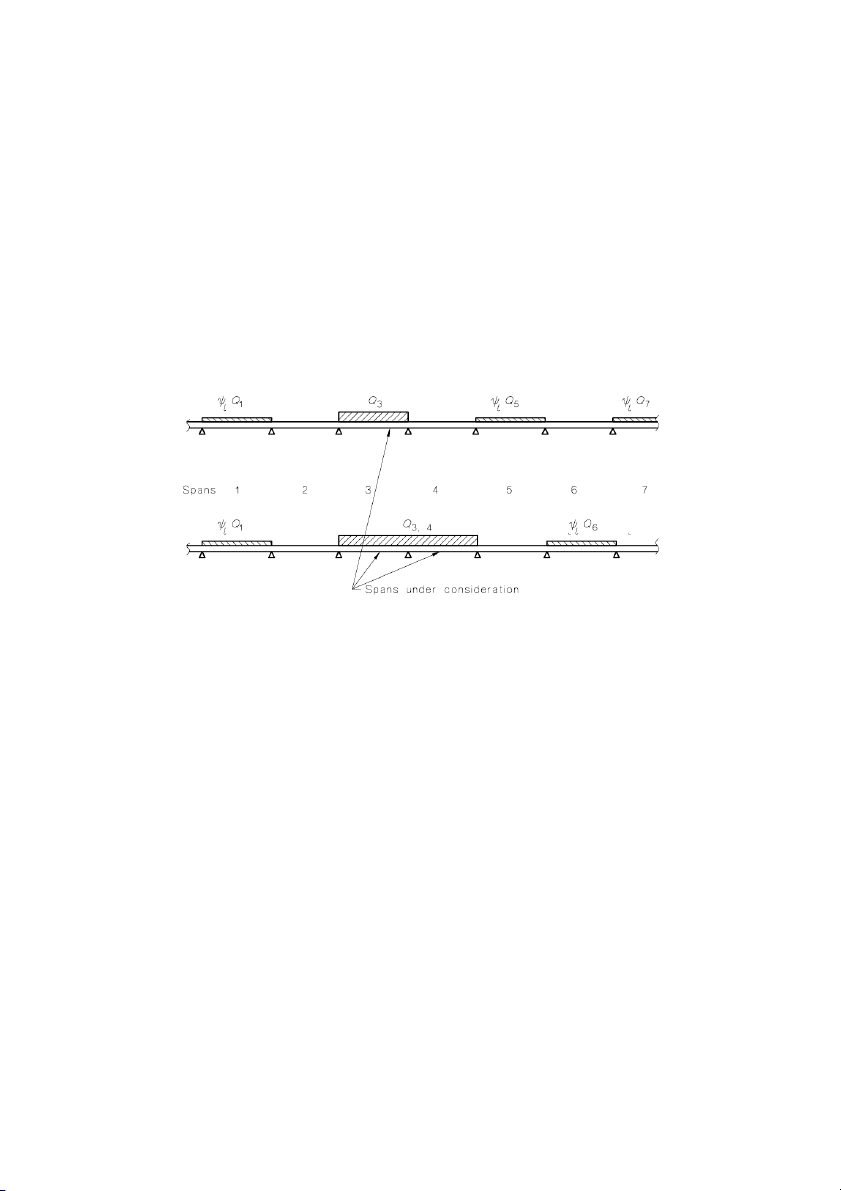
Examples of loading on continuous beams are given in Figure C3.1. Q1 to Q7 represent for each area the product of ψ ψ
a and the referen ce values given i n Table a 3 i .1 s . determined for
the tributary area of the span or spans under consideration. It is conservative to take
ψ = 1. 0, or t o take a ny or all ψ o a f = 1.0. l
FIGURE C3.1 EXAMPLES OF LOADING ON A CONTINUOUS BEAM C3.4 FLOORS C3.4.1 Imposed floor actions
It should be noted that the values given in Table 3.1 are minimum values and the designer
should determine if higher values are appropriate. For example, some supermarket floors
may need to be treated as a combination of storage areas and areas in which people may
congregate instead of as r etail areas. Table 3.1
The values given in Table 3.1 are based on values given in AS 1170.1—1989 and
NZS 4203:1992 . Where th e values were found t o be different, the differences were r esolved
by checki ng with BS 6 399.1:1996 and ENV 1991 -2-1:1996. T he revis ed format in the Table
follows that adopted in BS 6399.1, which is an expanded version of that in ENV 1991-2-1.
The examples given in the second column of the Table may be used for guidance for
occupancies not specifica lly listed.
The philosop hy of the Ta ble (based on the Europea n code) is that ea ch area of a floor woul d
Australasia Pty Ltd on 14 Nov 2016 (Document currency not guaranteed when printed)
fall into one of the activity types. Thus in order to classify an area under consideration, the
designer must consider the t ype of acti vities that occur i n that are a. Aurecon
For example, a corridor in a motel is an area where people may congregate (C), whereas the
rooms off the corridor are residential activities (A). Similarly, stairs and landings are areas
where the activity is Type C, except where the stairs and landings are wholly contained Accessed by
within a self -contained dwelling of activit y Type A. COPYRIGHT 9 AS/NZS 1170.1 Supp 1:2002
Some uses will not appear in the specific uses listed in the Table. In these cases, the
designer should choose the appropriate activity (A to G) and look for a similar specific use
or make a fresh assess ment of the li kely l oading (s ee Commentar y on Clause 3 .1).
The concentrated action for stairs and landings in self-contained dwellings has been
increase d to 2.7 kN due to a re-assess ment of i mpact force s.
‘Self-containe d dwellings’ indicat es a range fr om domestic hou sing to apartments (covering
self-contained occupancy units). The term ‘Domestic activities’ is intended to indicate
structures that fall into the definition of Class 1 buildings given in the Building Code of
Australia, or into the definition of housing as given in the New Zealand Building Code.
‘Residential acti vities’ includes buildin gs with areas where people live a nd sleep, which are
covered b y other definitio ns in the buildin g codes .
The term ‘wheeled vehicles’ refers to trolleys, cleaner’s carts, and other small vehicles up
to 300 kg gross mass, but not to cars or tru cks (see a ctivities F and G).
The value used in activity type F (2.5 kPa) was adopted from New Zealand practice and is
equivalent to the value in the British Standard. Lower values have been suggested in a
recent paper by Wen et al (Ref. 1). The Committee intend s to wait for further devel opments
before reco nsiderin g this value .
C3.4.2 Reduction of uniformly distributed imposed actions
The reduction of uniformly distributed live load is empirically based on the results of load surveys. The factor
ψa, by which some values given in Table 3.1 may be reduced, is taken
from ISO 2103 and differs only slightly in effect from the provision in AS 1170.1—1989. The area used to determine
ψa is the sum of t he trib utary areas s upported by t he member.
Note that for office occupancies, for which a considerable body of data exists, NZS 4203
and AS 1170.1 specified loads of 2.5 kPa and 3.0 kPa respectively, but the reduced loads (reduced for area using
ψa) converged to similar values for larger areas. The revised rule
maintains t hese si milar load le vels for the l arger are as.
Some linear-type structures have little capacity for t ransverse distribution of loads. It is not
intended that reduction factors should be applied to the combined areas supported by those
elements and their neighbours, unless there is capacity in the structural system to share the
peaks of imposed load between the various elements that support the loaded area. Where
transverse positive and negative moments of resistance are provided to transfer load
laterally in slabs supported on two opposite edges, partial loading of the slab with the
unreduced load will generally be critical. The critical loading case for the ultimate limit
state occurs when an area of 18 m2 (the maximum area for wh ψaic h = 1.0) is loaded and
adjacent areas are loaded with an arbitrary-point-in-time load. If a ‘one-way’ system is to
be designed by taking account of lateral load transfer, the ‘arbitrary-point-in-time’ load must be not less tha ψn Q (see AS/ NZS 1170.0) . l
Clause 4.9.2(c) of AS 1170.1—1989 allowed for a 20 percent reduction in live load
received by any column, wall or footing for which the uniformly distributed live load
exceeded 5 kPa. In the revised Table this reduction would mainly be applied to activity E
(warehousing and storage) but has been omitted. In ENV 1991-2-1 and BS 6399.1 there is
no reduction allowed for warehousing and storage areas. The omission of this allowance in
the Standard leads to some simplification in the overall process of determining imposed floor loads.
Australasia Pty Ltd on 14 Nov 2016 (Document currency not guaranteed when printed)
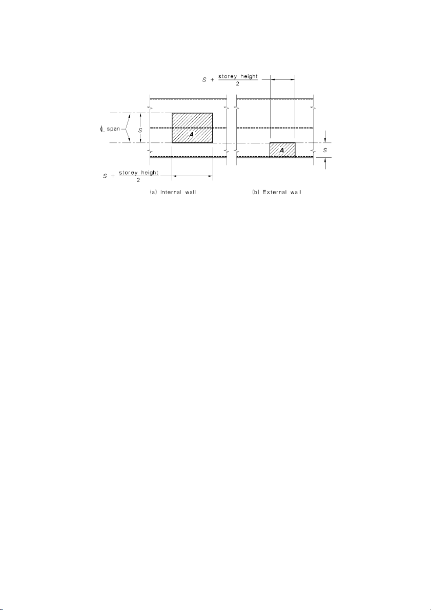
Guidance for loads on su pporting walls Aurecon
The following examples illustrate the calculation of tributary areas for imposed action on
walls that s upport a flo or (see Clause 3.4.2). Accessed by COPYRIGHT 11 AS/NZS 1170.1 Supp 1:2002
FIGURE C3.4 LONG W ALLS W ITH SMALL OPENINGS OR WITHOUT OPENINGS
(Principal reinforcement in one direction only)
C3.5 IMPOSED ACTIONS ON ROOFS, AND SUPPORTING ELEMENTS C3.5.1 Roofs
Roof Category R1 is intended to cover situations where people may gain unauthorized
access through their own efforts to a roof not intended for such use. The lower load of 1.0
allows for greater difficulty in gaining access compared to the value of 1.5 where access
may be facilitated by adjacent windows, balconies or other awnings. An example is a street
awnin g on a multistore y building with openable windows.
It is not expected that people would walk on glass or other transparent or translucent
materials such as plastic sheeting. Therefore, allowance has been made for transparent
surfaces to be treated as an area where supports (e.g., boards) would be placed over the
surface when access is necessar y (usuall y for mai ntenance) .
The limit of 0.25 kPa in Table 3.2 is intended to cover situations not covered elsewhere in
the loading Standards, such as stacking of materials for maintenance or for local accumulations of hail.
C3.5.2 Roof supporting trusses, ceilings, skylights and similar structures
The provision regarding concentrated loads supported by roof trusses or other primary roof
members is intended to provide for a common situation for which specific requirements are generall y lacking. C3.6 BARRIERS
The ne w Table reflects th e provisions gi ven in BS 6 399.1 and ENV 1 991-2-1.
For serviceability, the deflection of handrails may be considered acceptable if they do not
exceed h/6 0 + l/240 (hori zontal deflection).
Australasia Pty Ltd on 14 Nov 2016 (Document currency not guaranteed when printed)
C3.7 CRANES, HOISTS, LIFTS AND RECIPROCATING MACHINERY C3.7.1 General Aurecon
In general, the designer should refer to the referenced Standards. The alternative factors
given in Clau se 3 .7 are si milar to those given i n ANSI/AS CE 7 -95. Accessed by COPYRIGHT AS/NZS 1170.1 Supp 1:2002 12
While in most cases the load effects need to be ascertained only for immediate supporting
members (e.g., corbels supporting crane rails, beams supporting lift machinery), the load
path needs to be pursued further in cases where the operating weight of machinery is the
primary load on a structure. It should be appreciated, however, that treating these dynamic
loads as st atic loads will often predict deflectio ns th at are unrealisticall y lar ge. C3.7.2 Vertical actions
C3.7.3 Horizontal actions on crane rails C3.8 CAR PARKS
The value s given in the Standard are base d on th e force fr om one vehicle onl y.
Braking and horizontal impact forces arising from the movement of vehicles may be calculate d as follows: = 2 mV F ∆ 2 . . . C3.8 where
F = i mpact or brakin g force, i n newt ons
m = gross mass of the vehicles, in kilogra ms
V = velocit y of the vehicl es, i n metres per se cond
∆ = decelerati on len gth, in me tres
In calculating the braking force, ∆ is taken as the braking distance, and in calculating the
impact forc e on a barrier, ∆ is taken as t he sum of the deflecti on of t he vehicle and b arrier.
The loads given f or car p ark barriers are bas ed on t he follo wing:
(a) 1500 kg at 2 m/s and 0.1 m crumple zone.
(b) 2000 kg at 6 m/s and 0 .15 m crumple zone.
(c) 2000 kg at 2 m/s and 0.1 m crumple zone.
Wheel stops should not be relied upon to stop a vehicle impacting a barrier except in
normal use. The shape and desi gn of wheel stops varies and i nformation is not available on
their effe ctiveness i n stop ping or reducin g the s peed of vehicles. C3.9 GRANDSTANDS
Clause 4 .10 of AS 1170.1—1989 INCREASE OF UNIFORMLY DISTRIBUTED LIVE LOAD ON RESTRICTED AREAS
This Clause from the previous Australian edition of the Standard prescribed an increased
uniformly distributed load on areas less than 3 m2. There is no similar provision in
BS 6399.1, ENV 1991-2-1, ANSI/ASCE 7-95 nor was there in NZS 4203:1992. The
provision has been removed for simplicity, as for small areas the maximum moments are
generally reached when the specified concentrated loads are applied. Whilst shear in
cantilevers supporting restricted areas may have been controlled by the increased
Australasia Pty Ltd on 14 Nov 2016 (Document currency not guaranteed when printed)
distribute d load, the relaxation of this re quirement i s not co nsidered si gnifican t. REFERENCES Aurecon 1
WEN, Y.K., YEO, G.L., Design live loads for Passenger Cars Parking Garages,
Journal of struct ural e ngineerin g, A. S.C. E., Mar ch 2001, p p.280 -289. Accessed by COPYRIGHT 13 AS/NZS 1170.1 Supp 1:2002
S E C T I O N C 4 L I Q U I D P R E S S U R E , G R O U N D
W A T E R , R A I N W A T E R P O N D I N G , M O V E M E N T
E F F E C T S A N D E A R T H P R E S S U R E C4.1 GENERAL C4.2 LIQUID PRESSURE C4.3 GROUND WATER
It is unlikely that information will be available on the level of ground water for different
annual probabilities of exceeda nce. T herefore t he 1 in 50 val ue is given a s the default value .
Assuming the level to be at ground level is a conservative assumption for most situations.
The presence or absence of ground water should be considered for the purposes of
combinations, as the absence of hydrostatic water pressure may produce more critical conditions t han its presence.
Where flooding, heavy rains, variations in sea level or similar can occur, the additional
action of the water above ground level may need to be considere d.
It may be necessary to make other provisions to safeguard against the occurrence of
excessive pressure or flooding. Tidal charts should give reliable regular tide levels (e.g.,
spring tides). Added height may be required to account for storm surge. For soil-retaining
structures and foundations, effects of ground water need to be considered in conjunction
with the effects of soil lo ads and with soil stren gth. C4.4 RAINWATER PONDING
Where secondary drainage such as overflow outlets from gutters is provided, the ‘depth of
water that may collect’ may be assumed to be limited to the resulting maximum feasible
depth given collection rat e versus overflow rate. C4.5 EARTH PRESSURE
AS 4678 provides methods for determining Fe,u for both ultimate and serviceability limit
states. These values are appropriate for use with the combinations of actions given in
AS/NZS 1 170.0. Where other methods of deter mining the earth pressures are used, different load factors are requir ed.
Australasia Pty Ltd on 14 Nov 2016 (Document currency not guaranteed when printed) Aurecon Accessed by COPYRIGHT AS/NZS 1170.1 Supp 1:2002 14 APPENDIX CA UNIT WEIGHT OF MATERIALS (Informative)
The unit weights given in the Standard have been expressed in the for m of weights for ease
of calc ulation. Only th e most freq uently us ed materials ar e co vered.
Further data is given in Tables CA1 and CA2. Table CA1 includes values of bulk densities drawn from AS 2 867—1986.
Tables CA2(A), CA2(B) and CA2(C) are drawn from ISO 9194. As the values given in
ISO 9194 are deterministic in nature and represent the range of national mean values
submitted for the drafting of that Standard, they do not necessarily reflect Australian and
New Zealand conditio ns. The densities are given in kg/m3 and the pressures in N/ m2.
Where Tables CA2(A), CA2(B) and CA2(C) give only one density value for a material (or
soil), this means that the corresponding nominal values do not normally differ significantly
in different countries (up to ±5 percent) and the indicated mean value is the average of the
nominal values. The range of two values of densities given in the annexes for one material
indicates that the mean va lues of de nsities for different co untries vary betwee n the i ndicated
ones. The values for angles of repose are similarly expressed except that the ranges are of
the or der of ±30 perce nt, therefore, values should be considered as approxi mations only. TABLE CA1
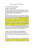
BULK DENSITIES OF AGRICULTURAL MATERIALS Minimum desig n bulk
Particulars of agricultural material density kg/ m3 Grains Barley 670 Oats 550 Rice 550 Wheat 850 Rye 700 Sorghum 730 Maize 800 Oil seeds Safflower 550 Canola 750 Linseed 0 Cotton seed 400 Sunflower 400 Soy bean 800 Other field crops Lima beans (dry) 700 Soy beans 750
Australasia Pty Ltd on 14 Nov 2016 (Document currency not guaranteed when printed) Field peas 750 Peanuts (unshelled) 300 Mai ze cob s 450 Aurecon (continued) Accessed by COPYRIGHT 15 AS/NZS 1170.1 Supp 1:2002 TABLE CA1 (continued) Minimum desig n bulk
Particulars of agricultural material density kg/ m3
Hay—rectangular and big round bales 200
Silage (moisture content 70 percent wet basis): Stored up to 2 m de ep 550 Stored more than 2 m deep 650 Fruit and vegetables Apples 600 Beans 400 Carro ts 650 Cherries 800 Onions (dry) 750 Potatoes 650 Eggs in cases 200 Tobacco 550 Wool, shearing shed bales 300
Fertilizer (bulk), superphosphate 1200
Manure (faeces and urine mixed) 1000 Feeds Lu cern me al, deh ydrat ed 350 Lucern pellets 700 Brewers grains, dried 250 Brewers grains, wet 1000 Bonemeal 850 Fish meal 550 Meat meal 600 Linseed oil meal 600 Soy bean oil meal 600 Salt 1150 Wheat, bran 250 Pelleted ration 600 Ground ration 550
Australasia Pty Ltd on 14 Nov 2016 (Document currency not guaranteed when printed) Aurecon Accessed by COPYRIGHT AS/NZS 1170.1 Supp 1:2002 16 TABLE CA2(A)
DENSITY OF MATERIALS AS GIVEN IN ISO 9194—REPRESENTATIVE VALUES
OF THE DENSITIES OF STRUCTURAL AND NON-STRUCTURAL ELEMENTS Material Density kg/m3 Material Density kg/m3
Wood and substitutes (air-dried, about 15 percent moisture content) (see Note 1) Hardwoods Softwoods Beech tree (Fagus sylvatica) 680 Black pin e (Pinus laricio) 570 Oak tree (Quercus) 690
Lar ch tre e ( Lar ix d eci du a) 550
Perp endicu lar oa k (Quer cus robu r) 640 Norway spruce (Picea) 430
Brazil ian ro sewood (Dalb ergia Spruce fir (Pinus eccelsa) 380 to 440 nigra) 800 Scotch pine (Pinus silvestris) 490 Turkey oak (Quercus cerris) 640 to 770 White willow (Salix alba) 330 Yew tree (Taxus baccata) 640 Giant poplar (Populus alba) 410
Trembling poplar (Populus tremula) 450 Ocume (Ocume) 410 Fibreboard Extruded chipboard 500 to 750 hard 900 to 1 000 Coreboard 450 to 650 medium-hard 600 to 850 porous insulatin g 250 to 400 Concrete (see Note 2)
Blast furnace foam slag concrete
1 600 to 1 900 Perlite concrete 350 to 700 Aerated and gas concrete 600 to 1 500 Tuff concrete 1 400 to 1 600 Expanded clay gravel concrete 700 to 1 700
Lightwei ght aggregate concrete using1 600 to 1 850
sintered pulverized fuel ash aggregates Heat insulating gas concr ete 300 to 900
Heat insulating pe arlite brick and 260 pipeshell Aggregates and fillers Sand 1 550
Crushed slag stone of 5 to 40 mm grain 1 500 size
Sand gravel of 0 to 40 mm grain size 1 700
Pulverized fuel ash (pozzolan) for use a 8 s 0 0a to 1 050
cementitious compon ent in concrete (bulk density) Gravel
1 500 to 1 600 Blast furnace foam slag 1 700 Aerated silicate 1 000 Blast furnace slag, granulated 1 200 Mortars Lime mortar 1 200 to 1 800 Fireclay mortar 1 900 Lime cement mort ar 1 750 to 2 000 Pearlite mortar
Cement mortar (with 2.5 MPa o r greater 2 100 lime 340 compressive strength) gypsum 370 cement 440 Rock floor mortar 1 600 Bitumen mortar with river sand 1 700
B uil ding br ic ks an d bl ocks
Tuff blo ck with 5 MPa compres sive 1 100 Lime-sand bric k 1 700 strength Glass brick, double-walled 870 to 1 100 Cob brick, adobe 1 600 Acid resistant br ick 2 000 Gas silicate bloc k
Australasia Pty Ltd on 14 Nov 2016 (Document currency not guaranteed when printed)
with 2 MP a compr essi ve str ength 500
with 5 MP a compr essi ve str ength 700 Aurecon
with 7, 5 MPa compressive str ength 900 (continued) Accessed by COPYRIGHT 17 AS/NZS 1170.1 Supp 1:2002 TABLE CA2(A) (continued) Material Density kg/m3 Material Density kg/m3 Brick masonry
Wal ls mad e from bri ck wi th hol es or 1 15 to 1 450 Gas silicate, medium-sized buildin g block
ceramic blocks (depending on the type
with 1.5 to 2.5 MP a compressive 600 to 800 of brick or blocks us ed) strength
Glass brick, double-walled (in cement 2 000
with 2.5 to 5 MP a compressiv e 800 to 1 100 mortar) strength
Glass brick, coupled on on e side (in 870 with 5 to 10 MPa compre ssive 900 to 1 300 cement mortar) strength
Acid resistan t brick (in bitu men mortar 1 900 with 10 to 20 MP a compressive 1 000 to 1 600 strength Natural building stones Sedimentary rocks Magmatic plutonic ro cks 2 650 to 3 000 sandstone 2 700 Magmatic vulcanit es 2 500 to 2 850 marl 2 300 Volcanic tuffs 1 400 to 2 000 porous limestone
1 700 to 2 200 Transformed rocks fresh -wat er limes tone 2 400 compact limestone 2 650 to 2 800 clay slate 2 600 dolomite 2 800 marble 2 700 Masonry from natural stones Rocks o f in itial se tting Transfor med roc ks
basalt malph ir, diorit, gabbro 3 000 gneiss, granulite 3 000 basalt la va 2 400 slate 2 800 diabase 2 900 serpentine 2 700 granite, syngenit, porphyt 2 800 Sedimentary rocks trachyt 2 600
graywacke, sandstone, puddingstone 2 700 volcanic tuff 2 000
Covering and other building material Tar (pitch) 1 100 to 1 400 Rubber floor 1 800 Cellulose acetate pan el 1 300 Plastic tile 1 100 Soft coverin g brick Polyamide (e.g. diamid) 1 100 holed 1 350
Polyester resin, without filler 1 350 solid 1 600 Epo xy r esin Po lyet hyl ene 930 withou t filler 1 150 Polyisobutylene-base board 1 350 with mineral mat ter 2 000 Polymethylacrylate 1 150 with fibre glass 1 800 Fenoplast 1 500 Polypropylene 930 NOTES:
1 The body density of the wood should be increased by 120 kg/m3 where in a state saturated with water and by
80 kg/m3 in the case of a structure standing outdoors and not protected against atmosph eric humidity.
2 The values given do not include steel reinforcement. Density should be that as given for the appropriate concrete
increased by 100 kg/ m3 where the reinforcement percentage is 1.25 or less. Appropriate adjustments should be mad e
Australasia Pty Ltd on 14 Nov 2016 (Document currency not guaranteed when printed)
for co ncret e reinfor ced to hi gher mass es. Aurecon Accessed by COPYRIGHT AS/NZS 1170.1 Supp 1:2002 18 TABLE CA2(B)
DENSITY OF MATERIALS AS GIVEN IN ISO 9194—REPRESENTATIVE
VALUES IN TERMS OF SURFACE PRESSURE AND WEIGHT FO R ROOF ING MA TERI ALS Material Surface pressure N/m2 Surface density kg/m2
Roof shells, roofings (see Note) Metal plate roofings
Double-welt copper roof covering, 0.6 mm 60 6 Alu miniu m she et roo fing 6 mm thick 20 2 7 mm thick 25 2.5
Lead-plate roofing, 2 mm thick, soldered 240 24 Oth er p lat e ro ofin gs
Soft plastic roofing, 1 mm thick Bitumenized bo ard roofing 90 9 2 layer, nailed 80 8
3 layer with stuck gravel scattering 250 25
NOTE: The values do not include the fixing and suppo rting structur es. TABLE CA2(C)
DENSITY OF MATERIALS AS GIVEN IN ISO 9194—REPRESENTATIVE
VALUES OF DENSITIES AND ANGLES OF REPOSE FOR STORED MATERIALS Density (see Note 1) kg/m3 Angle of Material repose, Natural heap Stack or pile degrees (see Note 2) (see Note 3)
Buildi ng and construction materials Boulder clay — 2 100 —
Brick sand, brick hardcore, brick chippings, moist 1 500 — 25 to 40 earth Cement 1 100 to 1 200 1 300 to 1 600 18 to 28 Clay fluor fine, d ry 1 100 — — he avy, air-d ried 1 600 — Cork grit — 60 — Coke ash 750 — 25 Crushed foamed slag 900 — 35 Expanded clay gravel light 250 — 30 to 35 medium 400 — 30 to 35 heavy 550 — 30 to 35 Fibreglass — 160 to 180 —
Australasia Pty Ltd on 14 Nov 2016 (Document currency not guaranteed when printed)
Foamed scoria, crushed, moist earth 1 100 — 35 Glass wool — 100 to 110 —
Gravel and dry sand or moist earth 1 800 — 30 to 36 Aurecon Heat-insulating perlit e brick — 260 — (continued) Accessed by COPYRIGHT
Tài liệu liên quan:
-
Tiểu luận giứa kì: Nên duy trì hay chấm dứt bất bình đẳng giới ?Giải tỏa áp lực lên người đàn ông trong gia đình
232 116 -
2021 Adolescent Behaviors and Experiences Survey - Tài liệu tham khảo | Đại học Hoa Sen
235 118 -
Bài Tập Thống Kê Chương 5 - Chọn mẫu - Phỏng đinh trị số dân số (K47 2022) - Tài liệu tham khảo | Đại học Hoa Sen
320 160 -
Bài Tập Thống Kê Chương 6 - Lập và kiểm nghiệm GT TKê (K47 2022) - Tài liệu tham khảo | Đại học Hoa Sen
252 126 -
Bài Tập Thống Kê Chương 7 - KNGT với 2 mẫu độc lập (K47 2022) - Tài liệu tham khảo | Đại học Hoa Sen
292 146