Chapter I Introduction To Machine Tools môn Máy và Hệ thống điều khiển số | Trường Đại học Sư phạm Kỹ thuật Thành phố Hồ Chí Minh
Chapter I Introduction To Machine Tools môn Máy và Hệ thống điều khiển số | Trường Đại học Sư phạm Kỹ thuật Thành phố Hồ Chí Minh
Môn: Máy và hệ thống điều khiển số 6 tài liệu
Trường: Trường Đại học Sư phạm Kỹ thuật Thành phố Hồ Chí Minh 4.4 K tài liệu
Tác giả:


Preview text:
Chapter I INTRODUCTION to MACHINE TOOLS
I. Machine Tool Classification & Designation
II. Motions in Machine Tools
III. Kinematic Structures
IV. Setting-up Machine Tools
V. Transmissions in Machine Tools 1
I. Machine Tool Classification & Designation 1. Classification
a. Depending upon the processing operation: Lathes Milling machines Shapers Drilling machines Grinding machines …
b. Depending upon the degree of specialization:
General-purpose (universal) machine tools Single-purpose machine tools Specialized machine tools 2
I. Machine Tool Classification & Designation 1. Classification
c. Depending upon the accuracy classes:
Machine tools of standard accuracy
Machine tools of above-standard accuracy
Machine tools of high accuracy
High-precision or Master machine tools
d. Depending upon the weight of machine tools: Light-weight (up to 1 ton) Medium-weight (up to 10 tons)
Medium-Heavy weight (from 10 to 30 tons)
Heavy-weight (from 30 to 100 tons)
Extra-Heavy weight (over 100 tons) 3
I. Machine Tool Classification & Designation 2. Designation
a. According to Russian Standard:
The first digit: indicates the main group of machine tools
The second digit: indicates the type of machine tools
The last one or two digits: represents one of the most
important dimensions of the machine tool
The letter indicates the modernized version of the machine tool
Ex: 16K20, 6H12, 2A135, 7350 …
b. According to VN Standard: The first digit is changed by one of
the following letters T, P, K, B, M … Ex: T620, P12, K135, B350 … 4
II. Motions in Machine Tools
1. Formative motions (CĐ tạo hình)
+ Depending upon manufacturing technology:
a. Primary cutting motion (CĐ chính)
b. Feed motion(s) (CĐ chạy dao) c. Other motions (if any)
+ Depending upon the functional relation of motions:
a. Simple motions (Elementary motions) b. Complex motions c. Simple and complex motions
2. Auxiliary motions (CĐ phụ)
Auxiliary motions include the advance of the cutting tool to the
surface of the work and its withdrawal, motions of changing 5 cutting tools …
II. Motions in Machine Tools 6
II. Motions in Machine Tools 7
II. Motions in Machine Tools 8
II. Motions in Machine Tools 9
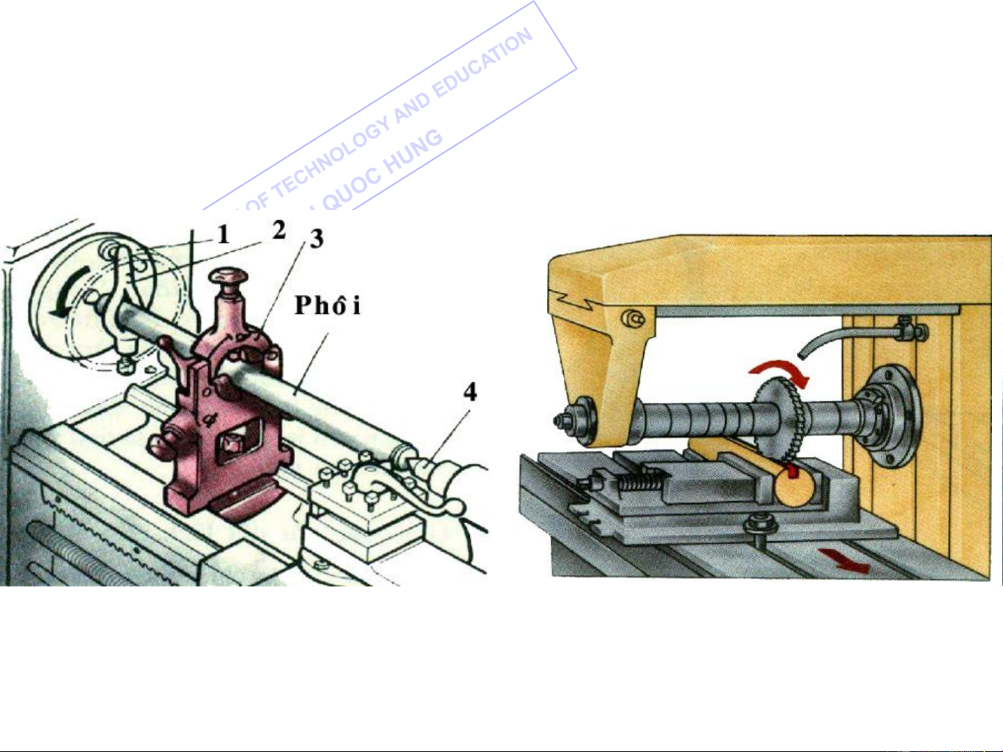
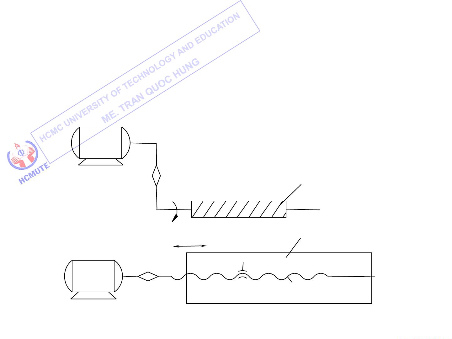
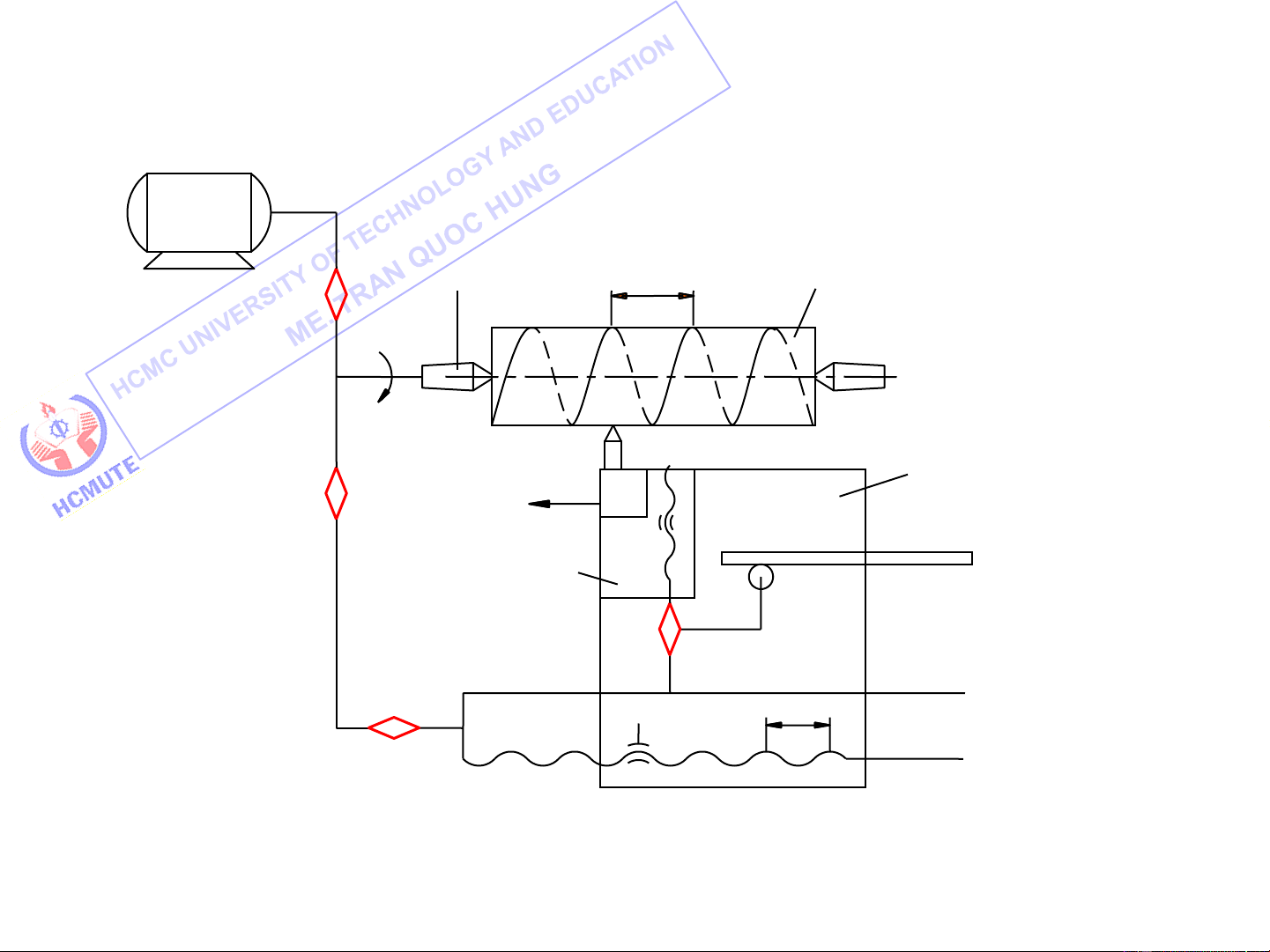
II. Motions in Machine Tools
Depending upon manufacturing technology:
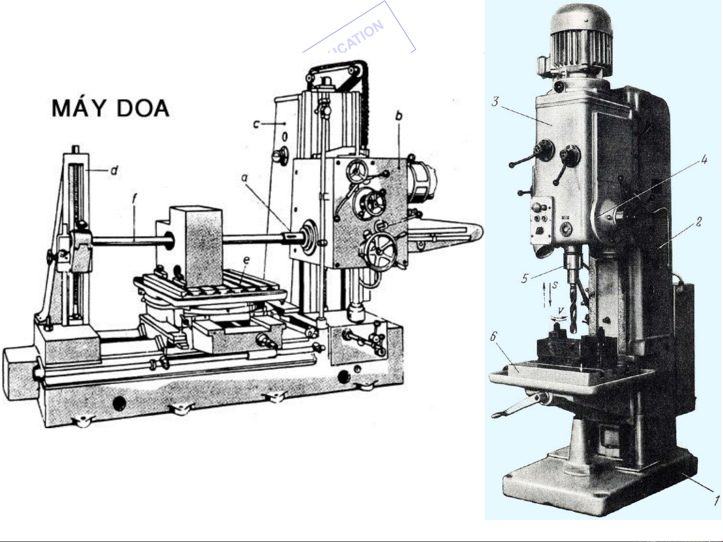
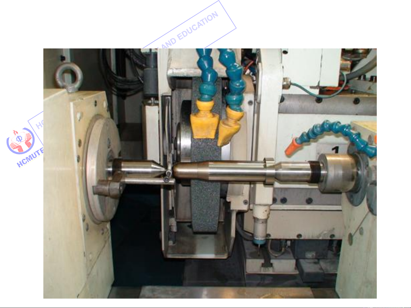
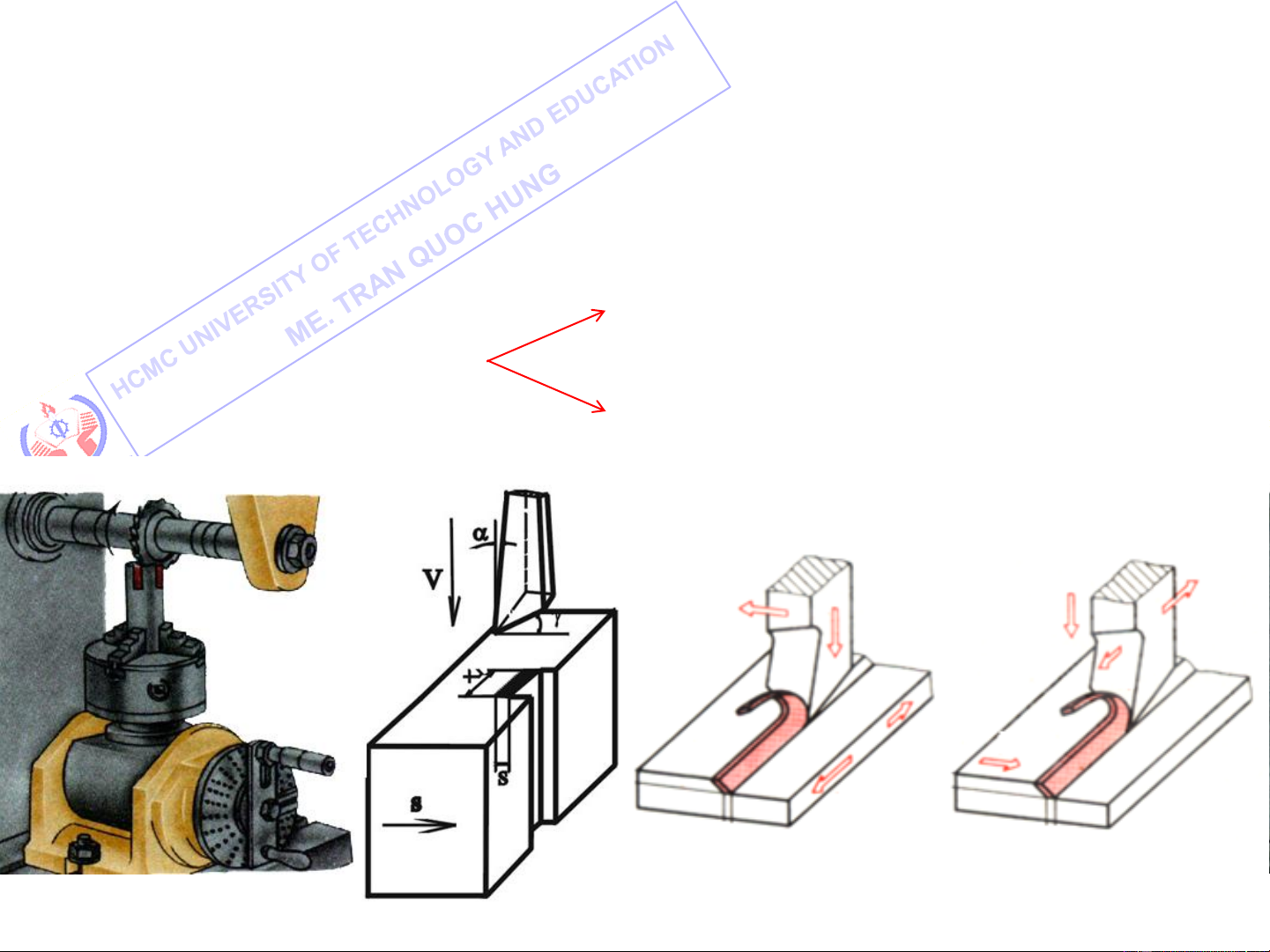
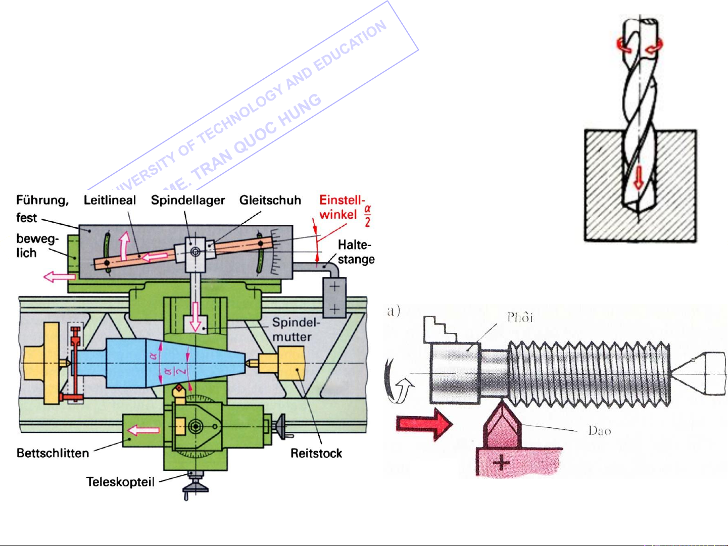
a. The primary cutting motion: provides the cutting speed
between the blank and the cutting tool. a rotary motion
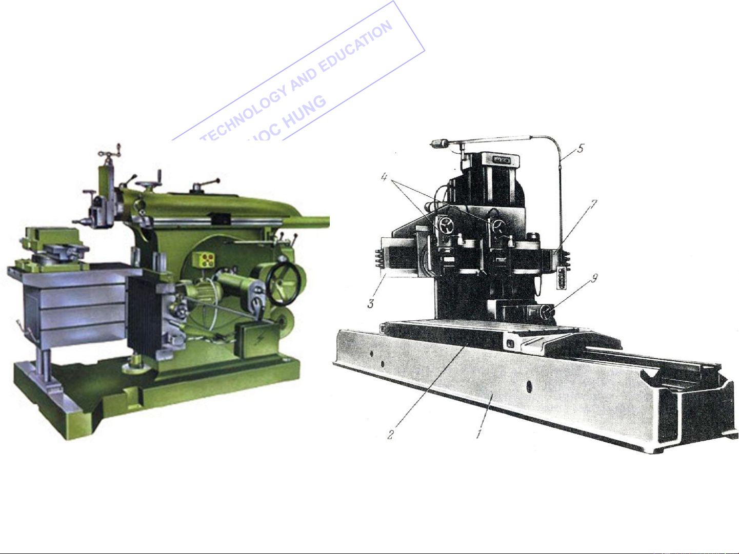
The primary cutting motion may be a reciprocating motion a one-way straight-line motion 10
II. Motions in Machine Tools
Depending upon manufacturing technology:
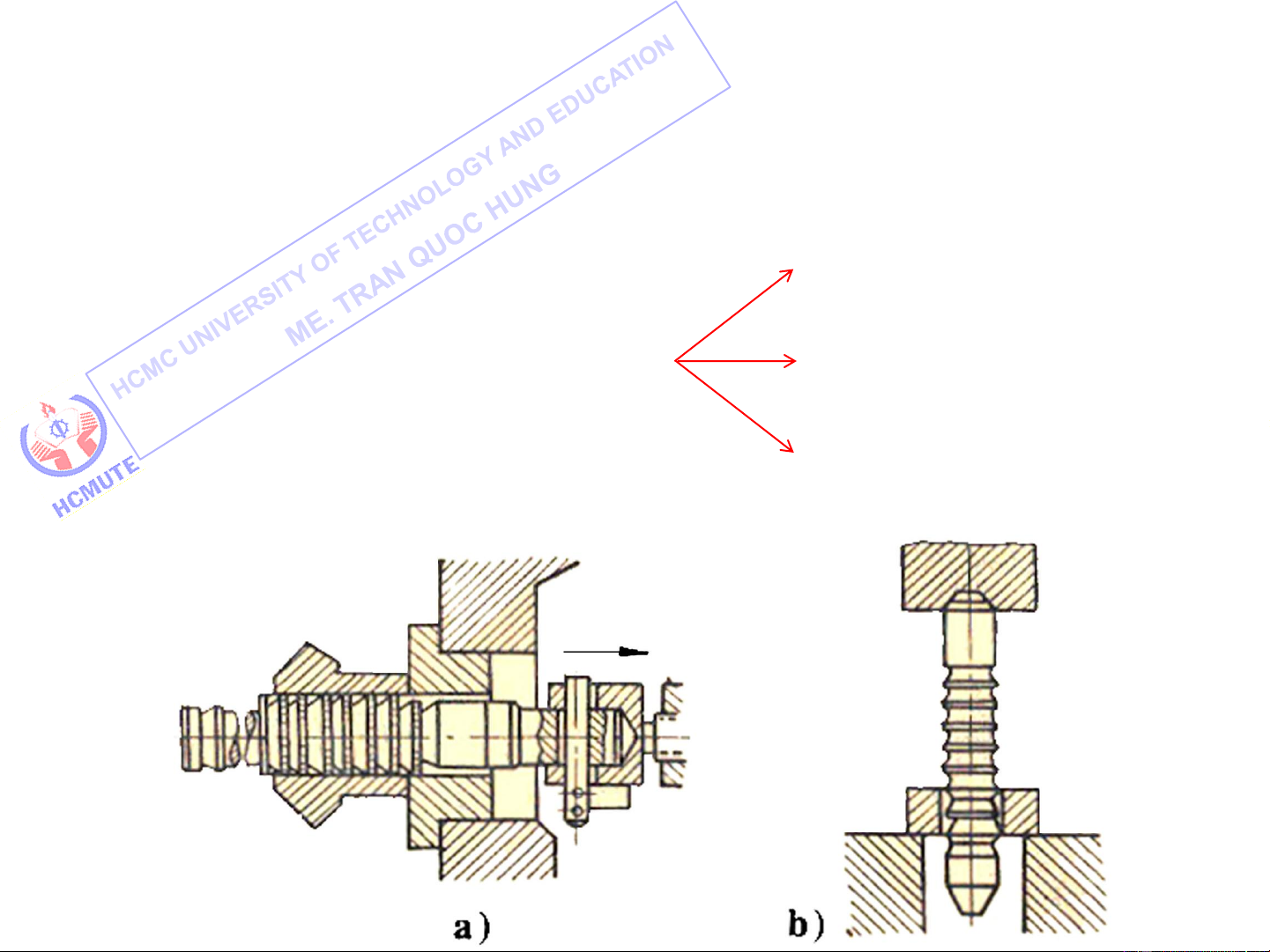
b. The feed motion : enables the cutting process to be extended
to the whole surface on the work. a straight-line motion The feed motion may be
a intermittent straight-line motion 11
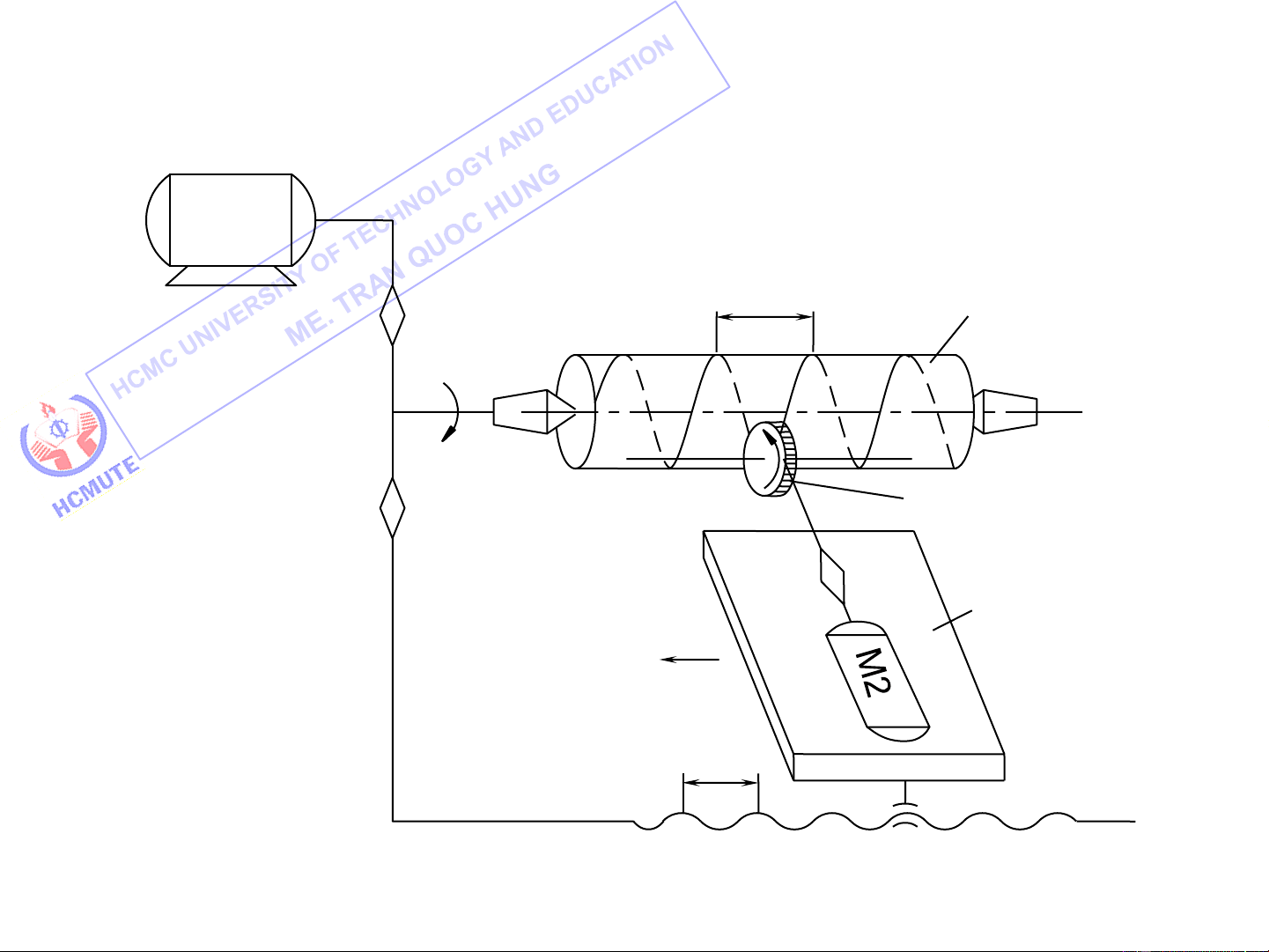
II. Motions in Machine Tools
Depending upon the functional relation of motions:
a. Simple motions (Elementary motions) b. Complex motions 12
II. Motions in Machine Tools c. Simple and complex motions 13
III. Kinematic Structures Classification:
Simple Kinematic Structures
Complex Kinematic Structures
Combined Kinematic Structures M1 iv Tool V s Table is M2 tx
Kinematic Structure of an Universal Milling Machine 14
III. Kinematic Structures
Complex Kinematic Structures Motor Blank Spindle i tp v V s Carriage itt Cross t slide xn ixd Feed rod tx Lead screw is
Kinematic Structure of an Engine lathe 15
III. Kinematic Structures
Combined Kinematic Structures M1 tp Blank iv V1 V2 V Tool is 1 Table s tx
Kinematic Structure of a Thread Milling machine 16
IV. Setting-up Machine Tools
Setting-up Machine Tools is based on the following three steps:
Kinematic chains can be make up.
Kinematic balance equations can be written. Setup formulas are determined. Kinematic chains include:
Cutting speed chain: for the primary cutting motion.
Feed chain: for the feed motion.
Indexing chain : for the indexing motion. … 17
IV. Setting-up Machine Tools
Cutting speed chain: to serve to set up the primary cutting motion.
Kinematic balance equation of the primary cutting motion: nđc . i = n v tc
nđc : motor revolution (vg/ph) n : spindle revolution (vg/ph) tc
i : transmission ratio of the speed gearbox v 18
IV. Setting-up Machine Tools
Feed chain : to serve to set up the feed motion.
Kinematic balance equation of the feed motion : t = t x p 1vtc . i . i . i ñc tt s i mZ = sd xd t = s xn n
where iđc : transmission ratio of the reversing drive
i : transmission ratio of the change gears tt
i : transmission ratio of the feed gearbox s i
: transmission ratio of the apron xd
t , t : pitch of the lead screw and the feed screw (mm) x xn
t : pitch of the thread being cut (mm) p
m, Z : module and tooth of the rack pinion
s , s : longitudinal and cross feed rates (mm/vg) d n 19
V. Transmissions in Machine Tools
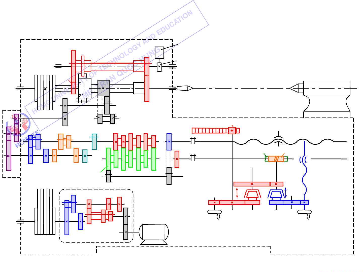
1. Gearing diagrams Oil pump 63 17 V Cam 200 55 27 IV VI VII 22 L1 55 VIII 58 a IX 35 35 c 22 m = 2 14 39 39 39 24 48 52 24 36 39 26 26 26 t = 6 mm Lead screw x XI XV b 39 45 k = 2 Feed rod X XII XIV 26 d 27 30 21 27 m 39 39 39 52 52 52 52 5 m XIII 60 24 = 26 t xn 50 39 L L3 47 2 40 27 33 55 47 II 15 13 25 38 XVI XVII XVIII I 58 III 31 38 45 N = 4,5 KW n = 1445 v/p 48 42 200 71
Gearing diagram of the model T616 engine lathe 20
Tài liệu liên quan:
-

phân tích bài thơ việt bắc khổ 2
1 1 -
Giáo trình môn Máy và Hệ thống điều khiển số | Trường Đại học Sư phạm Kỹ thuật Thành phố Hồ Chí Minh
23 12 -
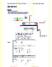
Bài tập PLC | Trường Đại học Sư phạm Kỹ thuật Thành phố Hồ Chí Minh
34 17 -
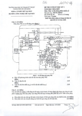
Đề thi cuối kỳ Môn Máy và hệ thống điều khiển số | Đại học Sư phạm Kỹ thuật Thành phố Hồ Chí Minh
171 86