Chapter 6 Electrically actuated directional control valves môn Pneumatic & Hydraulic Technology
Chapter 6 Electrically actuated directional control valves môn Pneumatic & Hydraulic Technology . Tài liệu giúp bạn tham khảo, ôn tập và đạt kết quả cao. Mời đọc đón xem!
Môn: Tài liệu Tổng hợp 3.6 K tài liệu
Trường: Tài liệu khác 3.9 K tài liệu
Tác giả:


Preview text:
Pneumatic & Hydraulic Technology Chapter 6 Electrically actuated
directional control valves
Instructor: Phan Thi Thu Thuy
Instructor: Phan Thi Thu Thuy Email: thuyptt@hcmute.edu.vn Mobile Phone: H 0 ig 90 her 3.13 E 0 ngi
.454 neering Education Alliance Program Contents Video 4 1
Components in the electrical signal control section 2
Spring return 2/2 way electrically actuated valve 3
Spring return 3/2 way electrically actuated valve 4
Electrically actuated pilot controlled 5/2 way valve 5
Pilot controlled 5/2 way double solenoid valve 6
Design eletro-pneumatic circuit 2 Objectives
1. Be able to draw symbol of 4 types of components
in the electrical signal control section within 5
minutes after attending the lecture.
2. Be able to draw and demonstrate 100% correctly
the working principle of 4 types of electrically
actuated directional control valves in the lecture.
3. Be able to choose the appropriate electrically
actuated directional valves and design basic
circuit to control the given cylinder in a appointed
particular case with 100% correctly. 3
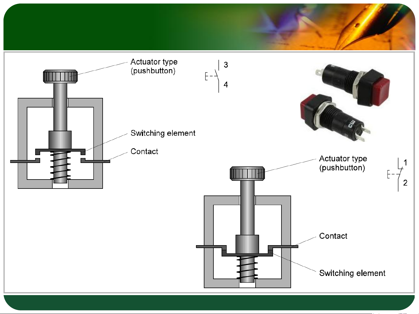
Push button – NO/NC Contact Normally Open Contact Normally Closed Contact 4
Push button - Changeover Contact Changeover Contact 5
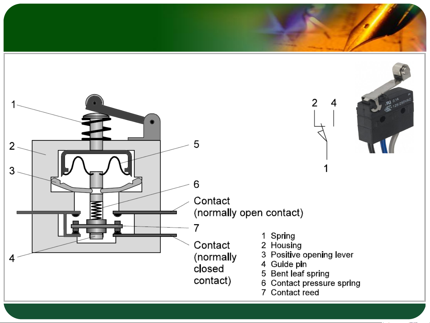
Sensor for measuring displacement Mechanical Limit switch 6
Sensor for measuring displacement
❖ Công tắc hành trình bao gồm các tiếp điểm bằng điện,
tác động bằng cơ khí. Các tiếp điểm này mở ra hay
đóng khi các xy lanh đạt tới vị trí nào đó (giới hạn), và
tác động lên công tắc.
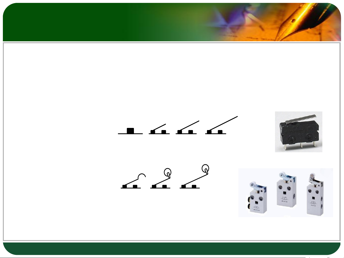
Có một số dạng thường sử dụng như sau: (a) (b) (c) (d) (e) (f) (g)
- Dạng chốt/ bản lề (ngắn/dài)
- Dạng bản lề giả con (a) (b) (c) (d) (e) (f) (g) lăn (ngắn/dài) 7
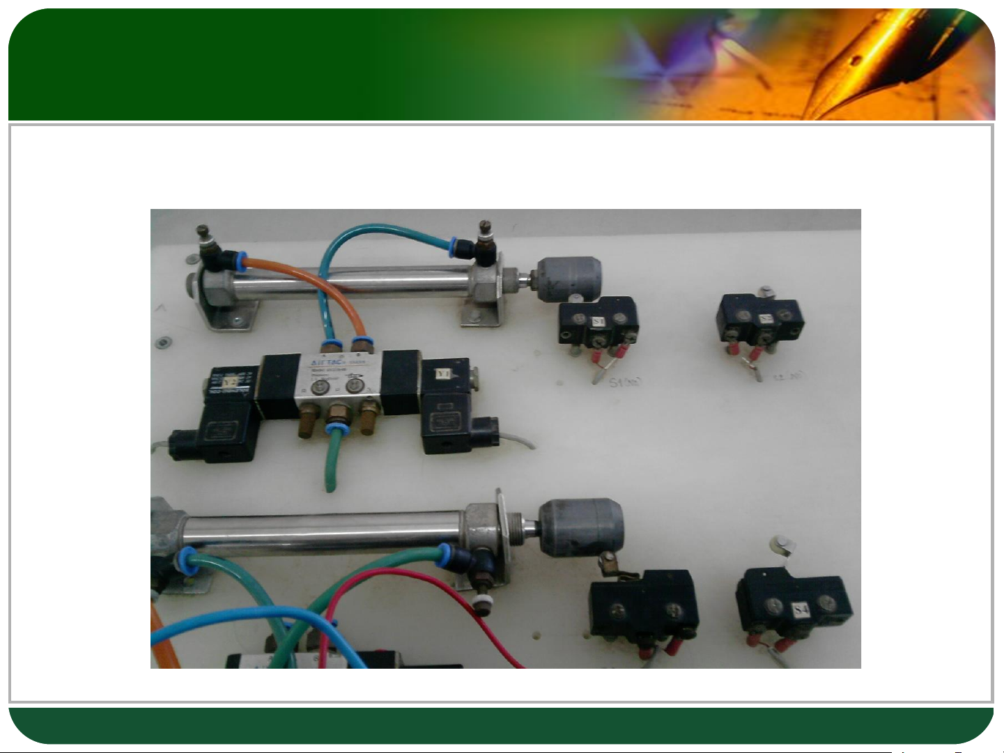
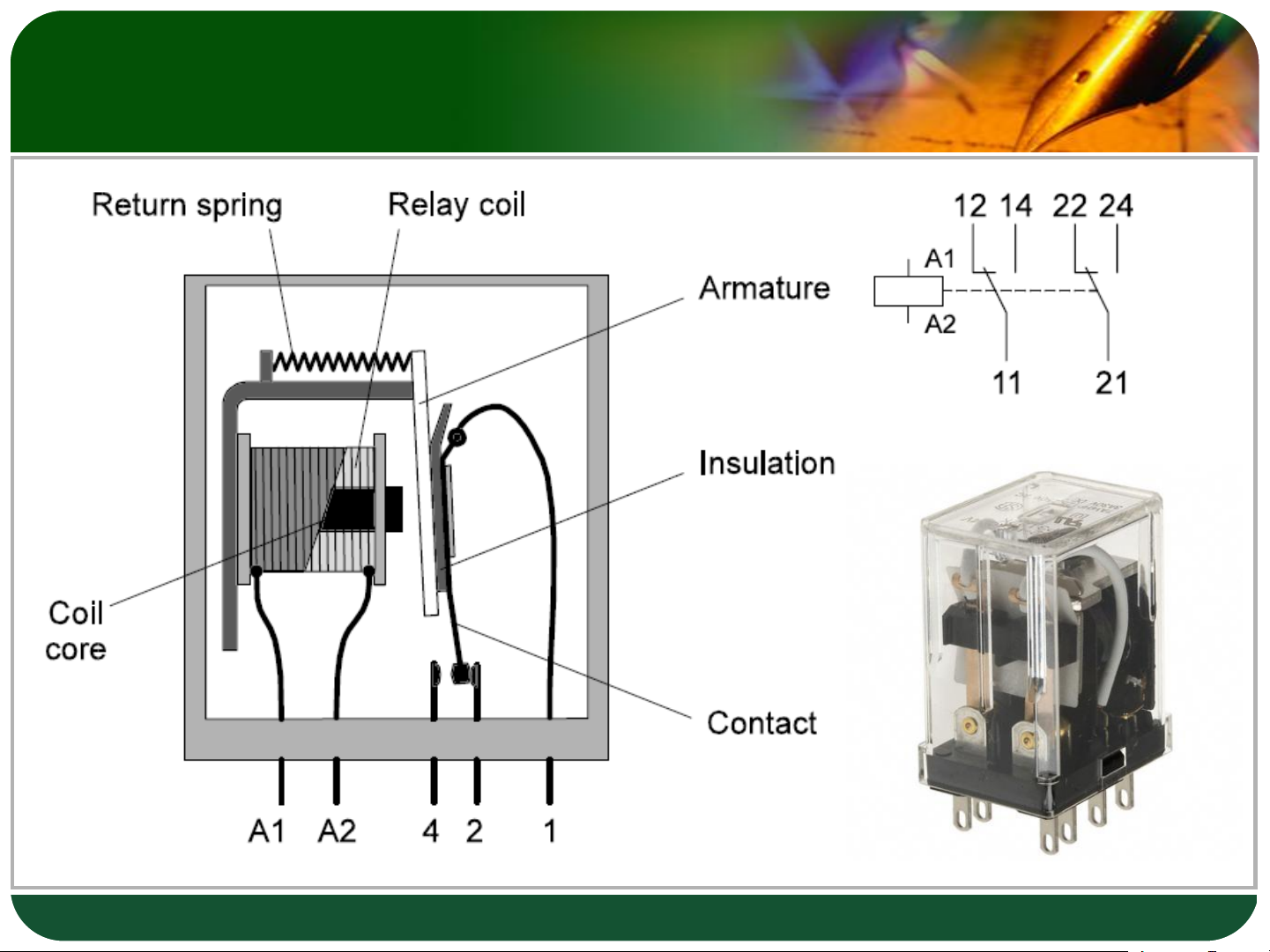
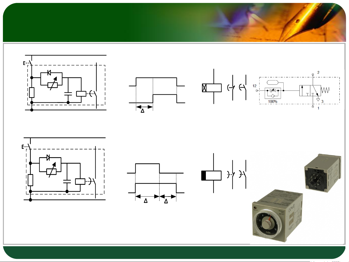
Sensor for measuring displacement 8 Relay 9 Time relay + 24 V
Relay with pull-in delay S1 D 1 3 A1 K K R1 C K K1 R2 A2 K1 2 4 0 V tA
Internal construction Signal behavior Symbol + 24 V S1
Relay with drop-out delay D 1 3 B1 K K R1 C K K1 R2 B2 K1 2 4 0 V tB tR 10
Electrically actuated directional control valves
❖ An electropneumatic control system works with two forms of energy:
- Electrical energy in the signal control section
- Compressed air in the power section. 11
Electrically actuated directional control valves
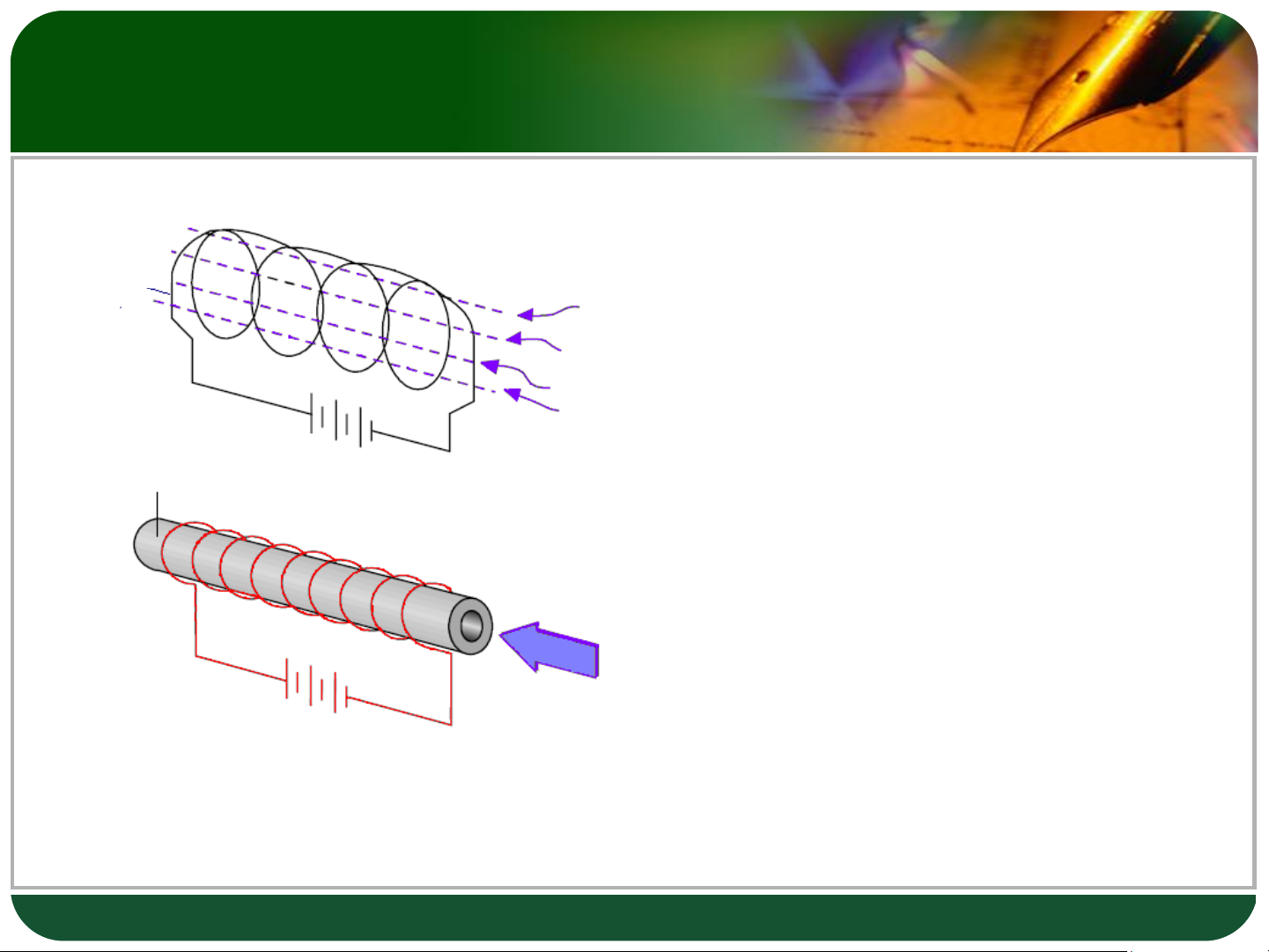
❖ Van ñieän töø (van solenoid): khi
➢ A magnetic field is
cuoän daây soleloid coù ñieän thì Coil induced when a current
seõ taùc ñoäng cho van ñaûo vò is passed through an trí laøm vieäc. electrical conductor.
Giaûi thích: Khi coù doøng ñieän
chaïy qua cuoän daây kim loaïi thì
seõ sinh ra töø tröôøng trong Iron core
➢ The strength of the
cuoän daây ñoù. Ñoä maïnh cuûa magnetic field is
töø tröôøng tyû leä vôùi cöôøng propotional to the
ñoä doøng ñieän. Töø tröôøng
current. Magnetic fields
huùt saét, niken vaø coban. Töø
attract iron, nickel and
tröôøng caøng maïnh thì löïc huùt cobalt. caøng maïnh.
➢ The attraction increases
❖ Keát luaän: cuoän daây kim loaïi
with the strength of the
chính laø moät nam chaâm ñieän, magnetic field.
khi cuoän daây kim loaïi coù
ñieän, noù seõ hoaït ñoäng gioáng 12
nhö moät nam chaâm, coù khaû
naêng huùt saét, niken vaø coban. Spring return 2/2 way
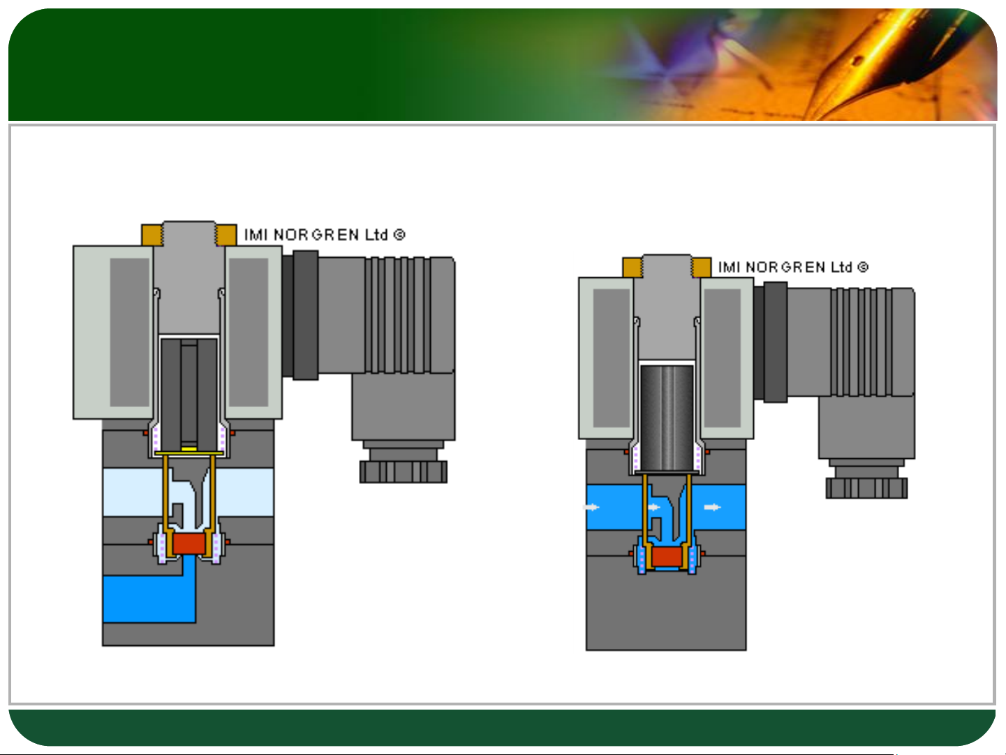
electrically actuated valve 13 Spring return 2/2 way
electrically actuated valve Normally Closed (NC) Normally Open (NO) 14 Spring return 3/2 way
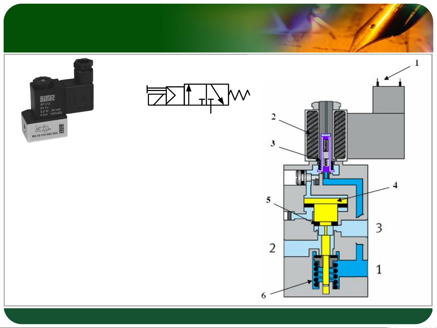
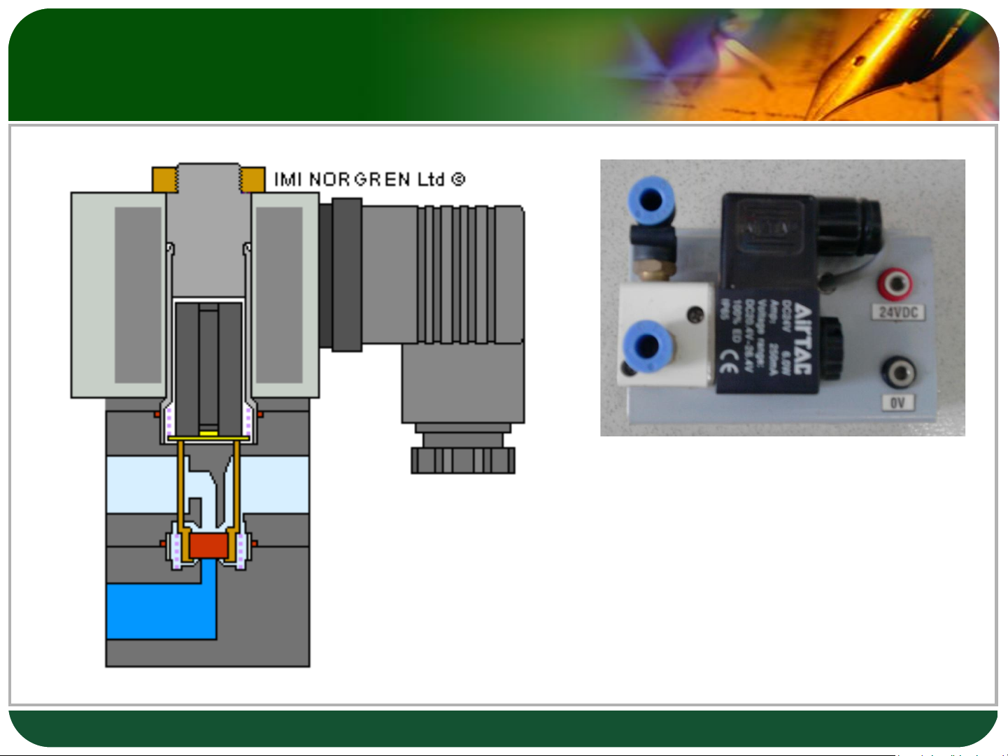
electrically actuated valve 2 1 3 2 Solenoid Coil 3 Armature 4 Valve piston 5 Upper sealing seat 6 Spring
In its initial position, the working port
Cöûa soá 1: Noái vôùi nguoàn khí
2 is linked to the exhaust port 3
Cöûa soá 2: Cöûa noái laøm vieäc
Cöûa soá 3: Cöûa xaû khí 15 Spring return 3/2 way
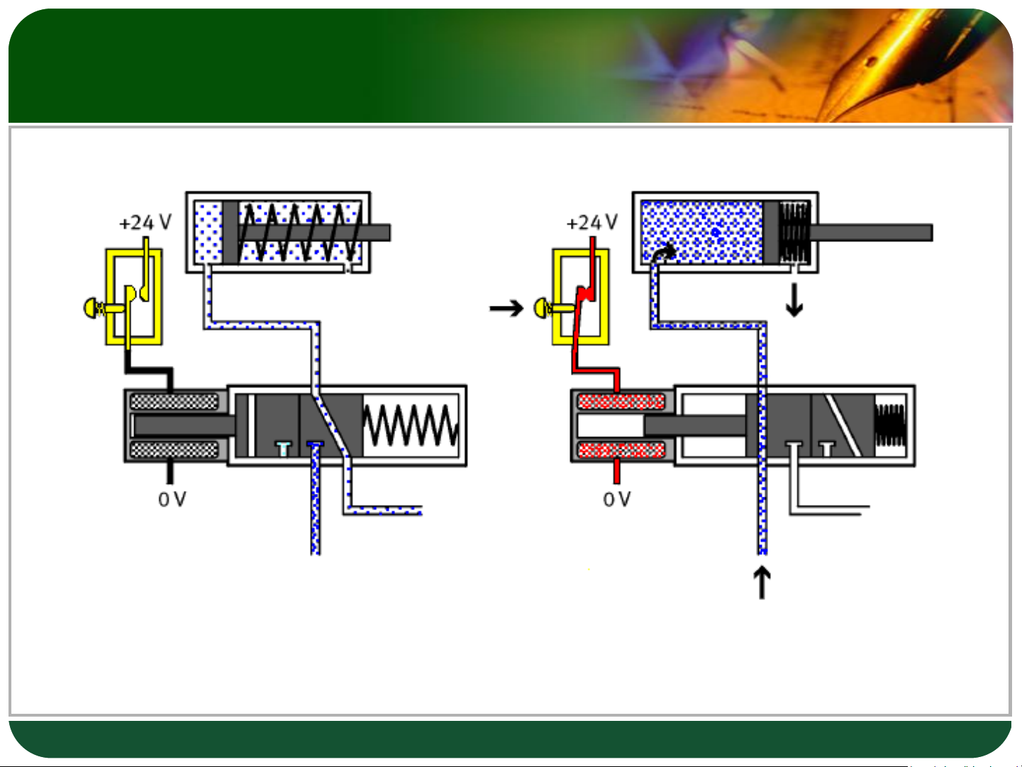
electrically actuated valve
If the solenoid coil is energized, the magnetic field forces the armature up against the pressure of a spring.
➢The lower sealing seat opens and the path is free for flow
from pressure port 1 to working port 2. ➢The upper sealing seat closes, shutting off the path between port 1 and port 3. 16 Spring return 3/2 way
electrically actuated valve
E:\Pics\Viet Nam\LGKP500\P130411_16.03.jpg 17 Example
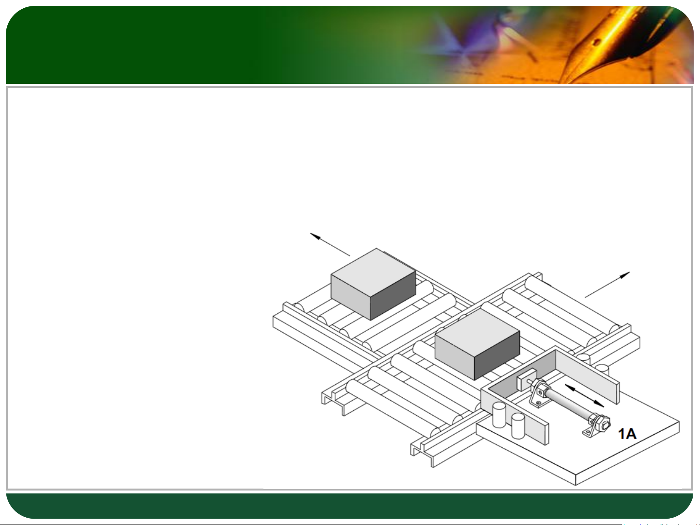
❖ Using a sorting device, parts are to be transferred from a conveyor belt.
❖ By pressing the pushbutton switch, the piston rod of a single-acting
cylinder pushes the part off the conveyor belt.
❖ When the pushbutton is released, the piston rod returns to the retracted end position. 18 Solution
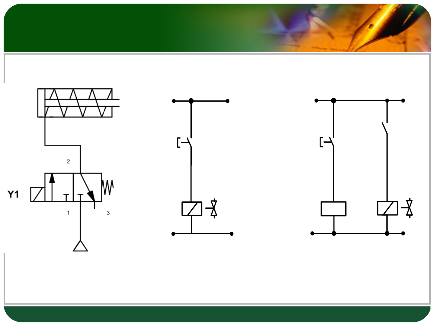
Pneumatic circuit diagram 19 Solution 1 1 2 + 24 V + 24 V K1 PB1 PB1 K1 Y1 Y1 0 V 0 V (a) (b)
Electric circuit diagram 20
Tài liệu liên quan:
-

Ung dung game hoa trong cac chien dich MKT
20 10 -
Bao cao Chi so TMDT Viet Nam 2025
18 9 -
Thông tư quy định về việc phân quyền, phân cấp và phân định thẩm quyền quản lý nhà nước về giáo dục cho chính quyền địa phương
25 13 -
Nghị quyết về phát huy các giá trị di sản văn hóa gắn với phát triên du lịch bền vững tỉnh Khánh Hòa đến năm 2025, định hướng đến năm 2030
15 8 -
Quyết định phê duyệt Chiến lược phát triển du lịch Việt Nam đến năm 2030
14 7