Chapter 7 Design electro-pneumatic circuit môn Pneumatic & Hydraulic Technologyac
Chapter 7 Design electro-pneumatic circuit môn Pneumatic & Hydraulic Technologyac . Tài liệu giúp bạn tham khảo, ôn tập và đạt kết quả cao. Mời đọc đón xem!
Môn: Tài liệu Tổng hợp 3.6 K tài liệu
Trường: Tài liệu khác 3.9 K tài liệu
Tác giả:


Preview text:
Pneumatic & Hydraulic Technology Chapter 7
Design electro-pneumatic circuit
Instructor: Phan Thi Thu Thuy
Instructor: Phan Thi Thu Thuy Email: thuyptt@hcmute.edu.vn Mobile Phone: H 0 ig 90 her 3.130Engi
.454 neering Education Alliance Program
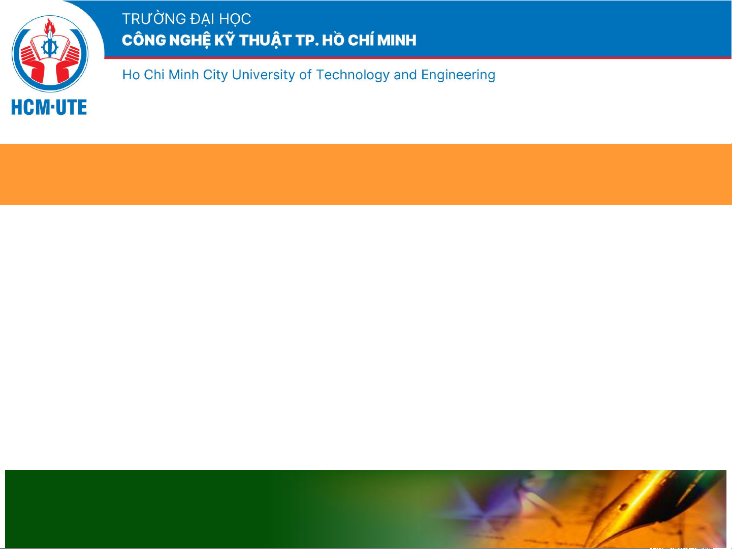
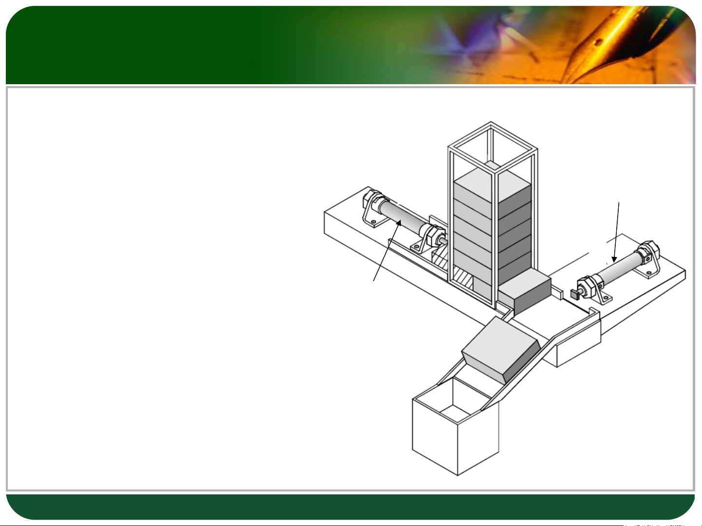
Example : Transfer Station The Problem:
❖ Two cylinders are used to transfer S1 Cylinder B parts from a S2 magazine onto a S3 chute. S4
❖ Confirmation of all Cylinder A extended and retracted positions are required. 2
Example : Transfer Station 3
EXAMPLE: TRANSFER STATION
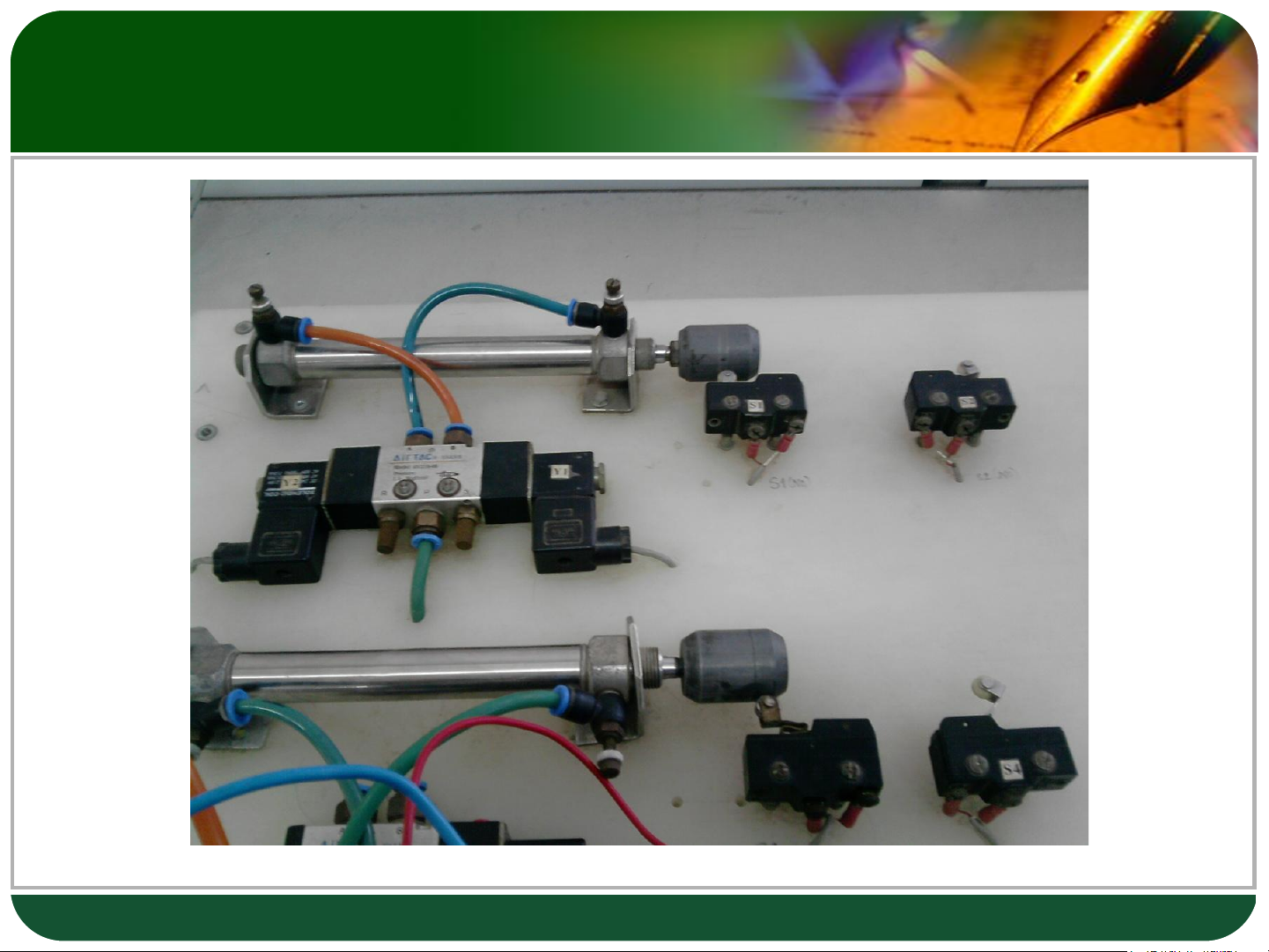
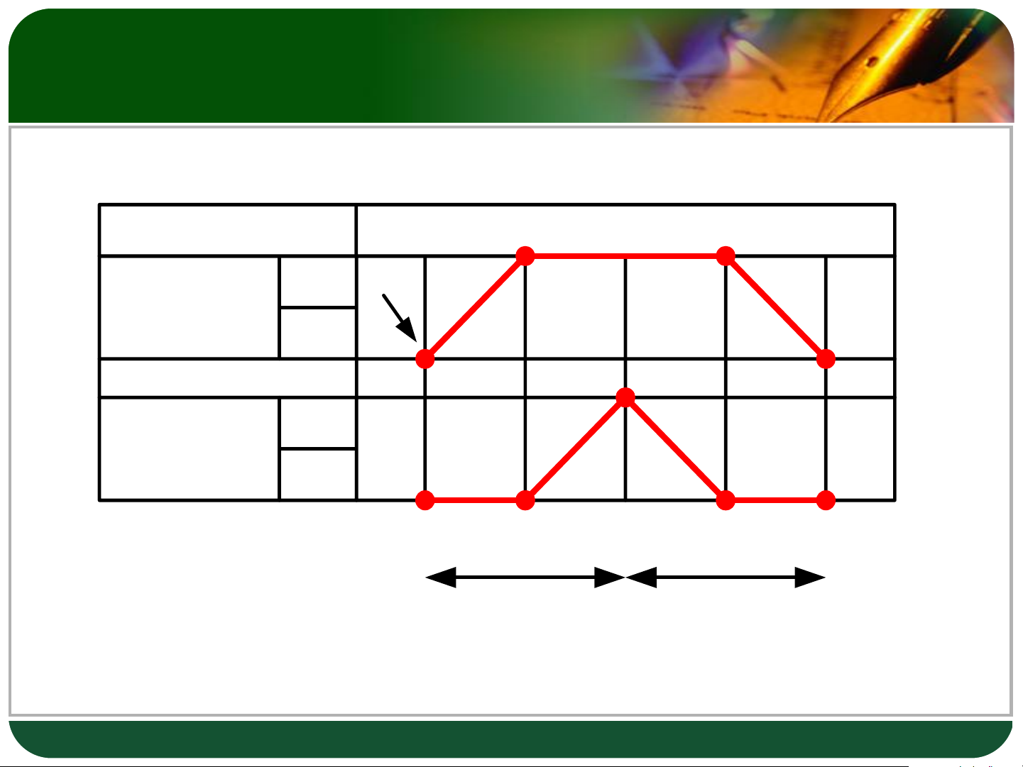
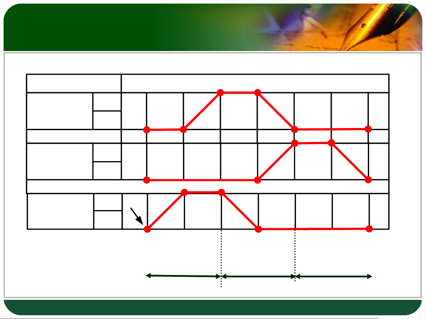
❖ Displacement-step diagram Step 1 2 3 4 5 = 1 S2 Start Cylinder A S1 S4 Cylinder B S3 I II Pressure supply lines
E1 = S1^Start: Starting signal of Pressure supply line I.
E2 = S4: Starting signal of Pressure supply line II. 4
Example : Transfer Station
The motion cycle can be determined from the
displacement-step diagram and is subdivided into the following steps:
❖ Step 1 Start and S1 actuated Cylinder A advances: A+ = Start ^ S1
❖ Step 2 S2 actuated Cylinder B advances: B+ = S2
❖ Step 3 S4 actuated Cylinder B retracts: B- = S4
❖ Step 4 S3 actuated Cylinder B retracts: A- = S3
❖ Step 5 S1 actuated Initial position 5 Control step signal
Control step signal = L (The number of line includes step)
+ Input signal of step
Note: If control step signal is similar to starting
signal of line, starting signal of line is the priority.
A+ = L1 (Do not combine Start ^ S1: Starting signal of line I) B+ = L1 ^ S2
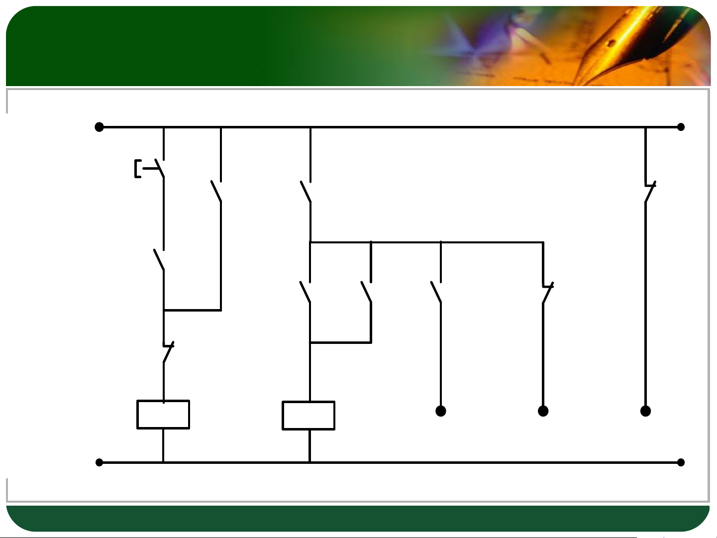
B- = L2 (Do not combine S4: Starting signal of line II) A- = L2 ^ S3 6 Cascade circuit 2 lines + 24 V Start K1 K1 K1 I E1 1 I e n e i ni L L E2 K1 0 V 7 Exercise 1: Testing
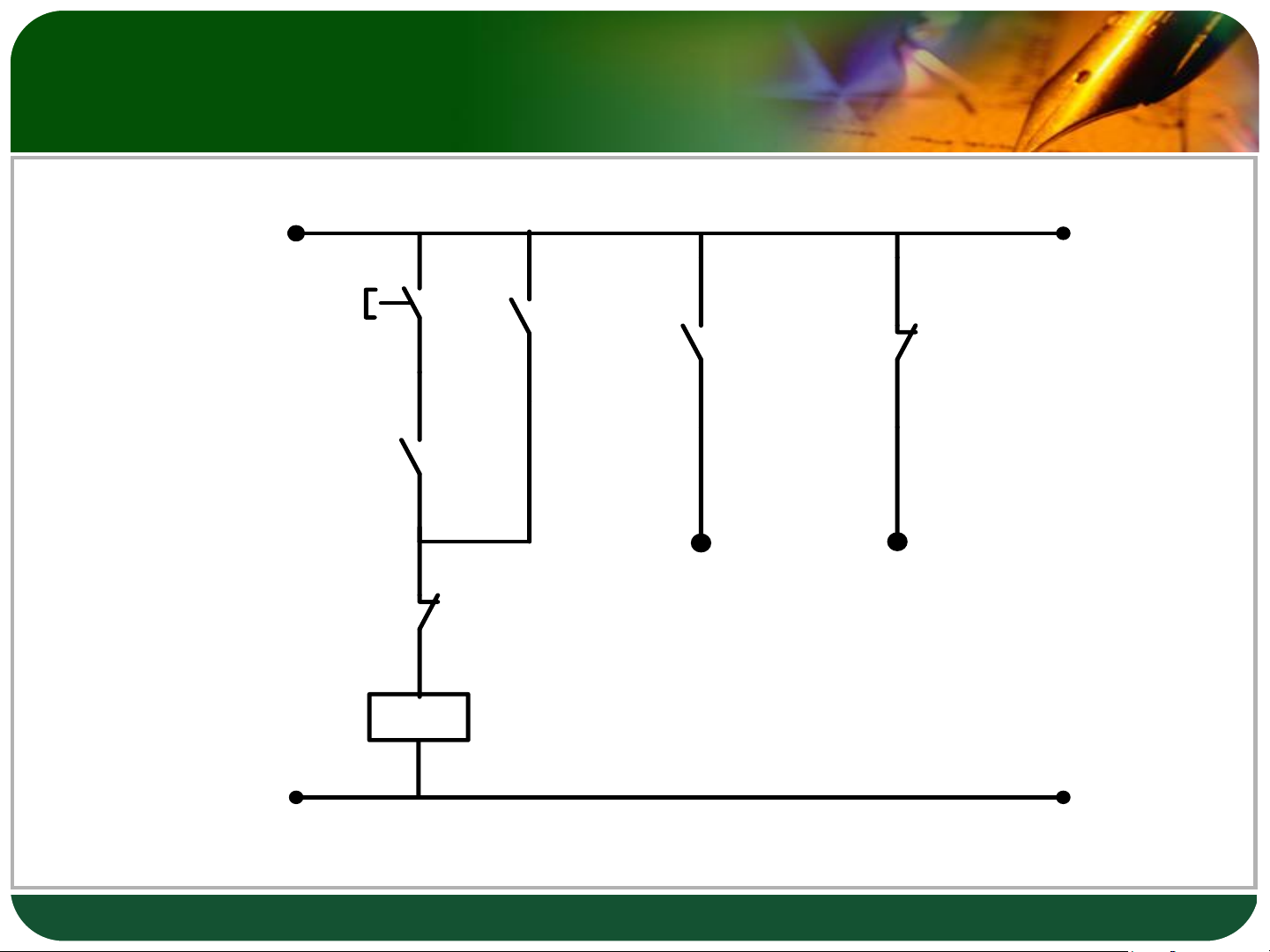
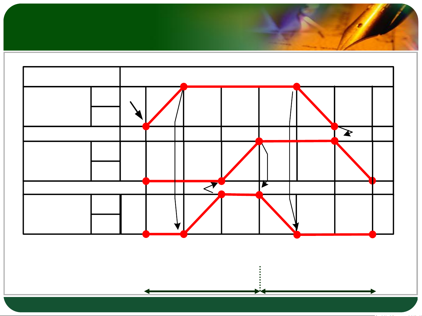
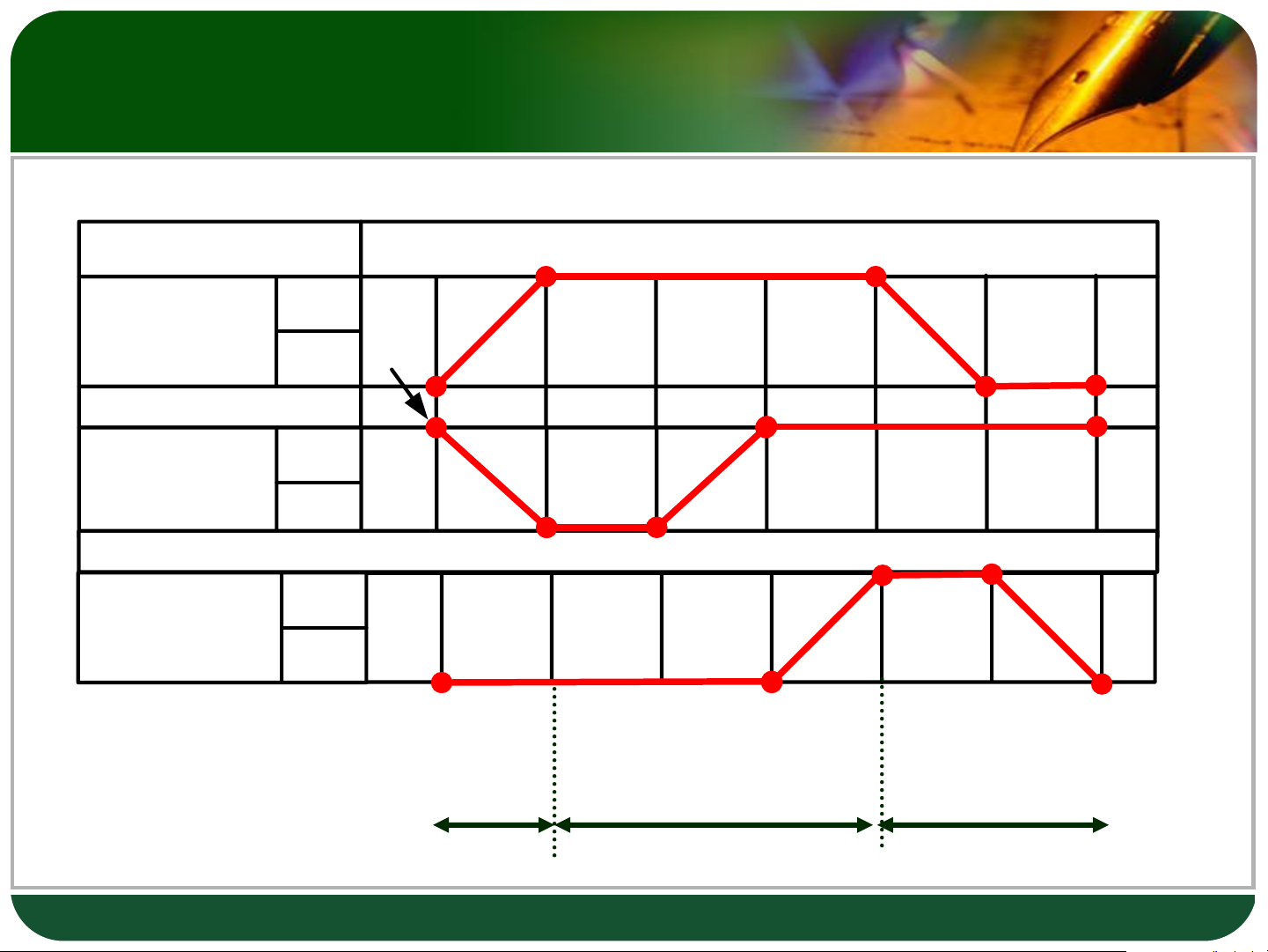
D:\HEEAP\Assignments HEEAP\2 Pneu-Hydraulics - Phan Thi Thu Thuy\0 Course pack - Pneumatic and Hydraulic Technology\3_Slides\Video_Animation\Index Animation 60 Examples\15 Testing - Image 1.bmp C A B 8 Exercise 1: Testing Step 1 2 3 4 5 6 7 = 1 S2 Start Gripper A S1 Rotary unit S4 B S3 Vertical S6 lifting unit C S5 A+ A+ C+ B+ C- A- B- I II 9 Exercise 2: Gluing Adhesive applicator device
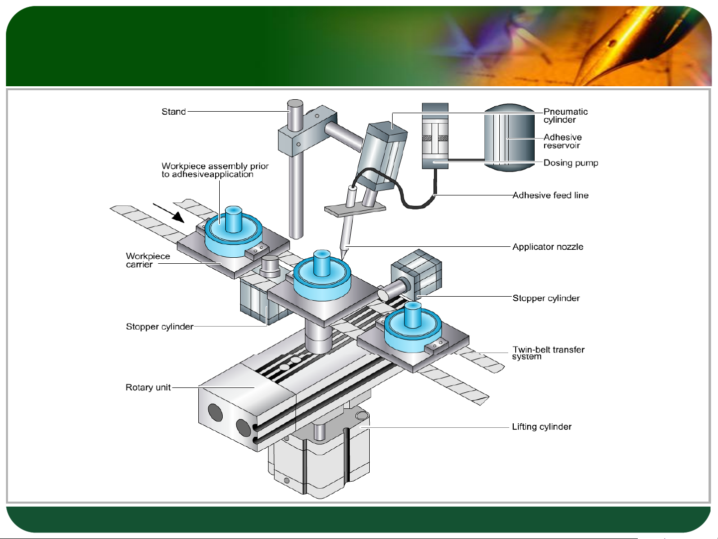
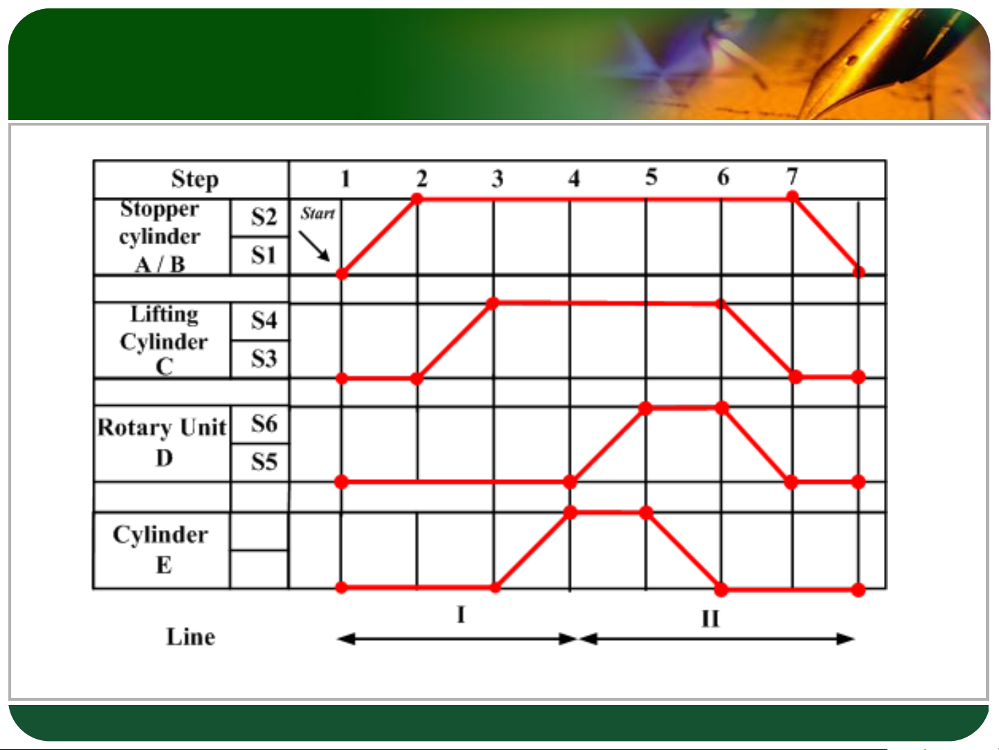
D:\HEEAP\Assignments HEEAP\2 Pneu-Hydraulics - Phan Thi Thu Thuy\0 Course pack - Pneumatic and Hydraulic Technology\3_Slides\Video_Animation\Index Animation 60 Examples\9 Glueing - Image 1.bmp E B A D C 10 Excercise 2: Glueing Adhesive applicator device 11 Exercise 3: Unloading
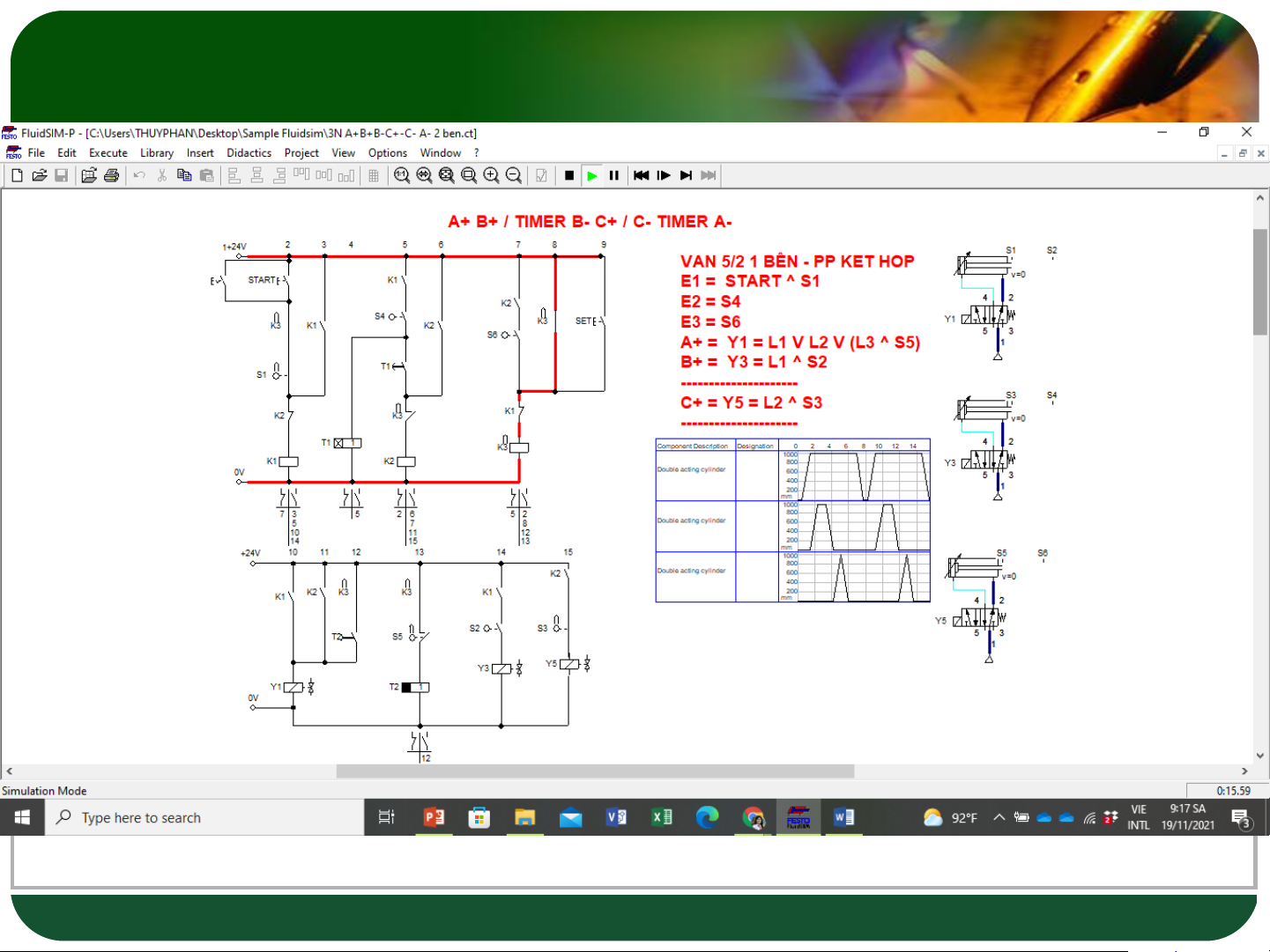
D:\HEEAP\Assignments HEEAP\2 Pneu-Hydraulics - Phan Thi Thu Thuy\0 Course pack - Pneumatic and Hydraulic Technology\3_Slides\Video_Animation\Index Animation 60 Examples\6 Unloading - Image.bmp A B 12 Excercise 3: Unloading Step 1 2 3 4 5 = 1 S2 Start Cylinder A S1 S4 Cylinder B S3 A+ A- B- B+ I II III 13 Cascade circuit 3 lines + 24 V Start K1 K1 K1 E1 E2 K2 K2 K2 E3 ine II ine I ine III L L L K1 0 V K2 14 Exercise 4 Step 1 2 3 4 5 6 7 = 1 S2 Start Cylinder A S1 S4 Cylinder B S3 S6 Cylinder C S5 A+ B+ B- C+ C- A- I II III 15 16 Exercise 5 Step 1 2 3 4 5 6 7 = 1 S2 Start Cylinder A S1 S4 Cylinder B S3 S6 Cylinder C S5 A+ B+ B- A- C+ C- I II III 17 Exercise 5 with Timer Step 1 2 3 4 5 6 7 8 S2 Start Cylinder A S1 S4 15s Cylinder B S3 S6 Cylinder C S5 18 Exercise 6 Step 1 2 3 4 5 6 7 = 1 Cylinder S2 A S1 Cylinder S4 15 B giây S3
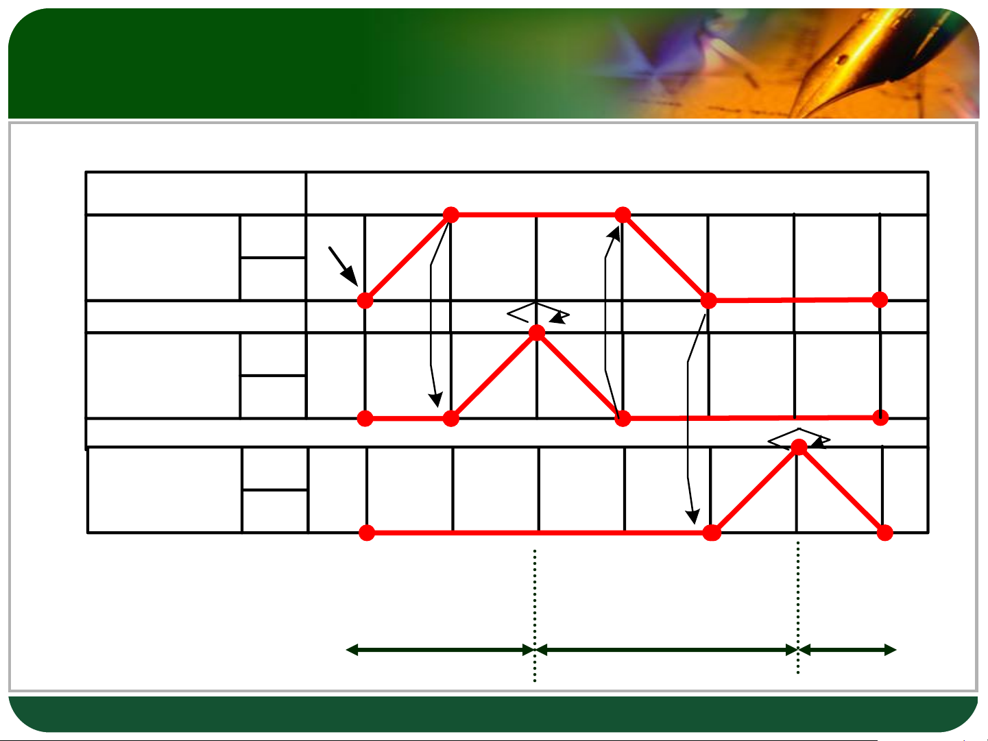
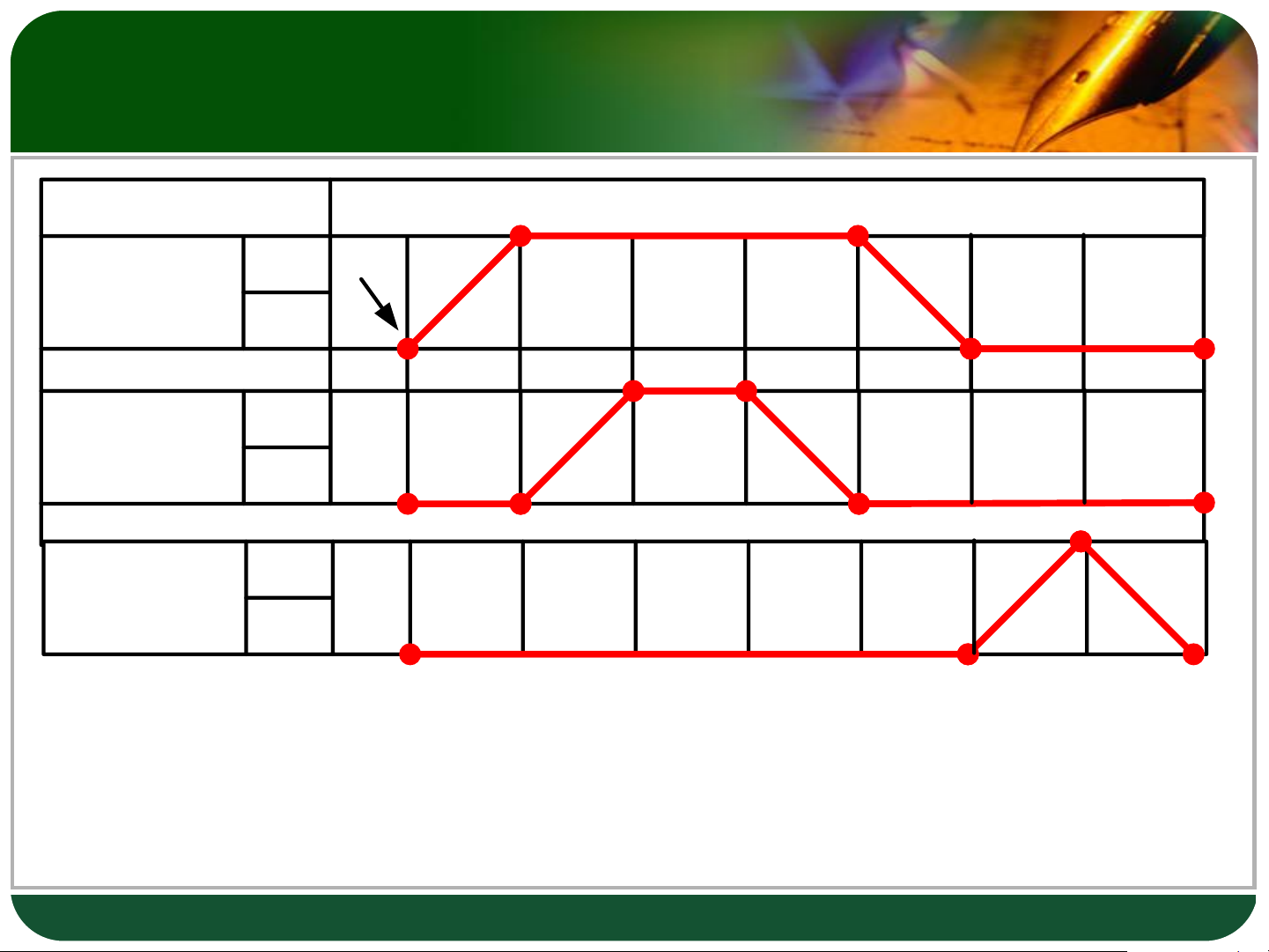
Cylinder S6 Start C S5 A+ B+ B- A- I II III C- 19 Exercise 7 Step 1 2 3 4 5 6 7 = 1 Cylinder S2 A S1 Start Cylinder S4 15 B giây S3 Cylinder S6 C S5 A+ I B+ B- A- II III 20
Tài liệu liên quan:
-

Ung dung game hoa trong cac chien dich MKT
20 10 -

Bao cao Chi so TMDT Viet Nam 2025
18 9 -
Thông tư quy định về việc phân quyền, phân cấp và phân định thẩm quyền quản lý nhà nước về giáo dục cho chính quyền địa phương
25 13 -
Nghị quyết về phát huy các giá trị di sản văn hóa gắn với phát triên du lịch bền vững tỉnh Khánh Hòa đến năm 2025, định hướng đến năm 2030
15 8 -

Quyết định phê duyệt Chiến lược phát triển du lịch Việt Nam đến năm 2030
14 7