Feasibility Study on Shunt Active Filter for Induction Heating System | Môn Computer Architecture and Organization Lab - Đại học Sư phạm Kỹ thuật Thành phố Hồ Chí Minh
Technological demands in industries change rapidly, due to changes in energy requirement, the need for loss minimization and changes in the market. Tài liệu được sưu tầm gồm 12 trang, giúp bạn ôn tập tốt hơn. Mời các bạn đón xem.
Môn: Computer Architecture and Organization Lab (COOL325364E) 10 tài liệu
Trường: Trường Đại học Sư phạm Kỹ thuật Thành phố Hồ Chí Minh 4.4 K tài liệu
Tác giả:


Preview text:
lOMoAR cPSD| 58605085
Available online at www.HighTechJournal.org HighTech and Innovation Journal
Vol. 2, No. 3, September, 2021
Feasible Evaluation of Shunt Active Filter for Harmonics Mitigation in Induction Heating System
Rahul Raman a, b, Subrata Kumar Dutta a, Priya Sarmah a*, Mrigakshi Das a,
Amarjit Saikia a, Pradip Kumar Sadhu b
a Department of Electrical Engineering, Jorhat Engineering College, Jorhat, 785007, India.
b Department of Electrical Engineering, Indian Institute of Technology (ISM), Dhanbad, 826004, India.
Received 05 January 2021; Revised 11 May 2021; Accepted 20 May 2021; Published 01 September 2021 Abstract
This paper propounds the incorporation of a three-level inverter based Shunt Active Filter (SAF) in the Induction Heating
(IH) system to eradicate the problems due to Electromagnetic Interference (EMI) & Radio Frequency Interference (RFI).
The IH system generates a considerable amount of high-frequency harmonics because of myriad causes, the predominant
one being the high-frequency switching in the resonant inverter. The former has an immanent propensity to flow towards
the supply side and results in the enfeeblement of power quality. Moreover, in the present work, attention has been paid
off to develop a proper control strategy of a three level inverter based SAF for EMI and RFI suppression. A new modeling
approach of three-level inverter based SAF is proposed and the efficacy and viability of the proposed controllers for SAF
in the IH system are validated via simulations in PSIM. A comparative analysis of THD in the input current waveform has
been done to advocate the desideratum of SAF as an imperative part of the IH system. Results obtained by simulations
show that the proposed approach is more effective than the reviewed approaches on compensating the harmonic currents
and thus, the filtering action of SAF is able to achieve the THD of input current within the limit specified by the IEEE-519 standard.
Keywords: EMI; RFI; Induction Heating; Shunt Active Filter; PSIM. 1. Introduction
Technological demands in industries change rapidly, due to changes in energy requirement, the need for loss
minimization and changes in the market. Hence existing technologies need upgradation very often to enhance the outcome
of the production and ensure smooth operation of the appliances. One such evolving technology is the Induction Heating
Equipment (IHE). It is a compact, highly efficient and easily controllable heating technique used for industrial as well as domestic heating purposes.
In IHE, electric energy is converted to heat energy by the application of Joule’s law of heating. The heating workpiece
is energized by high-frequency power generators like current source inverters which are in turn fed by ac to dc three phase
rectifiers. Utilization of various kinds of power converters and non-linear loads used for this purpose in industries
deteriorates the power quality, voltage and current waveforms. High-frequency switching operation of the inverter circuits
also produces a large number of current harmonics, which tend to move back towards the input of the circuit, deteriorate
the input current waveform [1-3] and reduce system stability. Current harmonics can also cause lOMoAR cPSD| 58605085
HighTech and Innovation Journal
Vol. 2, No. 3, September, 2021
* Corresponding author: priya30sarada@gmail.com
http://dx.doi.org/10.28991/HIJ-2021-02- 03-08
➢ This is an open access article under the CC-BY license (https://creativecommons.org/licenses/by/4.0/).
© Authors retain all copyrights.
interference problems in communication systems and leads to operation failure of electronic equipment. The grid voltage
however being robust remains almost unchanged.
Various passive and active filter circuit topologies have been explored in the past in order to suppress or compensate
the harmonic influx in the power supply to permissible limits. Passive filtering technique using LC filters and capacitor
banks is a very old technique of harmonic mitigation and reactive power compensation. Though this technique is very
simple and easy to implement, they have certain disadvantages like poor dynamic response, large inductor or capacitor
size, etc. Moreover, passive filtering techniques are mainly suitable for radio frequency range of operations. The use of
vienna rectifiers can reduce the problems related to electromagnetic and radiofrequency interference up to a great extent.
However, generation of reactive power is strictly restricted in vienna rectifiers as it functions only in the rectifier mode.
The direct control method of controlling Vienna rectifiers is imperfect as it allows unbalanced control sequences to appear.
The voltage space vector control also has certain limitations as demonstrated by Radomski et al. [3]. Due to these
limitations, active power filter circuits are preferred which can be conveniently used for reactive power compensation,
reduction of total harmonic distortion rate and suppression of harmonic currents of nonlinear loads, flowing back to the power supply [5-7].
The work reported by Akagi et al. (1983) [5], dealing with the calculation of reference compensation current signal
employing instantaneous reactive power theory (p-q theory) has inspired many researchers to work on the development
of better active power filter control strategies. In p-q theory, the input voltages and load currents are altered from the ab-
c frame of reference to the α-β reference frame, followed by determination of the p-q theory instantaneous power
components. The reference compensation currents can then be calculated. Po-Ngam (2014) [6] identified the load currents
and modified it to dq0 variables. The d-axis harmonic currents, q-axis and 0 axis currents are controlled by pi controller
with feedforward supply voltage via space vector inverter such that the THD of the three phase source currents are
decreased to 4.36, 4.46 and 4.51%. Chang et al. [7] proposed a new compensation strategy wherein the reference
compensation currents are determined in the a-b-c frame of reference, thus decreasing the complexity in realization of the
Active filter strategy. This approach requires a balanced source current, in phase with the positive sequence input voltage.
The Induction heating system proposed by Bojoi et al. [8] comprised a SAF with a DSP controller. Current is controlled
by Proportional-Sinusoidal Signal Integrators (P-SSI) and the controllers operate on the principle of selective harmonic
compensation and can be tuned for different harmonics [9].
Sharma et al. (2020) proposed a control strategy that enabled the working of the SAPF with reduced number of sensors.
The unit vector voltages are estimated using PLL, without sensing actual source voltage. The THD for nonlinear load was
found to be between 1.41 and 4.41% [11]. Colak et al. also proposed a sensorless DC voltage control based on the
calculation of filter power losses in a single-phase SAPF. The THD for the power system after the installation of the SAPF
was recorded in MATLAB at 2.85 and 1.64% respectively for two different non-linear loads. Although sensorless
techniques and parameter robustness is helpful in fault-tolerant control operation in case of sensor failure, they require
extensive PI controller tuning and high computational burden [12].
This paper highlights the use of a three-phase voltage source multilevel inverter, which is shunt connected through
inductors to a high frequency resonant inverter, used as power supply for induction heating. This shunt connected filter
circuit is mainly controlled for harmonic and reactive power compensation. The compensation currents are determined
by employing direct current control technique. The multilevel inverter uses multiple lower or medium level DC voltage
sources as input. They are very useful for industrial applications requiring high power and high voltage applications.
Moreover, the introduction of LCL filter in the active power filter circuitry helps achieve better filtering effect, resulting
in reduced THD, as proposed by Pan et al. (2019) and Park et al. (2017) respectively [13, 14]. The aim is to make the
main currents practically sinusoidal and in phase with respective phase voltages. The shunt active filter achieves this by
producing harmonics, equal in magnitude but in phase opposition to the harmonic components introduced by the
switching devices and nonlinear loads [6-9]. Simulations are carried out in the PSIM software to verify the outcome of the proposed model.
1.1. Shunt Active Filter for the Elimination of RFI and EMI
The non-linear load comprises of odd harmonics, which are odd multiples of the fundamental frequency. These
harmonic currents are incapable of contributing to the active power and leads to problems related to EMI and RFI. Thus,
harmonic currents need to be eliminated in accordance with the harmonic standards [1-6]. The high frequency harmonics
in the induction heating system (IHS) can be detected and eliminated efficiently using active filters. Active filters are lOMoAR cPSD| 58605085
HighTech and Innovation Journal
Vol. 2, No. 3, September, 2021
usually of two types – Series Active filter and Shunt Active filter. Series filters compensate for distortion in the power line
voltages [15-17] while Shunt Active filters (SAF) can compensate for both current harmonics and power factor. The latter
does not compensate load for load compensation load current harmonics though it provides high impedance to the
harmonics coming from the supply side.
The performance of a SAF depends upon many factors; the predominant ones being the reference signal generation
technique, quality of the current controller, modulation technique employed, etc. Hysteresis band and PWM control
methods have got wide popularity in the modulation techniques commonly used in SAFs. The former forces the inverter
output to stick to the reference signal. And for this purpose, a pair of switches is turned on and off when the error in the
current exceeds a certain magnitude.
In the proposed model, a three phase- three wire voltage source PWM multilevel inverter is used. This inverter circuit
is shunt connected at PCC to a nonlinear load comprising the IHE, through three input inductors. A low-cost switching
filter is used in order to get rid of the lower order harmonic currents and high-switching ripple currents generated due to
the combined effect of the input inductance and the main line inductance. The SAF will operate as a current source,
injecting the compensation current which is equal to the harmonic current but phase shifted by 180˚. Thus, the THD of
the system is reduced to give an optimized solution of the total system. Figure 1 shows the research methodology of the proposed method. Start
Problem Identification : Problems due
to E MI - RFI in the IH system
Defining Objectives of solution : Use of SAF to eliminate harmonics
Design and Implementation of SAF in the IH system
T HD calculation & comparison in
the input current waveform before and after installation of SAF
FFT analysis of the input current of IH system before and after installation of SAF Harmonics NO eliminated as per EMI - RFI regulations Yes E nd
Figure 1. Research methodology of the proposed method
1.2. Use of Multilevel Inverter
Most of the existing topologies of SAFs employ two-level Voltage Source Inverter (VSI). However, a better approach
is to use three-level VSI. In the present paper, a three-level neutral point diode clamped PWM inverter topology has been
used in the shunt active filter. Moreover, attention has been paid off to design a proper control strategy for the proposed
NPC based multi-level inverter. It has several distinct advantages over the traditionally used two level inverters. They
require only one common voltage source and consist of high frequency clamping diodes which limit the voltage stress on lOMoAR cPSD| 58605085
HighTech and Innovation Journal
Vol. 2, No. 3, September, 2021
power devices. Multilevel inverters have high power capability with minimum switching losses and output distortion [21-
23]. However, these advantages come at the cost of a more complex control strategy.
2. Proposed Model of IHE with Shunt Active Filter
Figure 2 shows the basic circuit diagram of IHE using the Shunt Active Filter. A diode bridge rectifier converts the
sinusoidal ac voltage from the three-phase supply to a pulsating dc voltage, which is fed to a high frequency resonant
inverter. The output of the inverter is fed to the induction heating load which generates heat energy by Joule’s law of
heating. The control circuit comprises a current control unit and a voltage control unit. .
Figure 2. Basic circuit diagram of IHE using Shunt Active Filter
Current sensors are used in all three phases to measure the instantaneous value of currents flowing in the supply line.
It is then passed through a second order band-pass filter (notch filter) whose centre frequency and stopping band are set
at 50 Hz and 20 Hz respectively. The choice of 50 Hz centre frequency ensures infinite impedance to the fundamental
component of current by the band stop filter. This in turn ensures blocking of the fundamental component of current while
allowing the smooth passage of all other frequency components. The band-stop filter is well tuned to block the
fundamental frequency component while allowing other harmonic components of current. Thus, the output of the bandstop
filter compromises the harmonic currents only. Finally, it is subtracted from the current obtained by the current sensors from the main line.
In the present work, attention has also been paid off to maintain a constant dc voltage at the input capacitor of the multi-
level inverter. The latter is sensed and subtracted from a reference value and then fed to a low pass filter and PI controller.
Then, it is synchronized with the three-phase input and multiplied with the output obtained from the difference of sensed
current and output of band-stop filter (iIH)h. The aforementioned technique is employed in all three phases. From the
present value, the output of the multi-level inverter obtained by the current sensor is subtracted. Then, it is fed to a PI
controller and limiter. Finally, it is fed to a hysteresis comparator to generate switching signal for the multi-level inverter.
Thus, the SAF produces harmonic currents (iSAF) which are applied at the point of common coupling (PCC). This
compensating current mitigates the harmonic currents generated by the nonlinear loads and switching devices. Accurate
generation of the reference current signal and proper control of the gate firing pulses of the filter is thus necessary for effective compensation.
Instantaneous current in the input is given by; (1)
iIN (t) iIH (t) iSAF (t)
The instantaneous voltage at the source is given by lOMoAR cPSD| 58605085
HighTech and Innovation Journal
Vol. 2, No. 3, September, 2021
EIN (t) Emax sin t (2)
When high frequency IH system is fed by the supply, then the current at the input of the IH system comprises of
fundamental & harmonic components and may be showed as follows: EIN (t)
iIN (t) (IIH )1 sinwtcos 1 (9) (I IN )m (IIH )1 cos (10) Then, lOMoAR cPSD| 58605085
HighTech and Innovation Journal
Vol. 2, No. 3, September, 2021 (3) iIH (t)
(IIH )m sin(m t m ) m 1 (4)
iIH (t) (IIH )1 sin( t 1)
(IIH )m sin(m t m ) m 2 (5)
The instantaneous power fed to the IH system is given by: P (6) IH (t)
Emax sin t(IIH )1sin tcos 1 Emax (IIH )1sin t.cos t.sin 1 Emax sin t (IIH )m sin(m t m) m 2 (7)
PIH (t) PIH, f (t) PIH,r (t) PIH ,h(t)
PIH (t) Emax sin2 tcos 1 Emax (IIH )1sin t.cos t.sin 1 Emax sin t (IIH )m sin(m t m) (8) m 2
After compensation of current harmonics by the current supplied by SAF, the source current is given by:
PIH , f (t) iIN (t)
iIN ( )t (IIH m) sinwt (11)
The source needs to supply some extra power along with the real power required in the IH system to maintain a constant
capacitor voltage at the input of SAF and also to meet the converter losses. Thus, total peak input current is given by; (I IN )peak (IIN )m ICL (12)
The shunt active filter (SAF) produces current harmonics that compensates the harmonics in the current iIH because the
former & latter are 180° out of phase.
Thus, the compensating current supplied by the SAF is given by;
iSAF(t) iIH (t) iIN (t) (13)
So, it is important to accurately compensate the instantaneous reactive & harmonic power. And for this purpose, it is
necessary to calculate the fundamental component of current fed to the IH system as the reference current.
2.1. Estimation of Reference Current:
The dc capacitor at the input of SAF can be controlled for estimating the peak value of reference current (I)peakin the source
side. The compensation of harmonic currents will be ideal when the input current is completely sinusoidal.
Moreover, the latter should be in phase with the supply voltage irrespective of the harmonics present on the load side.
After compensation, it is desirable to achieve the following current on the input side.
iIN* ,a (IIN )peak sin t (14) i IN* ,b
(IIN ) peak sin( t 120) (15) lOMoAR cPSD| 58605085
HighTech and Innovation Journal
Vol. 2, No. 3, September, 2021
iIN* ,c (IIN ) peak sin( t 120 ) (16) Where;
(IIN ) peak (IIH )1 cos ICL (17)
Equation 17 represents the amplitude of current desirable at the input side while the input voltage may be used for
determining the phase angles. This in turn indicates that the waveform & shape of the input current is known & only the
magnitude needs to be calculated.
As per the notations taken in Figure 2: i * * *
M (t) [kp (EDC
EDC ) ki (EDC EDC )dt]sin(wt) (18) Again, we know iC* iM iM* (19) Where; * iMp iloss (20) iM
Where, iMP is the real part of current and iloss represents the losses in the filter circuit. iM iMp iMq iMh (21)
IMq and iMh are the reactive components and harmonic components of the current. Therefore;
iC* iloss iMq iMh (22)
The voltage of the dc capacitor at the input of SAF needs to be regulated for estimating the peak value of reference
current. The former is compared with a dc reference value (400V in the present case) and error obtained is fed to a PI controller.
2.2. Use of the DC Capacitor
The capacitor installed at the dc side is used to assert a dc voltage with the allowance of minimum ripples in steady
state. Ideally, during this period, the source supplies real power, which is equal to the load power demand. The former
also supplies a small amount of power to compensate for the active filter losses. But, during the transient period, due to
changes in the load demand, there is a difference in real power between the load and the source. The dc capacitor
compensates for this real power difference. As a result, the dc capacitor voltage which was initially maintained at a
reference value also changes. If the peak value of the reference current is regulated such that it changes in proportion to
the real power drawn from the source, the active filter can be satisfactorily operated. In order to balance the real power
demand between the source and the load, the dc capacitor voltage needs to be recovered and maintained at the reference voltage.
2.3. Use of the PI Controller
In the present paper, PI controllers have been employed to provide appropriate system control. In the voltage control
unit, the PI controller is used to correct the error between the input DC capacitor voltage of the multilevel inverter and a
reference value. The difference between the two is calculated and then some corrective measures are introduced to get a desired outcome. lOMoAR cPSD| 58605085
HighTech and Innovation Journal
Vol. 2, No. 3, September, 2021
The proportional response to the error value is regulated by multiplying the error with proportional gain kp, while the
integral mode helps to restore the desired DC voltage with minimum delay by calculating the accumulated proportional
offset over time. The constants kp and ki of the PI controller can be obtained from the characteristics of the voltage control loop as: 1 (k ] 0 P
ksi )3[Vin CLCDCICoVDCos S2ICoRC (23)
Here, kp determines the voltage response and ki defines the damping factor of the voltage loop.
The amplitude of the current desired in the input side may be considered as the output of the aforesaid PI controller.
For estimation of the reference currents, the unit sine vectors which are in phase with the input voltage are multiplied with
the aforesaid peak value. The reference currents and actual currents from the multilevel inverter are fed to a hysteresis
PWM controller which in turn generates the switching signals. These signals are properly segregated and amplified, before
applying to the switching devices. In view of the switching activities, current flows through the SAF inductor Lc and thus
cancels out the harmonic currents in the system.
3. Simulation Diagram and Results
In the present paper, all the simulations have been executed in the PSIM platform. PSIM is simulation software
particularly designed for power electronics and motor control. Simulation is performed on a high frequency induction
heating system with and without the shunt active filter such that the effect of the Shunt APF on the IHE can be observed
and compared. The simulation results hence acquired for the above cases are studied, the input currents are assimilated
and their FFT analysis is carried out. Figure 3 shows the simulation circuit diagram of IHE before the installation of SAF
and the corresponding input current waveform and its FFT analysis are shown in Figures 3(a) and 3(b) respectively. Figure
4 shows the simulation circuit diagram of IHE after the installation of SAF. The input current waveform followed by its
FFT analysis are shown in Figures 4(a) and 4(b) respectively.
Figure 3. Simulation diagram of IHE before installation of SAF
Figure 3(a). Input current waveform analysis of the IHE before installation of SAF lOMoAR cPSD| 58605085
HighTech and Innovation Journal
Vol. 2, No. 3, September, 2021
Figure 3(b). Input current FFT analysis of IHE before installation of SAF
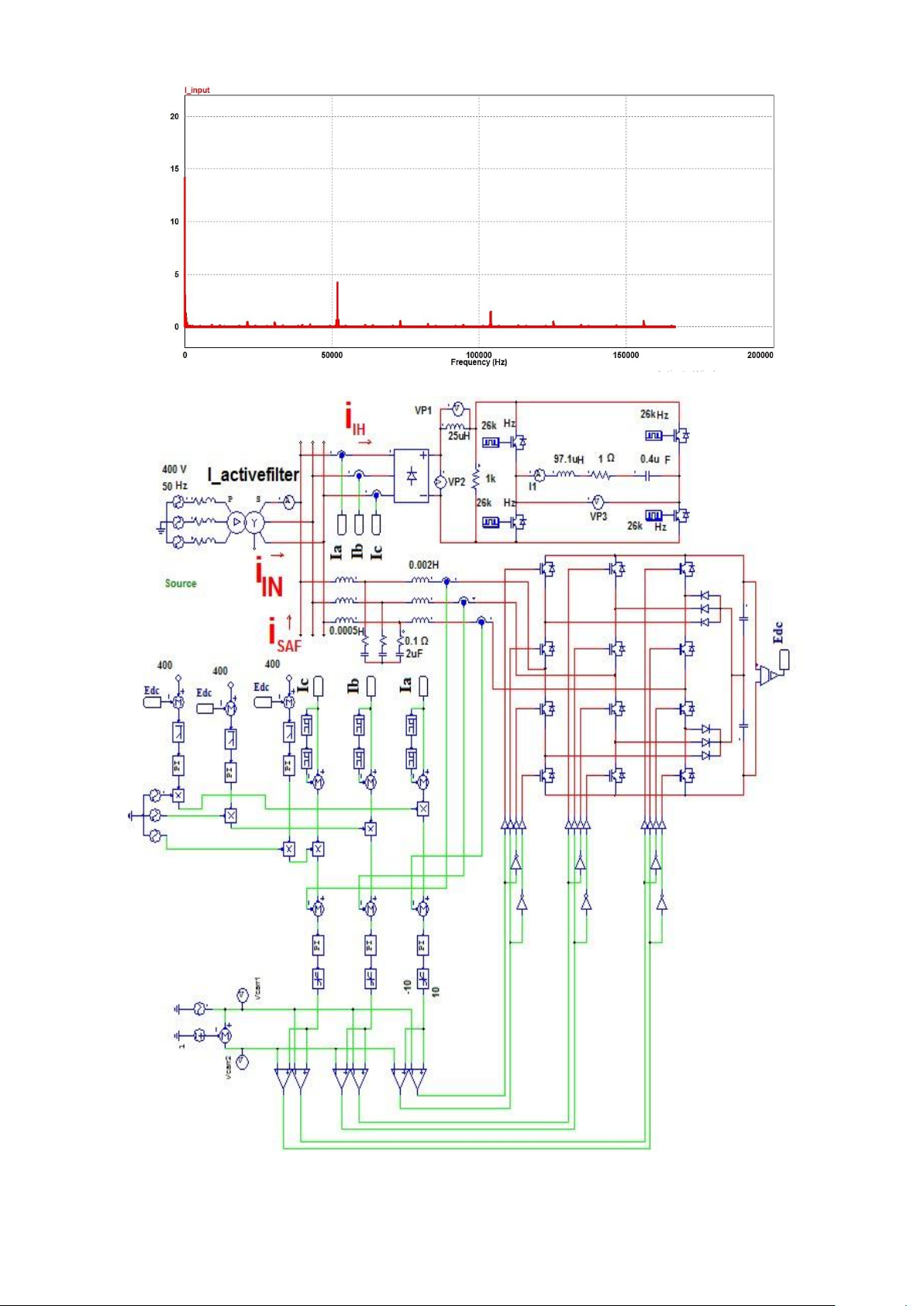
Figure 4. Simulation Diagram of IHE after installation of SAF lOMoAR cPSD| 58605085
HighTech and Innovation Journal
Vol. 2, No. 3, September, 2021
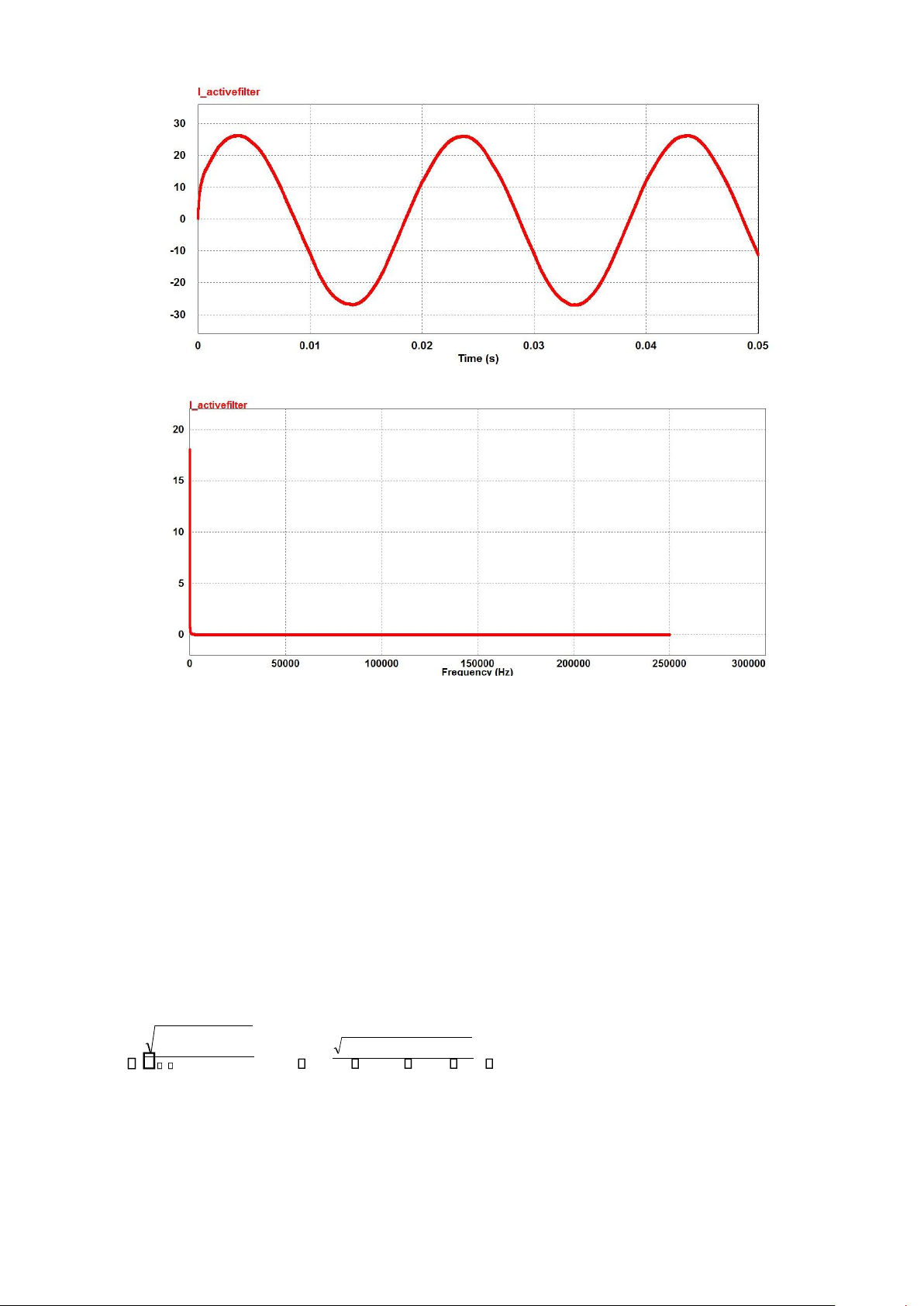
Figure 4(a). Input current waveform analysis of IHE after installation of SAF
Figure 4(b). Input current FFT analysis of the IHE after installation of SAF
The FFT analysis of the input current waveform without the incorporation of shunt active filter shows the presence of
some predominant harmonic components and as a result of that the total harmonic distortion was found to be 33.3%. With
the incorporation of the shunt active filter, the harmonic spectrum is improved and the total harmonic distortion is reduced
to 0%. All the components that have been used in PSIM are ideal in nature. Henceforth, the shunt active filter is able to
successfully eliminate all the high frequency harmonic components that were causing a considerable amount of
deterioration in the power quality. So, it justifies the necessity and importance of shunt active filter in an induction heating system. 4. Calculation of THD
From the simulation results and FFT analysis, the THD is calculated as follows:
4.1. Before SAF installation
The FFT analysis of the source current waveform in the absence of the SAF is observed to be non-sinusoidal in nature
and contains three predominant and a few negligible harmonic components alongside the fundamental current component. THD
n 2 (Iline)2n,rms THD 4.6692 0.8522 0.252 100 33.3%
I(line)1,rms 14.231
4.2. After the installation of SAF
After the installation of the SAF in the IHE, the FFT analysis is performed again. The analysis shows that the harmonics
are eliminated completely. Practical implementation of this model may give rise to very negligible value of THD due to lOMoAR cPSD| 58605085
HighTech and Innovation Journal
Vol. 2, No. 3, September, 2021
small imperfections in the equipment’s used. Here we have used ideal components, thus it is showing nearly zero THD value. 5. Conclusion
The present work deals with the elimination of the high frequency harmonics available on the supply line. Induction
heating at high frequency has lot many advantages over the traditional models. But operation at high frequency has got
several disadvantages like electromagnetic and radio frequency interference and the production of harmonics, resulting in
the deterioration of power quality.
Many techniques are available for elimination of harmonics but the total harmonic distortion was considerably higher
in all the existing topologies. So, in the present work attention has been paid off in designing the controller for the shunt
active filter that can attenuate the harmonic components present in the supply line in a very efficient way.
The THD of the current waveform at the input side of the Induction Heating Equipment before the installation of SAF
was found to be 33.3%. However, after the installation of SAF the harmonics which were present are eliminated
completely. Thus, it justifies that the SAF successfully performs harmonic damping in the Induction Heating Equipment
resulting in increased power factor and lower THD. 6. Declarations 6.1. Author Contributions
Conceptualization, R.R.; methodology, R.R. and P.S.; software, S.K.D., M.D. and A.S.; validation, R.R., M.D. and
A.S.; formal analysis, R.R., P.S. and P.K.S.; investigation, M.D. and P.S.; resources, A.S. and S.K.D.; data curation,
M.D., A.S. and P.K.S.; writing—original draft preparation, R.R., S.K.D., P.S., M.D., A.S. and P.K.S.; writing— review
and editing, R.R., S.K.D., P.S., M.D. and A.S.; visualization, P.S., M.D., S.K.D. and A.S.; supervision, P.K.S.; project
administration, R.R. and P.K.S. All authors have read and agreed to the published version of the manuscript.
6.2. Data Availability Statement
The data presented in this study are available on request from the corresponding author. 6.3. Funding
The authors received no financial support for the research, authorship, and/or publication of this article. 6.4. Acknowledgements
The authors would like to express their deep appreciation and indebtedness to Indian Institute of Technology (ISM),
Dhanbad and Jorhat Engineering College, Assam for providing the necessary research assistance for the completion of the work.
6.5. Declaration of Competing Interest
The authors declare that they have no known competing financial interests or personal relationships that could have
appeared to influence the work reported in this paper. 7. References
[1] Pal, P., Sadhu, P. K., Pal, N., & Sanyal, S. (2015). An exclusive design of EMI-RFI suppressor for modified half bridge inverter
fitted induction heating equipment. International Journal of Mechatronics, Electrical and Computer Technology (IJMEC), 5(15), 2084-2100.
[2] Raman, R., Sadhu, P. K., Kumar, A., & Sit, K. (2018). Design and analysis of RFI and EMI suppressor for high frequency
induction heater using filters — A comparative study. 2018 4th International Conference on Recent Advances in Information
Technology (RAIT). doi:10.1109/rait.2018.8389002.
[3] Radomski, G. (2005). Analysis of vienna rectifier. Electrical Power Quality and Utilisation. Journal, XI (1), 49-56.
[4] Raman, R., Das, M., Sarmah, P., Dutta, S. K., Saikia, A., & Sadhu, P. K. (2020). Design and Analysis of Series Resonant Inverter-
Based Induction Heating Equipment Employing Power Factor Correction for Harmonic Attenuation. Lecture Notes in Electrical
Engineering, 499–510. doi:10.1007/978-981-15-8586-9_44.
[5] H. Akagi, Y. Kanazawa and A. Nabae (1983). Generalized Theory of the Instantaneous Reactive Power in Three Phase Circuits.
Proc. IEEJ Int. Power Electronics Conference, 1375-1386, Tokyo, Japan.
[6] Po-Ngam, S. (2014). The simplified control of three-phase four-leg shunt active power filter for harmonics mitigation, load
balancing and reactive power compensation. 2014 11th International Conference on Electrical Engineering/Electronics,
Computer, Telecommunications and Information Technology (ECTI-CON). doi:10.1109/ecticon.2014.6839832. lOMoAR cPSD| 58605085
HighTech and Innovation Journal
Vol. 2, No. 3, September, 2021
[7] Chang, G. W., & Shee, T.-C. (2004). A Novel Reference Compensation Current Strategy for Shunt Active Power Filter Control.
IEEE Transactions on Power Delivery, 19(4), 1751–1758. doi:10.1109/tpwrd.2004.835430.
[8] Bojoi, R., Griva, G., Profumo, F., Cesano, M., & Natale, L. (n.d.). Shunt active power filter implementation for induction heating
applications. Twentieth Annual IEEE Applied Power Electronics Conference and Exposition, 2005. APEC 2005.
doi:10.1109/apec.2005.1453264.
[9] Bojoi, R. I., Griva, G., Bostan, V., Guerriero, M., Farina, F., & Profumo, F. (2005). Current Control Strategy for Power
Conditioners Using Sinusoidal Signal Integrators in Synchronous Reference Frame. IEEE Transactions on Power Electronics,
20(6), 1402–1412. doi:10.1109/tpel.2005.857558.
[10] Yu-hang, L., Yang-jing, Li-hao, & Wang-chao. (2016). The research of three phase four wire active power filter on small independent micro-grid. 2016 China International Conference on Electricity Distribution (CICED).
doi:10.1109/ciced.2016.7576008.
[11] Sharma, S., Verma, V., & Behera, R. K. (2020). Real-Time Implementation of Shunt Active Power Filter with Reduced Sensors.
IEEE Transactions on Industry Applications, 56(2), 1850–1861. doi:10.1109/tia.2019.2957734.
[12] Colak, I., & Kaplan, O. (2019). Design and Implementation of Sensorless DC Voltage Regulation for Shunt Active Power Filter
Based Single Phase P-Q Theory. 2019 8th International Conference on Renewable Energy Research and Applications (ICRERA).
doi:10.1109/icrera47325.2019.8996561.
[13] Pan, N., & Liu, Z. (2019). A design method of LCL-filter for three-phase shunt active power filter. doi:10.1063/1.5090707.
[14] Park, K.-B., Kieferndorf, F. D., Drofenik, U., Pettersson, S., & Canales, F. (2017). Weight Minimization of LCL Filters for High-
Power Converters: Impact of PWM Method on Power Loss and Power Density. IEEE Transactions on Industry Applications,
53(3), 2282–2296. doi:10.1109/tia.2017.2657479.
[15] Luo, Z., Su, M., Sun, Y., Zhang, W., & Lin, Z. (2016). Analysis and control of a reduced switch hybrid active power filter. IET
Power Electronics, 9(7), 1416–1425. doi:10.1049/iet-pel.2015.0027.
[16] Swain, S. D., Ray, P. K., & Mohanty, K. B. (2017). Improvement of Power Quality Using a Robust Hybrid Series Active Power
Filter. IEEE Transactions on Power Electronics, 32(5), 3490–3498. doi:10.1109/tpel.2016.2586525.
[17] Javadi, A., Hamadi, A., Woodward, L., & Al-Haddad, K. (2016). Experimental Investigation on a Hybrid Series Active Power
Compensator to Improve Power Quality of Typical Households. IEEE Transactions on Industrial Electronics, 1–1. doi:10.1109/tie.2016.2546848.
[18] Tareen, W. U., Mekhilef, S., Seyedmahmoudian, M., & Horan, B. (2017). Active power filter (APF) for mitigation of power
quality issues in grid integration of wind and photovoltaic energy conversion system. Renewable and Sustainable Energy
Reviews, 70, 635–655. doi:10.1016/j.rser.2016.11.091.
[19] Asiminoaei, L., Lascu, C., Blaabjerg, F., & Boldea, I. (2007). Performance Improvement of Shunt Active Power Filter With Dual
Parallel Topology. IEEE Transactions on Power Electronics, 22(1), 247–259. doi:10.1109/tpel.2006.888912.
[20] Lee, T.-L., & Hu, S.-H. (2016). An Active Filter With Resonant Current Control to Suppress Harmonic Resonance in a
Distribution Power System. IEEE Journal of Emerging and Selected Topics in Power Electronics, 4(1), 198–209.
doi:10.1109/jestpe.2015.2478149.
[21] Jeong, I. W., & Sung, T. H. (2021). One-Cycle Control of Three-Phase Five-Level Diode-Clamped STATCOM. Energies, 14(7), 1830. doi:10.3390/en14071830.
[22] Al-Shetwi, A. Q., Hannan, M. A., Jern, K. P., Mansur, M., & Mahlia, T. M. I. (2020). Grid-connected renewable energy sources:
Review of the recent integration requirements and control methods. Journal of Cleaner Production, 253, 119831.
doi:10.1016/j.jclepro.2019.119831.
[23] Jain, S. (2018). Control Strategies of Shunt Active Power Filter. Modeling and Control of Power Electronics Converter System
for Power Quality Improvements, 31–84. doi:10.1016/b978-0-12-814568-5.00002-8.
Tài liệu liên quan:
-

Revise C++: Create Your First OOP Project Guide | Môn Computer Architecture and Organization Lab - Đại học Sư phạm Kỹ thuật Thành phố Hồ Chí Minh
98 49 -

Bài 1 - Lập trình điều khiển đèn giao thông và RTC | Môn Computer Architecture and Organization Lab - Đại học Sư phạm Kỹ thuật Thành phố Hồ Chí Minh
149 75 -

Final Report Môn Computer Architecture and Organization Lab | Đại học Sư phạm Kỹ thuật Thành phố Hồ Chí Minh
126 63 -

Summary of HDL Coding Techniques & Considerations | Môn Computer Architecture and Organization Lab - Đại học Sư phạm Kỹ thuật Thành phố Hồ Chí Minh
134 67 -

Giới thiệu về Dữ liệu, Thông tin và Cơ sở dữ liệu | Môn Computer Architecture and Organization Lab - Đại học Sư phạm Kỹ thuật Thành phố Hồ Chí Minh
99 50