Final Exam Notes: Computer Function & Interconnection | Môn Computer Architecture and Organization Lab - Đại học Sư phạm Kỹ thuật Thành phố Hồ Chí Minh
Von Neumann architecture is a simple structure, capable of executing any kind of program, given a properly programmed control unit, without the need of hardware modification. Tài liệu được sưu tầm gồm 22 trang, giúp bạn ôn tập tốt hơn. Mời các bạn đón xem.
Môn: Computer Architecture and Organization Lab (COOL325364E) 10 tài liệu
Trường: Trường Đại học Sư phạm Kỹ thuật Thành phố Hồ Chí Minh 4.4 K tài liệu
Tác giả:


Preview text:
lOMoAR cPSD| 58605085 +
COMPUTER ORGANIZATION & ARCHITECTURE Van-KhoaPham (PhD.) lOMoAR cPSD| 58605085 + Chapter 3 lOMoAR cPSD| 58605085
A Top-Level View of Computer Function and Interconnection + Computer Components ◼ Hardwired program
◼ The result of the process of connecting the various components in the desired configuration
◼ Hardwired systems are inflexible
◼ Lots of work to re-wire, or re-toggle
◼ General purpose hardware can do different tasks. Instead of re-wiring,
supply a new set of control signals lOMoAR cPSD| 58605085 + Computer Components
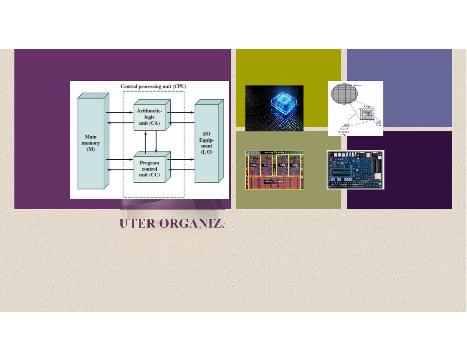
◼ von Neumann architecture is a simple structure, capable of executing
any kind of program, given a properly programmed control unit,
without the need of hardware modification ◼ three key concepts:
◼ Data and instructions are stored in a single read-write memory
◼ The contents of this memory are addressable by location
◼ Execution occurs in a sequential
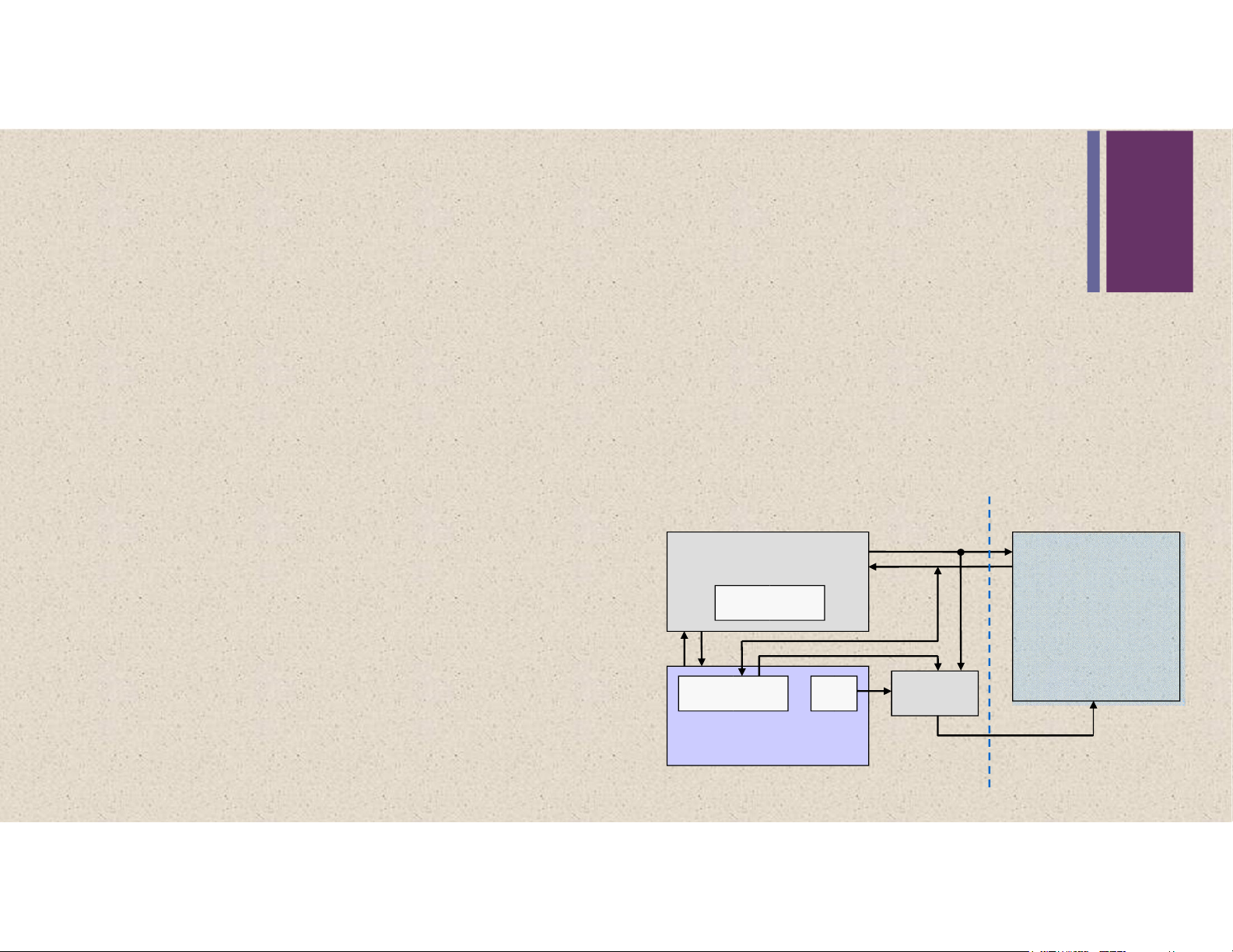
fashion (unless explicitly modified) Processor or Memory Central processing unit
from one instruction to the next Datapath Data Data Registers
A control unit (control path) featuring a and Instructions
program counter for controlling program execution Instruction Address PC Address register register
An arithmetic and logic unit (ALU) also Control path
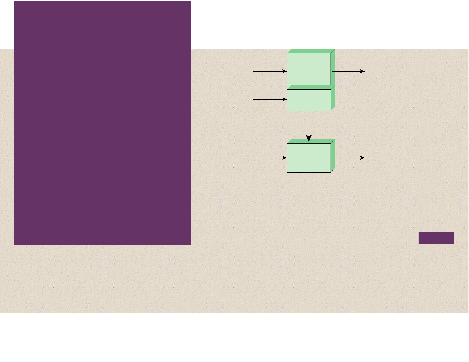
called data path for program execution lOMoAR cPSD| 58605085 + Hardware and Software (a) Programming in hardware Approaches Sequence of arithmetic Data Results and logic functions Figure Instruction Instruction 3.1 codes interpreter Control signals General-purpose arithmetic Data Results and logic functions
( b) Programming in software
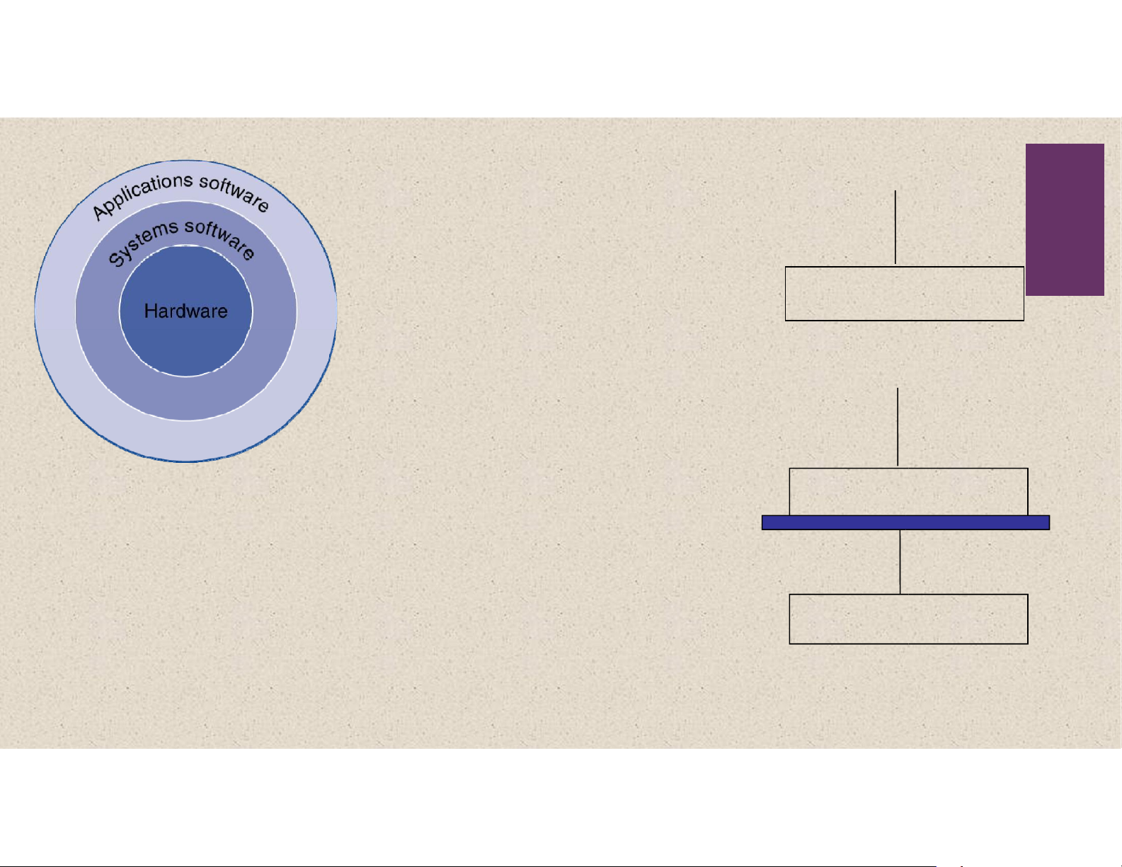
Hardware and Software Approaches Levels of Representation High Level Language Program lOMoAR cPSD| 58605085 temp = v[k]; v[k] = v[k+1];
v[k+1] = temp; Compiler 7 lw $15, 0($2) lw $16, 4($2) sw $16, 0($2) sw $15, 4($2) Assembly Language
0000 1001 1100 0110 1010 1111 0101 1000 Program
1010 1111 0101 1000 0000 1001 1100 0110
1100 0110 1010 1111 0101 1000 0000 1001
0101 1000 0000 1001 1100 0110 1010 1111 Assembler Machine Language ° Program °
Machine Interpretati o Control Signal Specification lOMoAR cPSD| 58605085 +
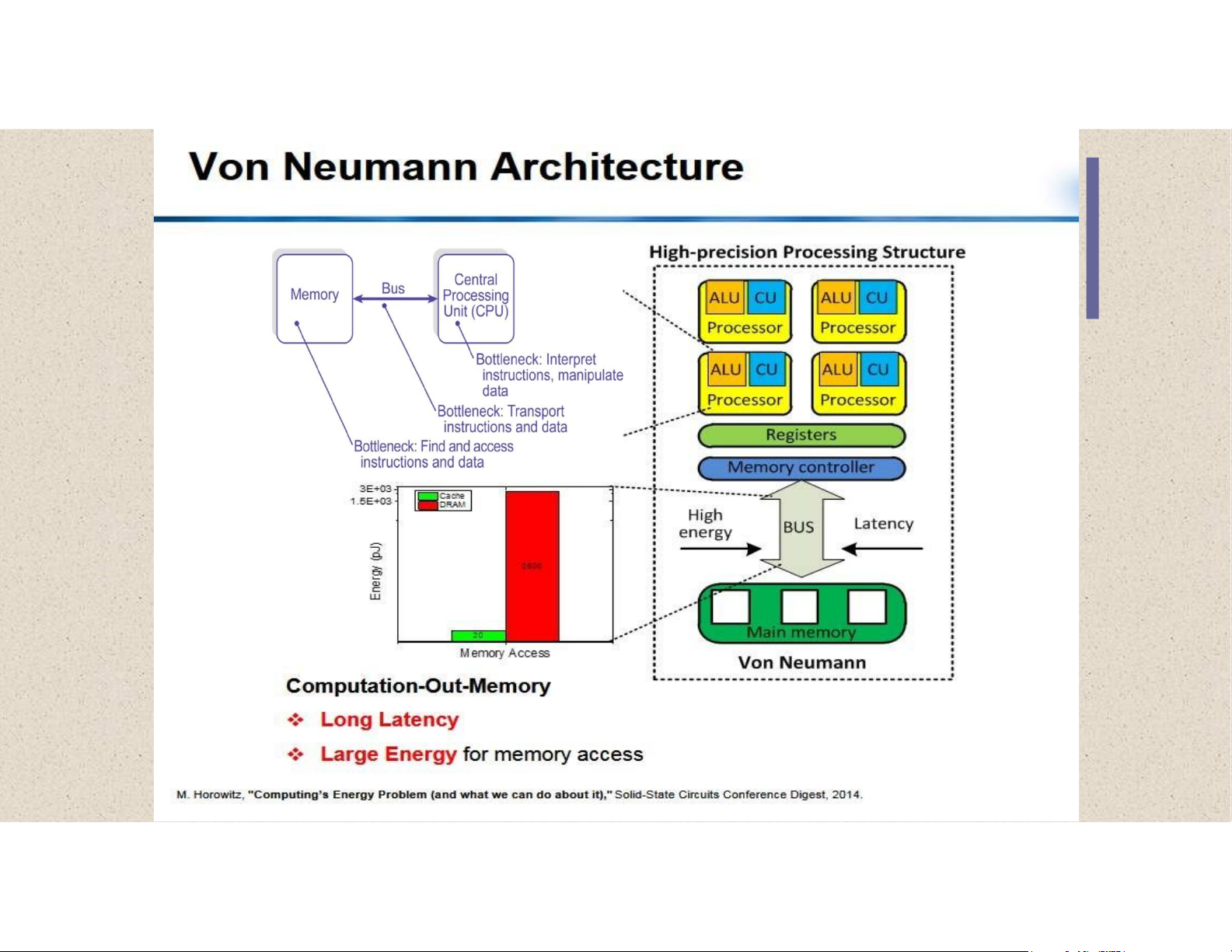
Bottlenecks in VN Architecture lOMoAR cPSD| 58605085
The Von Neumann Computer 8 ◼ Advantage: ◼ Simplicity. ◼
Flexibility: any well coded program can be executed ◼ Drawbacks: ◼
Speed efficiency: Not efficient, due to the sequential program
execution (temporal resource sharing). ◼
Resource efficiency: Only one part of the hardware resources is
required for the execution of an instruction. The rest remains idle. ◼
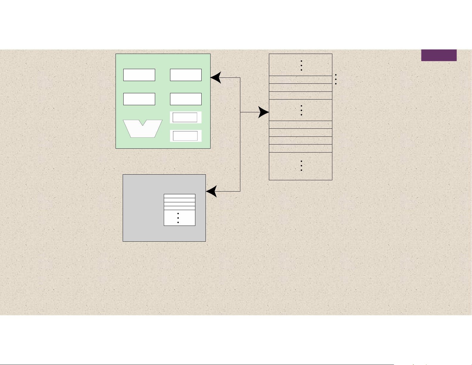
Memory access: Memories are about 5 times slower than the processor CPU Main Memory lOMoAR cPSD| 58605085 0 System 1 2 PC Bus MAR Instruction Instruction IR Instruction MBR I/O AR Data Execution unit I/O BR Data Data Data I/O Module n – 2 n – 1 PC = Pr ogram counter Buffers IR = Ins truction register
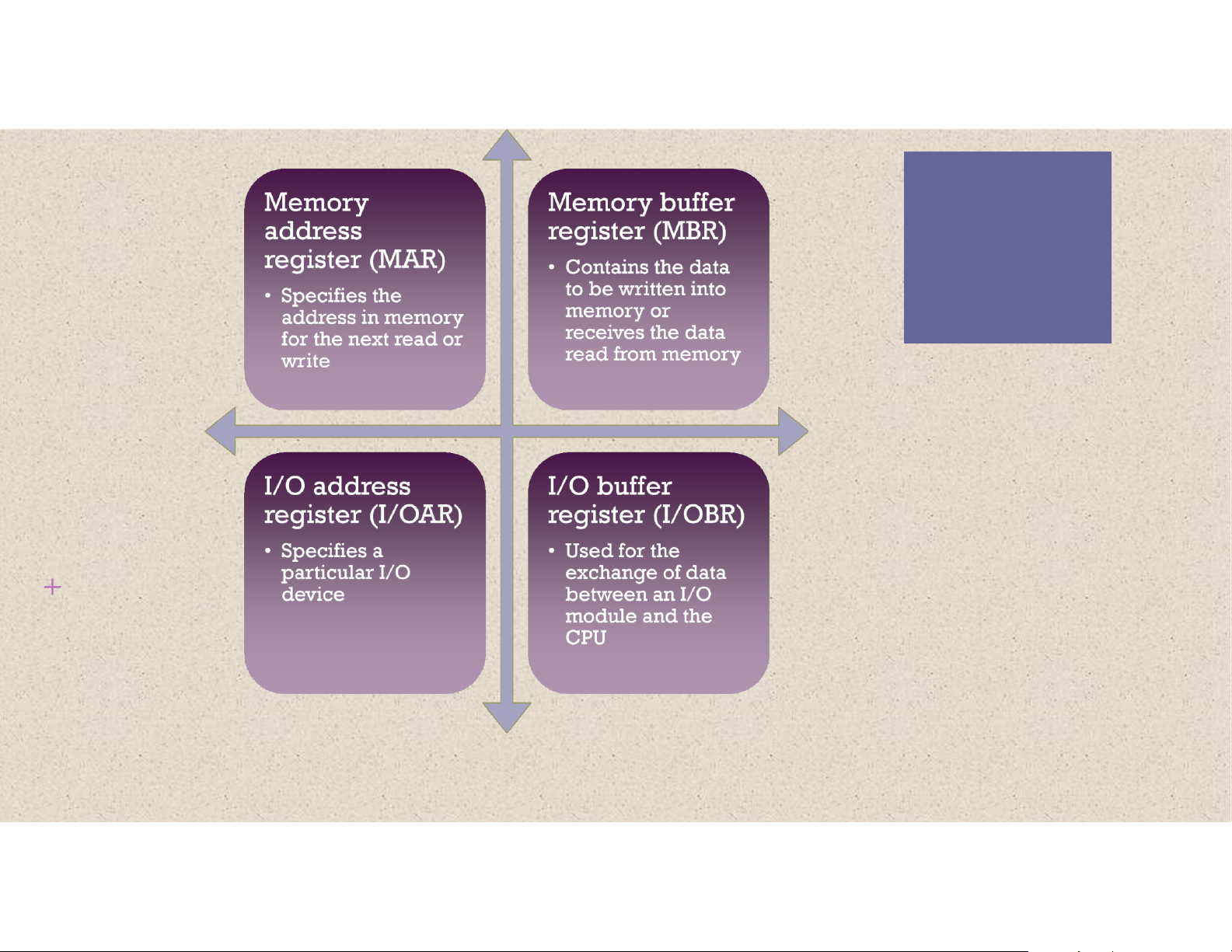
MAR = Memory address register
MBR = Memory buffer register
I/O AR = Input/output address register
I/O BR = Input/output buffer register
Figure 3.2 Computer Components: Top-Level View lOMoAR cPSD| 58605085 MEMORY MAR lOMoAR cPSD| 58605085 MBR lOMoAR cPSD| 58605085 lOMoAR cPSD| 58605085 + Fetch Execute Cycle
At the beginning of each instruction cycle
◼ The processor fetches an instruction from memory
◼ The program counter (PC) holds the address of the instruction to be fetched next
◼ The processor increments the PC after each instruction fetch so that it will
fetch the next instruction in sequence
◼ The fetched instruction is loaded into the instruction register (IR)
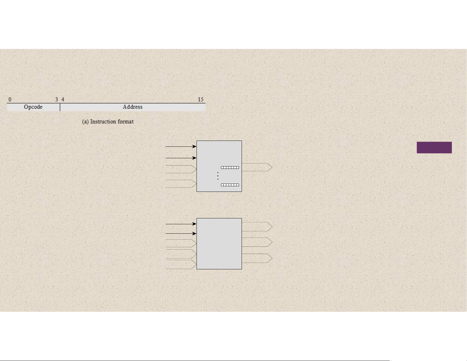
◼ The processor interprets the instruction and performs the required action lOMoAR cPSD| 58605085 0 3 4 15 Opcode Address (a) Instruction format 0 1 15 S Magnitude (b) Integer format
Program Counter (PC) = Address of instruction
Instruction Register (IR) = Instruction being executed
Accumulator (AC) = Temporary storage (c) Internal CPU registers 0001 = Load AC from Memory 0010 = Store AC to Memory 0101 = Add to AC from Memory (d) Partial list of opcodes lOMoAR cPSD| 58605085
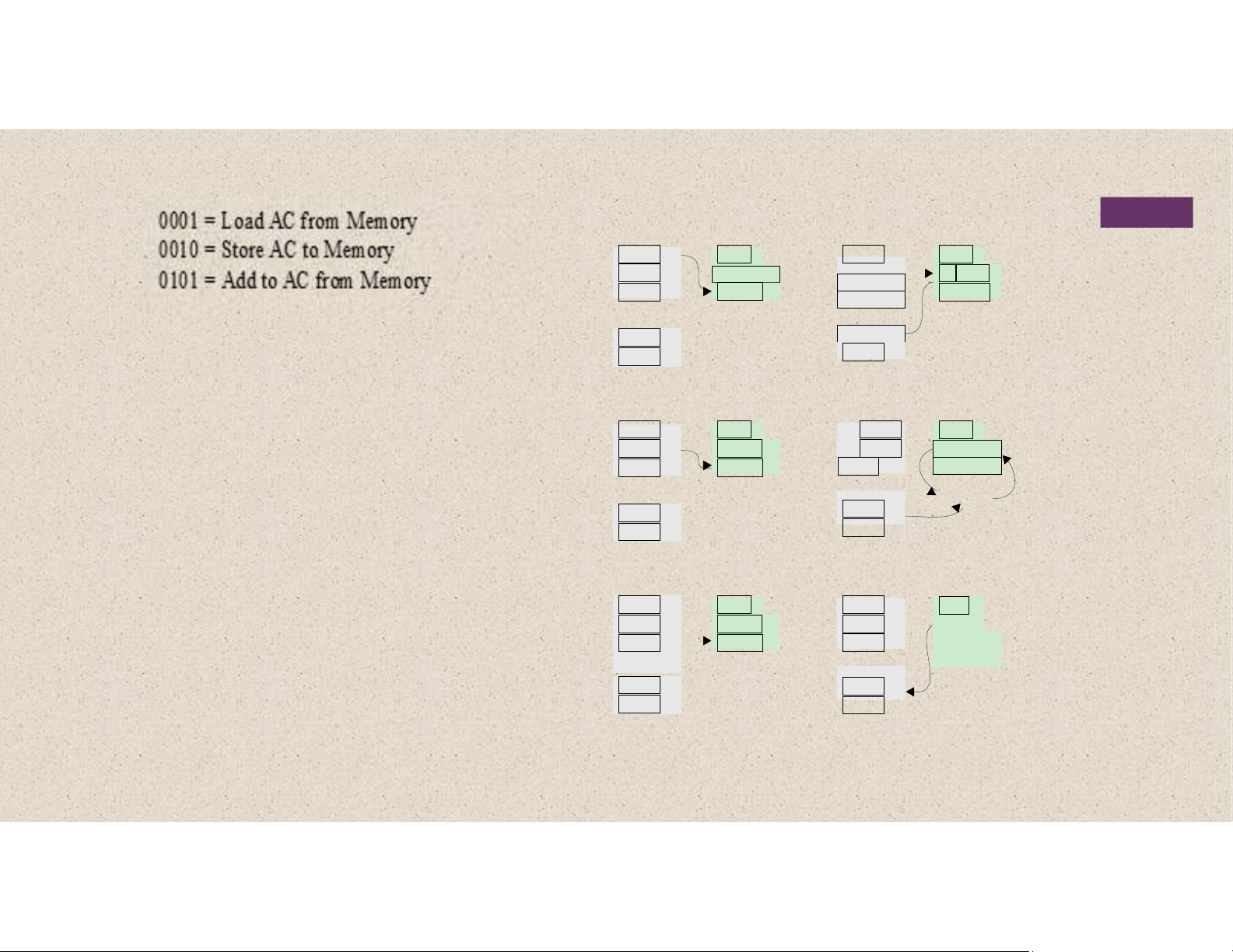
Figure 3.4 Characteristics of a Hypothetical Machine Memory CPU Registers Memory CPU Registers 300 1 9 4 0 3 0 0 PC 300 1 9 4 0 3 0 1 PC 301 5 9 4 1 AC 301 5 9 4 1 0 0 0 3 AC 302 2 9 4 1 1 9 4 0 IR 302 2 9 4 1 1 9 4 0 IR • • • 940 • 0 0 0 3 940 0 0 0 3 941 0 0 0 2 941 0 0 0 2 Step 1 Step 2 Memory CPU Registers Memory CPU Registers 300 1 9 4 0 3 0 1 PC 300 1 9 4 0 3 0 2 PC 301 5 9 4 1 0 0 0 3 AC 301 5 9 4 1 0 0 0 5 AC 302 2 9 4 1 5 9 4 1 IR 302 2 9 4 1 5 9 4 1 IR • • • 3 + 2 = 5 940 • 0 0 0 3 940 0 0 0 3 941 0 0 0 2 941 0 0 0 2 Step 3 Step 4 Memory CPU Registers Memory CPU Registers PC 300 1 9 4 0 3 0 2 PC 300 1 9 4 0 3 0 3 AC 301 5 9 4 1 0 0 0 5 AC 301 5 9 4 1 IR 302 2 9 4 1 2 9 4 1 IR 302 2 9 4 1 0 0 0 5 • • 2 9 4 1 • 940 • 0 0 0 3 940 0 0 0 3 941 0 0 0 2 941 0 0 0 5 Step 5 Step 6 lOMoAR cPSD| 58605085
Figure 3.5 Example of Program Execution
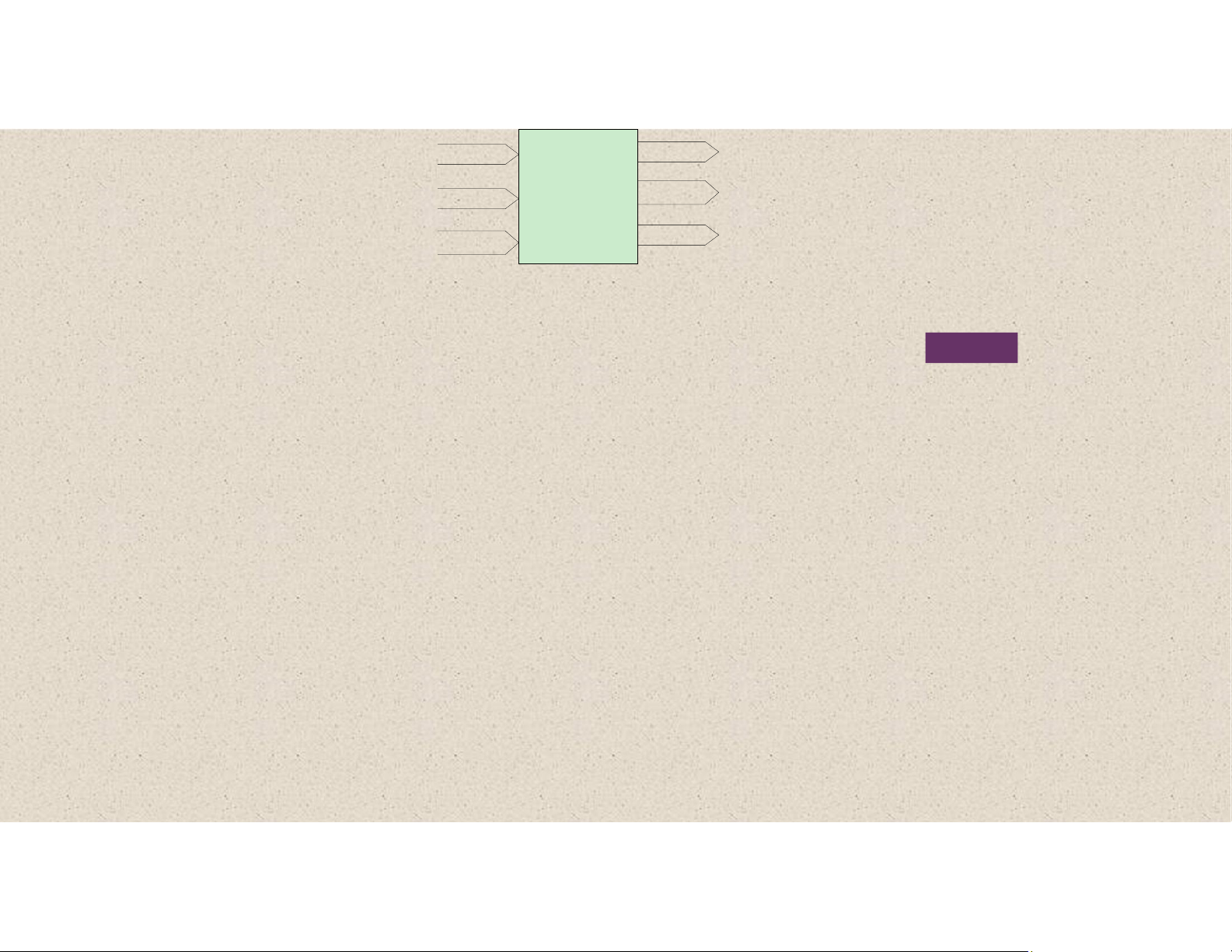
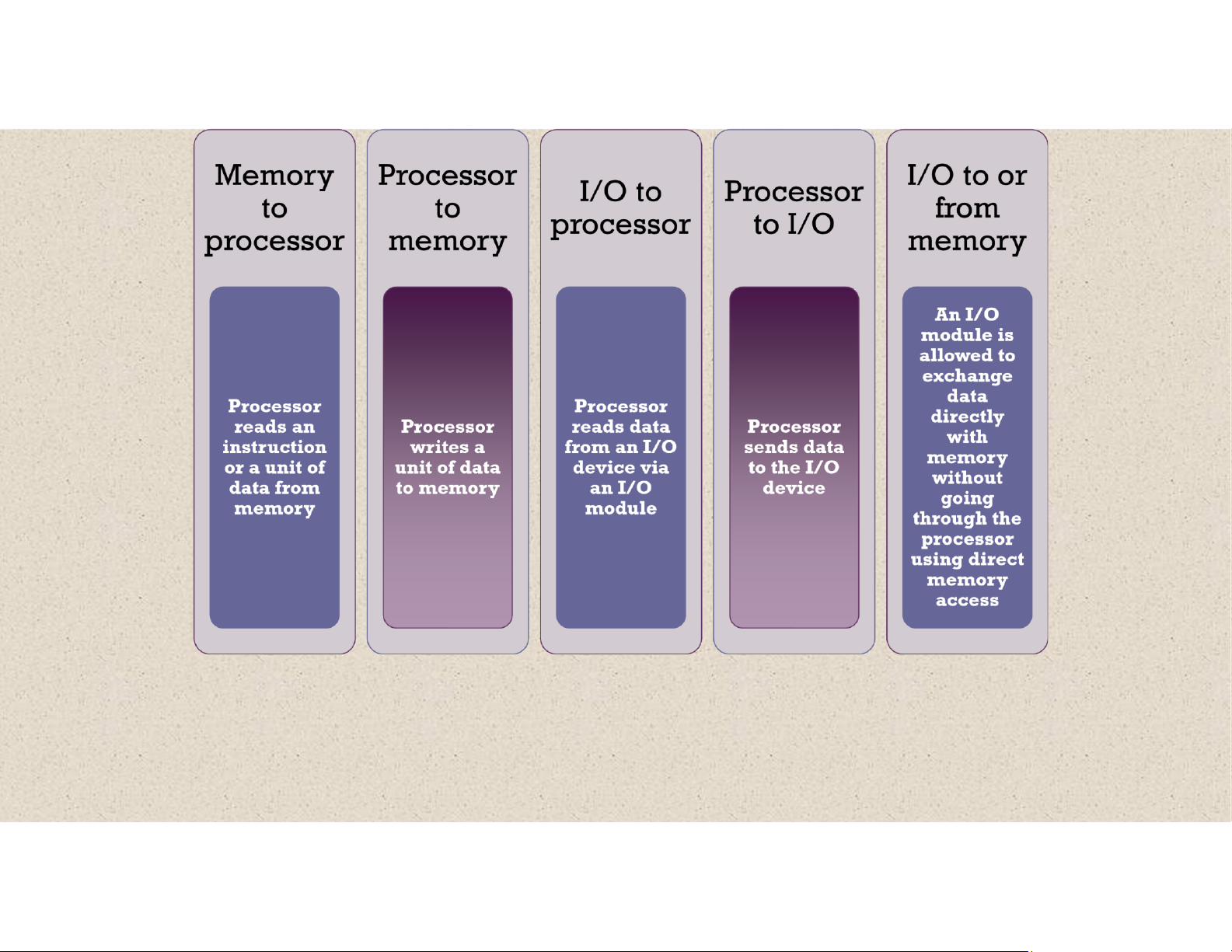
(contents of memory and registers in hexadecimal) Read Memory Write N Words 0 Data Address Data N – 1 Read I/O Module Internal Data Write External Address M Ports Data Internal Data Interrupt Signals External Data lOMoAR cPSD| 58605085 Instructions Address Control Data CPU Signals Interrupt Data Signals
Figure 3.15 Computer Modules
The interconnection structure must support the following types of transfers: lOMoAR cPSD| 58605085 lOMoAR cPSD| 58605085 A communication pathway Signals transmitted by any connecting two or more one device are available for devices reception by all other
•Key characteristic is that it is a devices attached to the bus shared transmission medium
•If two devices transmit during the
same time period their signals will I overlap and become garbled n n e
Typically consists of multiple communication lines Computer systems contain a t number of different buses •Each line is capable of that provide pathways
transmitting signals representing B c binary 1 and binary 0 between components at various levels of the e computer system hierarchy u t r s i System bus c •A bus that connects major The most common computer
computer components (processor, o memory, I/O) interconnection structures are based on the use of one o or more system buses n n lOMoAR cPSD| 58605085 Data Bus
◼ Data lines that provide a path for moving data among system modules
◼ May consist of 32, 64, 128, or more separate lines
◼ The number of lines is referred to as the width of the data bus
◼ The number of lines determines how many bits can be transferred at a time ◼ The width of the data bus is a key factor in determining overall system performance
© 2016 Pearson Education, Inc., Hoboken, NJ. All rights reserved. data bus read a word of data from ◼
◼ If the processor wishes to
Tài liệu liên quan:
-

Revise C++: Create Your First OOP Project Guide | Môn Computer Architecture and Organization Lab - Đại học Sư phạm Kỹ thuật Thành phố Hồ Chí Minh
99 50 -

Bài 1 - Lập trình điều khiển đèn giao thông và RTC | Môn Computer Architecture and Organization Lab - Đại học Sư phạm Kỹ thuật Thành phố Hồ Chí Minh
150 75 -

Final Report Môn Computer Architecture and Organization Lab | Đại học Sư phạm Kỹ thuật Thành phố Hồ Chí Minh
127 64 -

Summary of HDL Coding Techniques & Considerations | Môn Computer Architecture and Organization Lab - Đại học Sư phạm Kỹ thuật Thành phố Hồ Chí Minh
135 68 -

Giới thiệu về Dữ liệu, Thông tin và Cơ sở dữ liệu | Môn Computer Architecture and Organization Lab - Đại học Sư phạm Kỹ thuật Thành phố Hồ Chí Minh
100 50