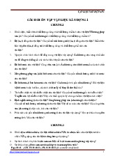
Fire resistance tests for nonloadbearing elements Part 4: Curtain walling — Part configuration - BSI Standards Publication | Trường Đại học Kiến trúc Hà Nội
CEN members are bound to comply with the CEN/CENELEC Internal Regulations which stipulate the conditions for giving this European Standard the status of a national standard without any alteration. Up-to-date lists and bibliographical references concerning such national standards may be obtained on application to the CEN-CENELEC Management Centre or to any CEN member. Tài liệu được sưu tầm giúp bạn tham khảo, ôn tập và đạt kết quả cao trong kì thi sắp tới. Mời bạn đọc đón xem !
Môn: Vật liệu xây dựng (HAU) 10 tài liệu
Trường: Trường Đại học Kiến trúc Hà Nội 335 tài liệu
Tác giả:


Preview text:
BS EN 1364-4:2014
Incorporating corrigendum June 2014
Fire resistance tests for non- loadbearing elements
Part 4: Curtain walling — Part configuration BS EN 1364-4:2014 BRITISH STANDARD National foreword
This British Standard is the UK implementation of EN 1364-4:2014. It
supersedes BS EN 1364-4:2007 which is withdrawn.
The UK participation in its preparation was entrusted by Technical
Committee FSH/22, Fire resistance tests to Subcommittee FSH/22/-/7,
Non loadbearing separating elements.
A list of organizations represented on this subcommittee can be
obtained on request to its secretary.
This publication does not purport to include all the necessary
provisions of a contract. Users are responsible for its correct application.
© The British Standards Institution 2014. Published by BSI Standards Limited 2014 ISBN 978 0 580 86415 5 ICS 13.220.50; 91.060.10
Compliance with a British Standard cannot confer immunity from legal obligations.
This British Standard was published under the authority of the
Standards Policy and Strategy Committee on 28 February 2014.
Amendments/corrigenda issued since publication Date Text affected 30 June 2014
Implementation of CEN correction notice 18 March 2014: Updated key in Figure 2 EUROPEAN STANDARD EN 1364-4 NORME EUROPÉENNE EUROPÄISCHE NORM February 2014 ICS 13.220.50; 91.060.10 English Version
Fire resistance tests for non-loadbearing elements - Part 4:
Curtain walling - Part configuration
Essais de résistance au feu des éléments non-porteurs -
Feuerwiderstandsprüfungen für nichttragende Bauteile -
Partie 4: Façades rideaux - Configuration partielle
Teil 4: Vorhangfassaden - Teilausführung
This European Standard was approved by CEN on 9 November 2013.
CEN members are bound to comply with the CEN/CENELEC Internal Regulations which stipulate the conditions for giving this European
Standard the status of a national standard without any alteration. Up-to-date lists and bibliographical references concerning such national
standards may be obtained on application to the CEN-CENELEC Management Centre or to any CEN member.
This European Standard exists in three official versions (English, French, German). A version in any other language made by translation
under the responsibility of a CEN member into its own language and notified to the CEN-CENELEC Management Centre has the same
status as the official versions.
CEN members are the national standards bodies of Austria, Belgium, Bulgaria, Croatia, Cyprus, Czech Republic, Denmark, Estonia,
Finland, Former Yugoslav Republic of Macedonia, France, Germany, Greece, Hungary, Iceland, Ireland, Italy, Latvia, Lithuania,
Luxembourg, Malta, Netherlands, Norway, Poland, Portugal, Romania, Slovakia, Slovenia, Spain, Sweden, Switzerland, Turkey and United Kingdom.
EUROPEAN COMMITTEE FOR STANDARDIZATION
C OM I TÉ EUR OP ÉEN DE NOR M ALI S ATI ON
EUR O P Ä IS C HES KOM I TE E F ÜR NOR M UNG
CEN-CENELEC Management Centre: Avenue Marnix 17, B-1000 Brussels © 2014 CEN
All rights of exploitation in any form and by any means reserved Ref. No. EN 1364-4:2014 E
worldwide for CEN national Members.
BS EN 1364-4:2014
EN 1364-4:2014 (E) Contents Page
Foreword .............................................................................................................................................................................4
Introduction ........................................................................................................................................................................5 1
Scope ..................................................................................................................................................................... 6 2
Normative references ......................................................................................................................................... 6 3
Terms and definitions ........................................................................................................................................ 7 4
Test equipment .................................................................................................................................................... 8 4.1
General testing principles ................................................................................................................................. 8 4.2
Furnace configuration ....................................................................................................................................... 9 4.3
Supporting floor .................................................................................................................................................. 9 5
Test conditions .................................................................................................................................................... 9 6
Test specimen .................................................................................................................................................. 10 6.1
Size ...................................................................................................................................................................... 10 6.2
Number of specimens ..................................................................................................................................... 10 6.3
Design ................................................................................................................................................................. 10 6.3.1
General ............................................................................................................................................................... 10 6.3.2
Standard configuration ................................................................................................................................... 11 6.3.3
Restraint of the specimen .............................................................................................................................. 11 6.3.4
Surfaces ............................................................................................................................................................. 12 6.3.5
Perimeter seal ................................................................................................................................................... 12 6.4
Construction ..................................................................................................................................................... 13 6.5
Verification ........................................................................................................................................................ 13 7
Installation of the test specimen .................................................................................................................. 13 7.1
General ............................................................................................................................................................... 13 7.2
Supporting floor ............................................................................................................................................... 13 7.2.1
Standard supporting floor ............................................................................................................................. 13 7.2.2
Non-standard supporting floor ..................................................................................................................... 13 7.3
Furnace closure ............................................................................................................................................... 14 7.4
Fixing of the framing system ........................................................................................................................ 14 8
Conditioning ...................................................................................................................................................... 14 9
Application of instrumentation ..................................................................................................................... 14 9.1
Thermocouples ................................................................................................................................................. 14 9.1.1
Furnace thermocouples (plate thermometers) ......................................................................................... 14 9.1.2
Unexposed face thermocouples ................................................................................................................... 14 2
BS EN 1364-4:2014
EN 1364-4:2014 (E) 9.2
Pressure ............................................................................................................................................................. 17 9.3
Radiation ............................................................................................................................................................ 17 10
Test procedure .................................................................................................................................................. 17 11
Performance criteria ........................................................................................................................................ 17 12
Test report .......................................................................................................................................................... 18 13
Field of direct application of test results .................................................................................................... 19 13.1
Rules for curtain walling type A .................................................................................................................... 19
13.1.1 General rules ..................................................................................................................................................... 19
13.1.2 Rules for the complete construction ........................................................................................................... 19
13.1.3 Framing system ................................................................................................................................................ 21
13.1.4 Spandrel panels ................................................................................................................................................ 24 13.2
Rules for curtain walling type B .................................................................................................................... 28 13.3
Perimeter seal .................................................................................................................................................... 28
13.3.1 General ................................................................................................................................................................ 28
13.3.2 Material ................................................................................................................................................................ 28
13.3.3 Width/depth ........................................................................................................................................................ 29
13.3.4 Fixing of the perimeter seal ........................................................................................................................... 29
13.3.5 Covering ............................................................................................................................................................. 29 13.4
Supporting floor ................................................................................................................................................ 29
Annex A (informative) Guidance on testing curtain walling – part configuration ........................................... 44 A.1
Standard configuration ................................................................................................................................... 44 A.1.1
General ................................................................................................................................................................ 44 A.1.2
Supporting floor ................................................................................................................................................ 44 A.1.3
Parts of a curtain walling ................................................................................................................................ 44 A.1.4
Specimen selection .......................................................................................................................................... 45 A.2
Test principles and requirements ................................................................................................................. 45 A.3
Fire from the inside .......................................................................................................................................... 47 A.3.1
General ................................................................................................................................................................ 47 A.3.2
Curtain walling type A ..................................................................................................................................... 47 A.3.3
Curtain walling type B ..................................................................................................................................... 47 A.3.4
Perimeter seal .................................................................................................................................................... 48 A.3.5
Fixing of the framing system ......................................................................................................................... 48 A.4
Fire from the outside ....................................................................................................................................... 48
Annex B (normative) Standard configurations ........................................................................................................ 51
Annex C (normative) Radiation calculation .............................................................................................................. 56
Annex D (normative) Field of direct application of test results for unitised construction ............................ 59 D.1
Rules for curtain walling type A .................................................................................................................... 59 D.1.1
General ................................................................................................................................................................ 59 D.1.2
Exposure conditions ........................................................................................................................................ 59 D.1.3
Rules for the complete construction ........................................................................................................... 59 D.1.4
Spandrel panels ................................................................................................................................................ 59 D.2
Rules for curtain walling type B .................................................................................................................... 59
Bibliography ..................................................................................................................................................................... 60 3
BS EN 1364-4:2014
EN 1364-4:2014 (E) Foreword
This document (EN 1364-4:2014) has been prepared by Technical Committee CEN/TC 127 “Fire safety in
buildings”, the secretariat of which is held by BSI.
This European Standard shall be given the status of a national standard, either by publication of an identical
text or by endorsement, at the latest by August 2014, and conflicting national standards shall be withdrawn at the latest by August 2014.
Attention is drawn to the possibility that some of the elements of this document may be the subject of patent
rights. CEN [and/or CENELEC] shall not be held responsible for identifying any or all such patent rights.
This document supersedes EN 1364 −4:2007.
This document has been prepared under a mandate given to CEN by the European Commission and the
European Free Trade Association, and supports essential requirements of 89/106/EEC.
According to the CEN/CENELEC Internal Regulations, the national standards organisations of the following
countries are bound to implement this European Standard: Austria, Belgium, Bulgaria, Croatia, Cyprus, Czech
Republic, Denmark, Estonia, Finland, Former Yugoslav Republic of Macedonia, France, Germany, Greece,
Hungary, Iceland, Ireland, Italy, Latvia, Lithuania, Luxembourg, Malta, Netherlands, Norway, Poland, Portugal,
Romania, Slovakia, Slovenia, Spain, Sweden, Switzerland, Turkey and the United Kingdom. 4
BS EN 1364-4:2014
EN 1364-4:2014 (E) Introduction WARNING
The attention of all persons concerned with managing and carrying out this fire resistance test is drawn to the
fact that fire testing can be hazardous and that there is a possibility that toxic and/or harmful smoke and gases
can be developed during the test. Mechanical and operational hazards can also arise during the construction
of the test elements or structures, their testing and disposal of test residues.
An assessment of all potential hazards and risks to health should be made and safety precautions should be
identified and provided. Written safety instructions should be issued. Appropriate training should be given to
relevant personnel. Laboratory personnel should ensure that they follow written safety instructions at all times. 5
BS EN 1364-4:2014
EN 1364-4:2014 (E) 1 Scope
This European Standard specifies a method for determining the fire resistance of parts of curtain walling and
of the perimeter seal. It examines the fire resistance to internal and external fire exposure of:
— the spandrel panel, i.e. downstand, upstand or a combination thereof, or — the perimeter seal, or
— the fixing of the framing system (anchoring) used to attach the curtain walling to the floor element, or — combinations thereof.
Results from tests according to this standard form the basis for classification of curtain walling type A (see 3.3 for definition).
For curtain walling type B (see 3.4 for definition) results may be used to determine fire resistance of parts of a
curtain walling to increase the field of application when previously tested to EN 1364-3. For intended
classification EW and for corner/faceted specimens EN 1364-3 should be used.
This European Standard does not cover double skin façades, over-cladding systems and ventilated façade
systems on external walls. It does not deal with the reaction to fire behaviour of curtain walling.
This standard is intended to be read in conjunction with EN 1363-1 and EN 1363-2 as well as EN 1364-3 for curtain walling type B. NOTE
Annex A gives informative guidance on the principles of testing parts of curtain walling and the test method.
2 Normative references
The following documents, in whole or in part, are normatively referenced in this document and are
indispensable for its application. For dated references, only the edition cited applies. For undated references,
the latest edition of the referenced document (including any amendments) applies.
EN 1363-1, Fire resistance tests - Part 1: General Requirements
EN 1363-2, Fire resistance tests - Part 2: Alternative and additional procedures
EN 1364-3, Fire resistance tests for non-loadbearing elements - Part 3: Curtain walling - Full configuration
(complete assembly)
EN 13119, Curtain walling - Terminology
EN 13501-1, Fire classification of construction products and building elements — Part 1: Classification using
data from reaction to fire tests
EN 13501-2, Fire classification of construction products and building elements — Part 2: Classification using
data from fire resistance tests, excluding ventilation services
EN 13830, Curtain walling - Product standard
EN ISO 13943, Fire safety - Vocabulary (ISO 13943) 6
BS EN 1364-4:2014
EN 1364-4:2014 (E)
3 Terms and definitions
For the purposes of this document, the terms and definitions given in EN 1363-1, EN 13119, EN 13830,
EN ISO 13943 and the following apply. 3.1 anchoring
see fixing of the framing system 3.2
associated wall construction
form of construction required to close the vertical side of the furnace (not part of the test specimen) 3.3
curtain walling type A
curtain walling without fire resistant glazing outside the spandrel area – fire resistant only in the spandrel area 3.4
curtain walling type B
curtain walling with fire resistant glazing outside the spandrel area - fully fire resistant curtain walling 3.5 downstand
special type of spandrel panel, hanging down from or located in front of the floor Note 1 to entry: See Figure A.2. 3.6 http: /qstandard.org/
fire-resistant glazing
glazing system consisting of one or more transparent or translucent panes with a suitable method of
mounting, with e.g. frames, seals and fixing materials, capable of satisfying the appropriate fire resistance criteria 3.7
fire resistant translucent or transparent spandrel panel
glass product, monolithic, laminated or insulating glass unit, manufactured by a particular manufacturer and
intended to be used as spandrel panel in curtain walling, which is CE marked based on a classification
according to EN 13501-2 in minimum one glazed construction Note 1 to entry:
The term “insulating” when used with “insulating glass unit” according to EN 1279–1, should not be
confused with the term “insulation” used in classification standard EN 13501–2. 3.8
fixing of the framing system
system used to attach the curtain wall to the loadbearing floor. It contains the brackets but not the anchor or
other devices used to fix the brackets to the floor 3.9 glazing materials
all materials used to glaze the fire resistant translucent or transparent spandrel panel into its frame 3.10
horizontally faceted curtain walling
curtain walling with an angle between horizontally adjacent infill panels at the common mullion (see Figure 1) 3.11
insulating glass unit (IGU)
glass product according to EN 1279–1 7
BS EN 1364-4:2014
EN 1364-4:2014 (E) 3.12 over-cladding system
protection system fixed to an external wall for weather protection 3.13 overrun time
time of fire resistance in minutes beyond the envisaged classification time, achieved in the test 3.14 perimeter seal see EN 13119 3.15 standard configuration
standard arrangement of curtain walling components in a test specimen 3.16 supporting floor
representation of a floor, forming part of the test construction, to allow the fixing of the test specimen of the
curtain walling and the installation of the perimeter seal 3.17 upstand
special type of spandrel panel, standing up from or located in front of the floor Note 1 to entry: See Figure A.2.
4 Test equipment
4.1 General testing principles
Table 1 defines which specific standard test configuration may be used for each part of the curtain walling
depending on the type of fire exposure and type of curtain walling.
The test equipment specified in EN 1363-1 and EN 1363-2 shall be used where applicable. 8
BS EN 1364-4:2014
EN 1364-4:2014 (E)
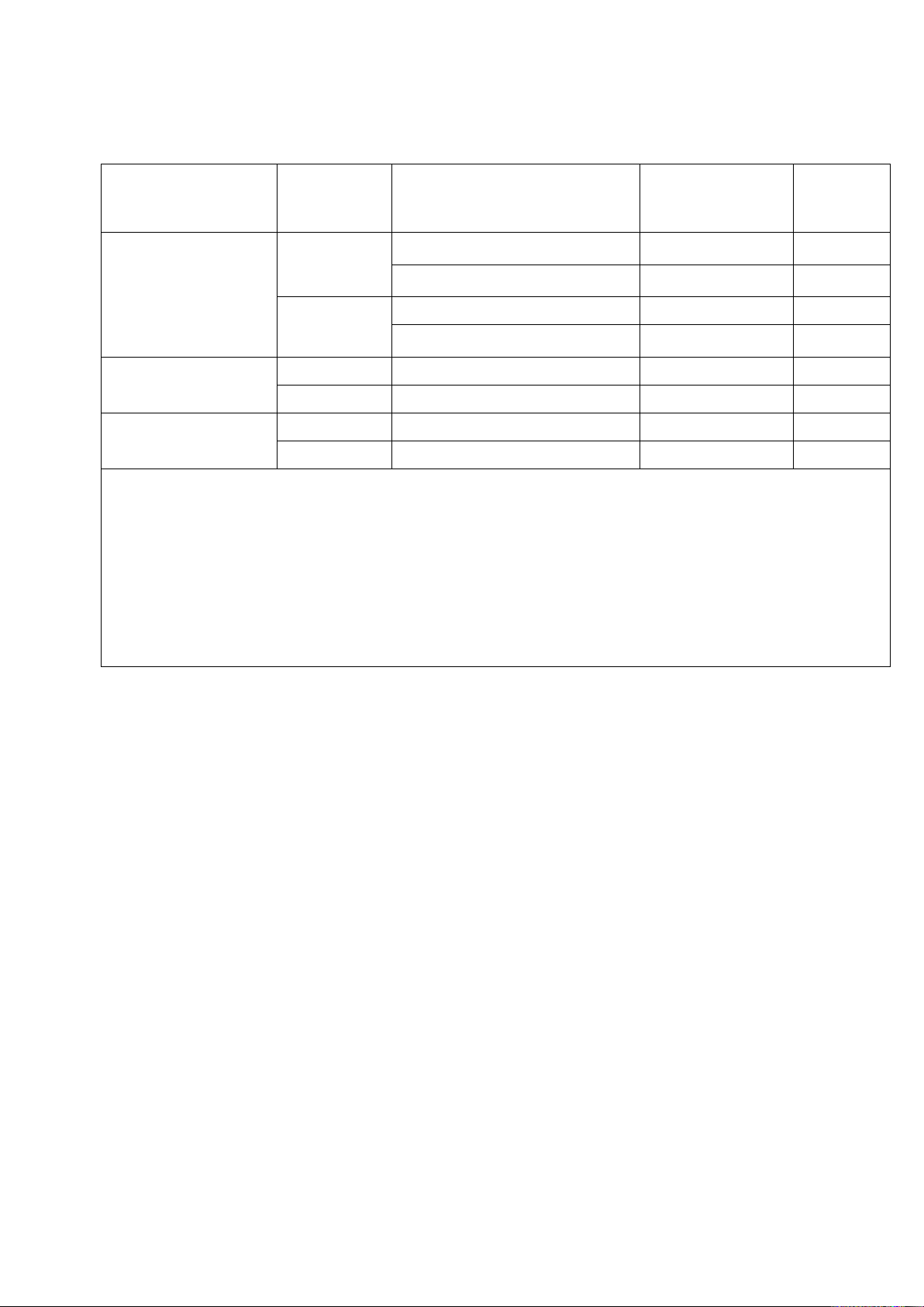
Table 1 — Standard test configurations and exposure conditions
Product / component Type of
Fire exposure / heating
Test configuration Surfaces
of curtain walling curtain conditions
(see Annex B) walling a
Internal (STC) + external (ef) b 1 S3 Spandrel panel A (upstand, downstand
Internal (STC) + external (STC) c 2 S3 or combinations Internal (STC) 3 S2, S3 thereof) B External (STC or ef) d 4 S1 A Internal (STC) 1, 5 - Perimeter seal B Internal (STC) 3, 5 - Fixing of the framing A Internal (STC) 1, 5 - system B Internal (STC) 3, 5 -
ef External fire curve as specified in EN 1363–2. STC
Standard temperature / time curve as specified in EN 1363–1.
For more information on the test configuration depending on the heating exposure and explanation, see Table A.1. a
For definition of type of curtain walling see 3.2 and 3.3 b
In case the requirement for the external fire exposure is the external fire curve as specified in EN 1363–2. c
In case the requirement for the external fire exposure is the standard temperature/time curve as specified in EN 1363–1. d
Depending on national requirements.
4.2 Furnace configuration
A floor or a wall furnace may be chosen. The minimum dimensions of the furnace are given in Figures B.1 to
B.5. For the installation of the specimen, wall or floor furnaces shall be modified, if necessary, to
accommodate the three-dimensional construction. The three dimensional construction includes the perimeter seal.
The test according to EN 1364-4 is performed on a three-dimensional specimen to allow an exposure of a
number of surfaces of the upstand/downstand (spandrel area) and incorporates a supporting floor, which
provides the support for the curtain walling.
4.3 Supporting floor
A supporting floor is provided as a base for the attachment of the fixing of the framing system and as a
location for the perimeter seal under examination. If information on the fire resistance of the curtain walling in
conjunction with a particular type of floor construction is required, such a construction shall be used, see 7.2.
5 Test conditions
The pressure conditions and the furnace atmosphere shall conform to those given in EN 1363-1, subject to a
nominal pressure of 20 Pa at the positions shown in Figures B.1 to B.5.
The heating conditions shall conform to those given in EN 1363-1 and/or EN 1363-2 for the test configuration
selected as given in Table 1. For details see Annex B. 9
BS EN 1364-4:2014
EN 1364-4:2014 (E) 6 Test specimen 6.1 Size
The size of the test specimen shall be as follows:
a) the height of the spandrel area as in practice (normally about 1 m),
b) if the width of the curtain walling in practice is less than 3 m, the specimen shall be full size as in practice, c)
if the width of the curtain walling in practice is larger than 3 m, the width of the specimen shall be not less than 3 m.
NOTE 1 A width larger than 3 m may be the result of single panels with a width of more than 3 m or the result of the
repetition of smaller construction units (mullion distance < 3m). NOTE 2
The height depends on national requirements.
Where the width of a single spandrel panel (upstand/downstand) is less than 3 m, at least 3 panels with the
mid panel at the maximum dimension shall be incorporated in the test specimen. Where the width of the panel
is greater than or equal to 3 m, at least 3 panels with the mid panel at the maximum width shall be
incorporated in the test specimen. The outer panels may be cut, subject to a minimum clearance between the
mullions at the boundary of the mid panel and the inner surface of the furnace of 200 mm.
The height h is the total of upstand and downstand (spandrel area).
If the height of the specimen is smaller than the vertical opening of the furnace, the furnace opening shall be
closed with a furnace closure according to 7.3.
6.2 Number of specimens
The performance of curtain walling or parts of curtain walling type A for internal and external exposure shall be
determined from a single test where the specimen is heated from both sides. For details see Annex B. For
curtain walling type B separate tests shall be performed for internal and external exposure.
NOTE Depending on national requirements the external exposure may be the external fire curve as specified in
EN 1363–2 or the standard temperature/time curve as specified in EN 1363–1. 6.3 Design 6.3.1 General The test specimen shall be:
— either fully representative of the construction intended for use in practice, including fixing of the framing
system, expansion joints, perimeter seals, any surface finishes and fittings which are essential and may
influence its behaviour in the test, or
— a standard configuration as defined in Annex B.
NOTE The use of a standard configuration allows the use of field of application rules to obtain the widest applicability
of the test result to other similar constructions.
The test specimen shall consist of parts of the curtain walling. It shall fully represent the construction on which
information is required. For use of field of application rules, one of the standard configurations given in
Table 1 as described in Annex B shall be used, see Clause 13. The test specimen shall consist of: 10
BS EN 1364-4:2014
EN 1364-4:2014 (E) — the curtain walling part, — the perimeter seal and
— the fixing of the framing system.
If the scope of the test is the perimeter seal and movement capability is intended to be considered (see A.3.4) the fixing may be omitted.
All design features which influence fire resistance performance shall be included. If the scope of the test
includes an assessment of the fixing of the framing system additional load may be required to take account of
the part of the curtain walling not included in the test. 6.3.2
Standard configuration 6.3.2.1 General
A straight test specimen shall comprise a section of the curtain walling with minimum two mullions or two
vertical joints between panels in case of systems without frame or mullions, fully exposed to the fire, see
Figure 2. In case a T-connection and/ or cross connection is intended to be included these shall be located in the heated area.
A transom shall be used on top and bottom of the spandrel panel except it is the intention of the test to
demonstrate the performance of panels not fixed on top or bottom.
A faceted specimen shall comprise minimum four sections of the curtain walling forming minimum one corner
of 90 degrees and two angles of 135 degrees, all sections with a minimum width of 500 mm, minimum three
sections with a width of minimum 1000 mm, see Figures 3A to 3D for examples. Two such specimens may be
combined to a specimen forming two corners of 90 degrees and two angles of 135 degrees, see Figures 3E and 3F for examples.
In case a transom is located in front of the floor slab in practice the test specimen shall also contain a transom
in front of the supporting floor. Such a transom is not considered being part of the perimeter seal but part of the framing.
A supporting floor shall be used for standard configurations 1, 2, 3 and 5. The design of the standard
supporting floor is given in 7.2.1. 6.3.2.2
Test configuration for curtain walling type A
The test specimen shall be heated from both sides at the same time. Depending on the requirements for the
external exposure the heating of conditions of the standard temperature/time curve as specified in EN 1363-1
are maintained on one side only or on both sides of the specimen – for details see Figures B.1 and B.2. 6.3.2.3
Test configuration for curtain walling type B
The test specimen shall be heated only from one side. In standard configurations for curtain walling type B the
furnace closure or fire-resistant glazing may be positioned directly beneath the upstand/downstand. For the furnace closure see 7.3.
For details see Figures B.3 and B.4. 6.3.3
Restraint of the specimen
The test specimen shall be fixed to the supporting floor using the fixing of the framing system (anchoring) of
the mullions as in practice. The mullions shall not be fixed at the lower end but may be fixed additionally to the 11
BS EN 1364-4:2014
EN 1364-4:2014 (E)
furnace frame on the upper end. The mullions may be fixed by spigot to simulate the situation that the
mullions abut each other in front of the floor in practice.
In case of external fire exposure (test specimen without supporting floor, standard configuration 4 according to
Figure B.4) the mullions shall be fixed to the furnace frame at the top of the specimen.
Both vertical edges shall be unrestrained. The furnace closure on the free edge between the associated wall
construction or furnace frame and the mullions, e.g. a mineral wool packing, shall allow unrestrained
movement of the mullions (see Figure 4).
The bottom edge of the test specimen shall be unrestrained. The furnace closure below the test specimen
shall allow unrestrained extension/movement of the mullions and the spandrel panel.
At the top of the specimen a mineral wool packing shall be placed so that the top edge of the test specimen is unrestrained.
In case no fixing of the framing system is used for a test of the perimeter seal (standard configuration 5
according to Figure B.5 but without fixing of the framing system) the mullions shall be fixed to a frame at top
and bottom. The edges of the spandrel panel shall remain unrestrained. 6.3.4 Surfaces
For definition of the surfaces for the installation of the thermocouples see Figure 5. The numbering of the
surfaces is the same as that used in EN 1364-3.
NOTE Surface S2 is the external surface of the curtain walling. 6.3.5 Perimeter seal 6.3.5.1
Test configuration/conditions regarding seal width and depth 6.3.5.1.1 Mineral wool
Where a seal with constant depth but variable joint width is considered, it shall be tested at maximum nominal
joint width. The degree of initial compression (%) exerted on the seal by the joint width as well as the direction
of the compression (see Figure 17) shall be recorded.
In case mineral wool is used as backing material (e.g. for membrane forming coatings or sealants) variations
of the mineral wool may be used within one test specimen provided the length of the seal with a particular
backing material is minimum the same as the distance between two mullions and it is located such that the
splice between different backing materials is not located in the area of the mullion. 6.3.5.1.2
Membrane forming coatings
The test shall be carried out using the minimum thickness (minimum of tolerance band for the nominal
thickness) of the membrane, minimum depth of mineral wool (or other backfilling material), maximum width
and minimum overlap at the substrate for the intended fire resistance performance. When a primer is part of
the system, it shall be included in the test. Each primer shall be tested separately. 6.3.5.1.3
Compressible strips (including composite)
Where only one seal depth is intended to be specified for all joint widths the maximum intended nominal joint
width shall be used. If the seal depth varies with the joint width a test shall be conducted at the maximum
nominal joint width for each related seal depth specified by the manufacturer. 12
BS EN 1364-4:2014
EN 1364-4:2014 (E) 6.3.5.1.4
Elastomeric strips
The test shall be carried out using the minimum thickness (minimum of tolerance band for the nominal
thickness) of the strip, maximum joint width and minimum overlap at the substrate. When a primer is part of
the system it shall be included in the test. Each primer shall be tested separately. 6.3.5.1.5 Sealants
Where only one seal depth, with a specified combination of sealant to backing material thickness, is intended
to be specified for all joint widths the maximum intended nominal joint width shall be used. If the thickness of
the sealant or the backing material varies with the joint width a test shall be conducted at the maximum
nominal joint width for each related seal depth specified by the manufacturer. 6.3.5.2
Test conditions regarding movement
In case movement capability is intended to be considered the fire test shall be commenced at maximum
extension/shear of the perimeter seal.
NOTE For further information on test requirements for perimeter seals in case of required movement capability see A.3.4. 6.4 Construction
The test specimen shall be constructed as described in EN 1363-1, subject to deviating rules given in this standard.
In case a component of the curtain walling is cut all open gaps shall be closed using material of class A1 according to EN 13501-1. 6.5 Verification
Verification of the test specimen shall be carried out as described in EN 1363-1.
7 Installation of the test specimen 7.1 General
The test specimen shall be fitted to the supporting floor by means of the fixing of the framing system that are used in practice, see 7.2.
7.2 Supporting floor 7.2.1
Standard supporting floor
The standard supporting floor shall have a minimum thickness of 150 mm and minimum width of 500 mm for
straight specimens. For faceted specimens the minimum width shall be 200 mm (see Figure 6). The floor shall
be made of reinforced concrete or made of reinforced aerated concrete and shall be restrained at three sides. 7.2.2
Non-standard supporting floor
Any floor construction as in practise may be used. The results of the test are limited to that floor construction
only (no field of direct application concerning floor constructions). 13
BS EN 1364-4:2014
EN 1364-4:2014 (E)
7.3 Furnace closure
The furnace closure at the bottom end of the test specimen (see Figures B.3 to B.5) shall be made of a
mineral wool packing of approximately 250 mm thickness and a density of maximum 50 kg/m3 allowing
movement of the specimen to a similar extent as in practice. Additional fixing to prevent falling out of the
mineral wool packing is permitted.
The furnace closure at the top end of the test specimen (see Figures B. 1, B.2 and B.4) shall be made of a
mineral wool packing. Intumescent material may be added on top of the mineral wool packing to avoid a gap
opening in case the specimen sags.
For a test of a curtain walling type B the assembly shall be installed with an additional closure at the bottom
(see Figures B.3 and B.4). Where only the perimeter seal or the fixing of the framing system is tested, the
additional closure shall also be used (see Figure B.5).
7.4 Fixing of the framing system
The fixing shall be done as in practice, subject to the exception given in 6.3.1 for testing perimeter seals. 8 Conditioning
The test construction shall be conditioned in accordance with EN 1363-1.
9 Application of instrumentation 9.1 Thermocouples 9.1.1
Furnace thermocouples (plate thermometers)
Plate thermometers shall be provided in accordance with EN 1363-1 except that the thermometers may be
placed closer than 450 mm to any furnace surface. There shall be at least one plate thermometer on each
heated side every metre length of the specimen or one per 1,5 m2 exposed surface area per heated side of
the test specimen. The higher resulting number of plate thermometers shall apply. Plate thermometers T1 and
T2 shall be oriented so that side ‘A’ faces the back wall of the furnace, plate thermometers T3 and T4 shall be
oriented so that side ‘A’ faces the floor of the furnace (see Figures B.1 to B.5). For details of location of plate
thermometers see Annex B and Figures 9 and 10 for faceted specimens.
The set of thermocouples, designated as T1 in the figures of Annex B, is used for furnace control. The
thermocouples designated T2 in the figures of Annex B are for information only. 9.1.2
Unexposed face thermocouples 9.1.2.1 General
The general rules for the attachment and exclusion of unexposed face thermocouples given in EN 1363-1 shall apply.
For internal exposure, if it is not necessary to evaluate the insulation criteria for Surfaces 2 and 5 then the thermocouples may be omitted. 9.1.2.2
Mean temperature rise
The mean temperature rise shall be measured on Surfaces 1, 2 and 3. 14
BS EN 1364-4:2014
EN 1364-4:2014 (E)
The mean temperature rise shall be measured on each discrete infill / panel area ≥ 0,1 m2 by means of one
thermocouple per 1,5 m2, subject to minimum two thermocouples per discrete area. The thermocouples shall
be located in two opposite corners at a distance of approximately a third of the width and approximately a third
of the length of the heated part of the discrete area, see Figure 7. If due to the size of the discrete area a third
thermocouple is required it shall be positioned close to the centre of the discrete area. Records from all
discrete areas of the same type shall be used for calculating the mean temperature rise. Thermocouples shall
not be positioned closer than 100 mm from any discrete area that is not being evaluated for insulation.
For discrete areas which are non-uniform, i.e. those which have surface corrugations or ribs, the temperature
of each area/surface type shall be monitored to determine the mean temperature rise.
As there are no evaluation criteria for the perimeter seal, the mean temperature rise is not measured. 9.1.2.3
Maximum temperature rise 9.1.2.3.1 Surface 1
Thermocouples shall be applied to Surface 1 as follows and given in Figure 2.A for straight specimens and
Figure 8 for faceted specimens:
— Thermocouple 1A - 20 mm below the soffit of the upper transom at mid width of the panel;
— Thermocouple 1B - on a mullion surface, parallel to the furnace opening, 20 mm below the soffit of the
upper transom or the upper edge of the uppermost panel;
— Thermocouple 1C - at the junction of a mullion and the lower transom or 20 mm above the bottom end of the mullion;
— Thermocouple 1F - at mid way between two mullions at the lower transom or 20 mm above the lower edge of the lowest panel;
— Thermocouple 1G - on a mullion surface, parallel to the furnace opening, at mid way between two transoms;
— Thermocouple 1H – at mid-height of the panel with the largest area, 20 mm from the mullion for each type of spandrel panel;
— Thermocouple 1J – in the top corners of the panel with the largest area, for each type of spandrel panel,
20 mm from the mullion and the transom. 9.1.2.3.2 Surface 2
Thermocouples shall be applied to Surface 2 as follows and given in Figure 2.B for straight specimens and
Figures 7 and 10 for faceted specimens:
— Thermocouple 2A – level with the soffit of the supporting floor at mid width of the panel;
— Thermocouple 2B – on a mullion surface, parallel to the furnace opening, level with the soffit of the supporting floor;
— Thermocouple 2C – at the junction of a mullion and the lower transom;
— Thermocouple 2F – at mid way between two mullions on the lower transom or 20 mm above the lower edge of the lowest panel;
— Thermocouple 2G – on a mullion surface, parallel to the furnace opening, at mid way between two transoms; 15
BS EN 1364-4:2014
EN 1364-4:2014 (E)
— Thermocouple 2H – at mid-height of the panel with the largest area, 20 mm from the mullion, for each type of spandrel panel;
— Thermocouple 2J – in the top corners of the panel with the largest area, for each type of spandrel panel,
20 mm from the mullion and the transom. 9.1.2.3.3 Surface 3
Thermocouples shall be applied to Surface 3 as follows and given in Figures 3.C and 3.D for straight
specimens and Figures 10 and 11 for faceted specimens:
— Thermocouple 3A: on the panel at mid way between two mullions, 20 mm up from top of the supporting floor;
— Thermocouple 3B: on a mullion surface, parallel to the furnace opening, 20 mm up from top of the supporting floor;
— Thermocouple 3C: on a mullion surface, 90° to the furnace opening, 20 mm up from top of supporting floor. 9.1.2.3.4 Perimeter seal
For the determination of the maximum temperature rise, thermocouples shall be applied to the perimeter seal as follows (see Figure 12A):
— Thermocouple HV: at the top surface of the seal, centrally between the mullions and centrally across the perimeter seal;
— Thermocouple HW: at the top surface of the seal 20 mm from a mullion centrally across the perimeter seal;
— Thermocouple HV1: at the top surface of the seal located at quarter point between the mullions at the
position where the seal abuts the floor;
— Thermocouple HV2: at the top surface of the seal located at quarter point between the mullions at the
position where the seal abuts the panel;
— Thermocouple HZ: if there is a splice in the gap seal this thermocouple shall be positioned adjacent to the
gap seal at a position 20 mm from the splice;
— Thermocouple HT – in case a transom is located in front of the supporting floor or so close to the
supporting floor, that it is in contact with the perimeter seal, on top of the transom at mid length and mid width (see Figure 12B). 9.1.2.3.5
Roving thermocouple
A roving thermocouple shall be provided for measuring maximum temperature at any point. 9.1.2.3.6
Additional thermocouples
Any further thermocouples used to provide additional information (e.g. for measuring temperatures inside the
wall) shall be attached without damaging the specimen. 9.1.2.4
Thermocouples on the fixing of the framing system
Thermocouples shall be provided to measure the temperature of any fixings used to attach the curtain walling to the supporting floor. 16
BS EN 1364-4:2014
EN 1364-4:2014 (E) 9.2 Pressure
Furnace pressure shall be measured as detailed in EN 1363-1. During the test, the pressure shall be
measured at a point 100 mm below the supporting floor (internal fire exposure) or 100 mm below the top of
the specimen (external fire exposure) at the points indicated in the figures in Annex B. 9.3 Radiation
If radiation is to be measured for curtain walling type A, it shall be done according to EN 1363-2. Radiometers
shall be positioned opposite the geometric centre of that part of the unexposed area of the test specimen that
is heated. The distance of the radiometer may be decreased compared to the requirement given in EN 1363-2
to increase the accuracy of the measurement. If the distance has been decreased the results shall be re-
calculated for a distance of 1 m. Deviating from the rules given in Annex B the spandrel panel shall be
extended in height such that Surface 3 has the height of the upstand as in practice, subject to minimum
500 mm. If radiation is to be measured the test specimen shall be uniform across its width, i.e. the same type
of panel used in all discrete areas. NOTE
For curtain walling type B tests according to this standard are not suitable for determination of radiation.
10 Test procedure
The test shall be carried out using the equipment and according to the procedures specified in EN 1363-1
and, if applicable, EN 1363-2.
11 Performance criteria
The criteria by which the performance of the test specimen is judged are given in EN 1363-1. The results for
insulation and integrity shall be presented separately for external exposure, internal exposure and the
perimeter seal, as shown in Table 2.
In addition to the integrity criteria given in EN 1363-1 the spandrel panel shall remain in place over its full
height of the test specimen (h as shown in Figures B.1 and B.2) for curtain walling type A.
Performance with respect to insulation is assessed for different parts of the test specimen, depending on the
test configuration selected according to Table 1. Figures 3, 7, 8, 9, 11 and 13 show the groups of
thermocouples to be used for this purpose for one or more of the following:
a) unexposed internal face of the spandrel panel above the supporting floor, Surface 3 (curtain walling type A),
b) unexposed internal face of the spandrel panel above the supporting floor, Surface 3, and external face,
Surface 2 (curtain walling type B – internal exposure), c)
unexposed internal face of the spandrel panel, Surface 1 (curtain walling type B – external exposure),
d) unexposed surface of the perimeter seal.
The temperature of the fixing of the framing system shall be measured and recorded.
Measurement of the temperature of the fixing of the framing system is not a classification criterion but may be
used in evaluating the possible reduction in structural strength of the fixing.
Performance with respect to radiation is assessed following the procedure given in Annex C. 17
BS EN 1364-4:2014
EN 1364-4:2014 (E)
Other observations as specified in EN 1363-1 shall be made and recorded. Falling parts from the curtain
walling construction may be recorded if required according to national regulations.
NOTE There is no performance criteria associated with falling parts.
Table 2 — Performance criteria Type of Fire Component / Integrity Insulation Radiation curtain exposure Surface Cotton Gap Flaming Mean Maximum walling pad gauge temperature temperature rise rise A Internal + S3 Y – Y Y Y a Y external B Internal S2 Y Y Y Y Y a - b B Internal S3 – – Y Y Y a - b B Internal S5 Y - Y - - - B External S1 – Y Y Y Y a - b A, B Internal Perimeter seal Y Y Y – Y - a For each type of panel b
For classification EW of a curtain walling type B or components of it results from a test according to EN 1364–3 shall be used 12 Test report
In addition to the items required by EN 1363-1, the following shall also be included in the test report:
a) a reference that the test was carried out in accordance with EN 1364-4,
b) type of the curtain walling according to 3.2 or 3.3, c)
the type of specimen, i.e. straight or faceted;
d) test results identified in accordance with the performance criteria in Table 2: e) temperature curve used; f)
if relevant, the records of radiation measurement together with the panel dimensions used in the test and
the calculation for other panel dimensions according to Annex C, if applicable;
g) if required, the time when parts fell off from Surfaces S2 and S5 and their approximate size.
If during one test the internal and external exposure heating criteria have been satisfied, graphs and/or
tabulated results of measurements made during the whole test shall be given separately for each exposure condition. 18
Tài liệu liên quan:
-
Câu hỏi ôn tập Vật liệu xây dựng - XD2828 & XD2801 | Trường đại học kiến trúc Hà Nội
118 59 -
Tiện ích và Vật liệu Xây dựng: Đánh giá Hiệu quả Sử dụng | Trường đại học kiến trúc Hà Nội
99 50 -
Đề cương bài tập vật liệu công trình | Trường đại học kiến trúc Hà Nội
176 88 -
Câu Hỏi & Bài Tập Môn Vật Liệu Xây Dựng | Trường đại học kiến trúc Hà Nội
114 57 -
Giao Trình Vật Liệu Xây Dựng | Trường đại học kiến trúc Hà Nội
162 81