Giáo trình Ethernet Basics môn Thương mại điện tử | Trường Đại học Kinh Tế Quốc Dân
Giáo trình Ethernet Basics môn Thương mại điện tử | Trường Đại học Kinh Tế Quốc Dân. Tài liệu được sưu tầm giúp bạn tham khảo, ôn tập và đạt kết quả cao. Mời bạn đọc đón xem.
Môn: Thương mại điện tử căn bản 78 tài liệu
Trường: Trường Đại học Kinh Tế Quốc Dân 8.7 K tài liệu
Tác giả:


Preview text:
Ethernet Basics Rev. 02 Contents 1 Introduction 1
1.1 The OSI model . . . . . . . . . . . . . . . . . . . . . . . . . . . . . . . . . . . . . . 1
1.2 LAN . . . . . . . . . . . . . . . . . . . . . . . . . . . . . . . . . . . . . . . . . . . . 3 2 Ethernet 5
2.1 Introduction . . . . . . . . . . . . . . . . . . . . . . . . . . . . . . . . . . . . . . . 5
2.2 The physical implementations . . . . . . . . . . . . . . . . . . . . . . . . . . . . . 6
2.2.1 Implementations based on coax . . . . . . . . . . . . . . . . . . . . . . . . 7
2.2.2 Implementations based on twisted pair . . . . . . . . . . . . . . . . . . . . 7
2.2.3 Implementations based on fibre
. . . . . . . . . . . . . . . . . . . . . . . . 11
2.2.4 Wireless LAN . . . . . . . . . . . . . . . . . . . . . . . . . . . . . . . . . . . 11
2.2.5 Bluetooth . . . . . . . . . . . . . . . . . . . . . . . . . . . . . . . . . . . . . 14
2.3 The data link layer . . . . . . . . . . . . . . . . . . . . . . . . . . . . . . . . . . . . 16
2.3.1 Introduction . . . . . . . . . . . . . . . . . . . . . . . . . . . . . . . . . . . . 16
2.3.2 MAC address . . . . . . . . . . . . . . . . . . . . . . . . . . . . . . . . . . . 16
2.3.3 The Ethernet dataframe . . . . . . . . . . . . . . . . . . . . . . . . . . . . . 17
2.3.4 CSMA/CD . . . . . . . . . . . . . . . . . . . . . . . . . . . . . . . . . . . . . 18
2.3.5 CSMA/CA . . . . . . . . . . . . . . . . . . . . . . . . . . . . . . . . . . . . . 20
2.4 Structure elements for Ethernet . . . . . . . . . . . . . . . . . . . . . . . . . . . . 21
2.4.1 The hub . . . . . . . . . . . . . . . . . . . . . . . . . . . . . . . . . . . . . . 21 2.4.2 The switch
. . . . . . . . . . . . . . . . . . . . . . . . . . . . . . . . . . . . 22 2.5 IEEE802.1Q tagged frame
. . . . . . . . . . . . . . . . . . . . . . . . . . . . . . . 24
2.6 Power over Ethernet . . . . . . . . . . . . . . . . . . . . . . . . . . . . . . . . . . . 24 2.6.1 PSE
. . . . . . . . . . . . . . . . . . . . . . . . . . . . . . . . . . . . . . . . 25
2.6.2 PD . . . . . . . . . . . . . . . . . . . . . . . . . . . . . . . . . . . . . . . . . 25
2.6.3 Alternative A . . . . . . . . . . . . . . . . . . . . . . . . . . . . . . . . . . . 26
2.6.4 Alternative B . . . . . . . . . . . . . . . . . . . . . . . . . . . . . . . . . . . 26
2.7 VLAN . . . . . . . . . . . . . . . . . . . . . . . . . . . . . . . . . . . . . . . . . . . 28
2.7.1 Advantages of VLANs . . . . . . . . . . . . . . . . . . . . . . . . . . . . . . 28
2.7.2 Trunking . . . . . . . . . . . . . . . . . . . . . . . . . . . . . . . . . . . . . . 28
2.7.3 VLAN types . . . . . . . . . . . . . . . . . . . . . . . . . . . . . . . . . . . . 29
2.8 Network redundancy . . . . . . . . . . . . . . . . . . . . . . . . . . . . . . . . . . 30
2.8.1 Introduction . . . . . . . . . . . . . . . . . . . . . . . . . . . . . . . . . . . . 30
2.8.2 The Spanning Tree Protocol . . . . . . . . . . . . . . . . . . . . . . . . . . . 30
2.8.3 The Rapid Spanning Tree Protocol
. . . . . . . . . . . . . . . . . . . . . . . 30
2.8.4 Bridge Protocol Data Units (BPDUs)
. . . . . . . . . . . . . . . . . . . . . . 31
2.8.5 Multiple Spanning Tree Protocol (MSTP) . . . . . . . . . . . . . . . . . . . . 32
2.8.6 Media Redundancy Protocol . . . . . . . . . . . . . . . . . . . . . . . . . . . 32 Contents ii
2.8.7 Parallel Redundancy Protocol . . . . . . . . . . . . . . . . . . . . . . . . . . 32
2.9 Important additions . . . . . . . . . . . . . . . . . . . . . . . . . . . . . . . . . . . 32
2.9.1 LLDP . . . . . . . . . . . . . . . . . . . . . . . . . . . . . . . . . . . . . . . . 32
2.9.2 IEEE 802.1x . . . . . . . . . . . . . . . . . . . . . . . . . . . . . . . . . . . . 33
2.9.3 Link Aggregation with LACP to IEEE 802.3ad
. . . . . . . . . . . . . . . . . 34
2.10Industrial Ethernet . . . . . . . . . . . . . . . . . . . . . . . . . . . . . . . . . . . . 35 3 TCP/IP 37
3.1 Introduction . . . . . . . . . . . . . . . . . . . . . . . . . . . . . . . . . . . . . . . 37
3.2 The Internet Protocol (IP) . . . . . . . . . . . . . . . . . . . . . . . . . . . . . . . . 38
3.2.1 Introduction . . . . . . . . . . . . . . . . . . . . . . . . . . . . . . . . . . . . 38
3.2.2 The IP address . . . . . . . . . . . . . . . . . . . . . . . . . . . . . . . . . . 39
3.2.3 Routers and subnet masking . . . . . . . . . . . . . . . . . . . . . . . . . . 42
3.2.4 Subnetting . . . . . . . . . . . . . . . . . . . . . . . . . . . . . . . . . . . . 43
3.2.5 Classless Inter-Domain Routing
. . . . . . . . . . . . . . . . . . . . . . . . 44
3.2.6 Examples . . . . . . . . . . . . . . . . . . . . . . . . . . . . . . . . . . . . . 45
3.2.7 The IP packet . . . . . . . . . . . . . . . . . . . . . . . . . . . . . . . . . . . 46
3.2.8 IPv6 . . . . . . . . . . . . . . . . . . . . . . . . . . . . . . . . . . . . . . . . 48
3.3 Transmission Control Protocol (TCP) . . . . . . . . . . . . . . . . . . . . . . . . . . 49
3.3.1 Introduction . . . . . . . . . . . . . . . . . . . . . . . . . . . . . . . . . . . . 49
3.3.2 End-to-end transport service . . . . . . . . . . . . . . . . . . . . . . . . . . 49
3.3.3 How reliability is achieved . . . . . . . . . . . . . . . . . . . . . . . . . . . . 50
3.3.4 The TCP segment . . . . . . . . . . . . . . . . . . . . . . . . . . . . . . . . . 51
3.4 UDP . . . . . . . . . . . . . . . . . . . . . . . . . . . . . . . . . . . . . . . . . . . . 53
3.5 TCP and UDP ports within the automation. . . . . . . . . . . . . . . . . . . . . . . 55
3.6 Communication over TCP(UDP)/IP . . . . . . . . . . . . . . . . . . . . . . . . . . . 56
3.6.1 Client Server model . . . . . . . . . . . . . . . . . . . . . . . . . . . . . . . 56
3.6.2 Endpoint and Internetsocket
. . . . . . . . . . . . . . . . . . . . . . . . . . 57
3.6.3 Dynamic Servers . . . . . . . . . . . . . . . . . . . . . . . . . . . . . . . . . 58
3.6.4 Unambiguous communication
. . . . . . . . . . . . . . . . . . . . . . . . . 58 3.6.5 Status of a socket
. . . . . . . . . . . . . . . . . . . . . . . . . . . . . . . . 60
3.6.6 Connection-oriented communication and connectionless communication . 60
4 Extension protocols and network applications 61
4.1 ARP . . . . . . . . . . . . . . . . . . . . . . . . . . . . . . . . . . . . . . . . . . . . 61
4.1.1 Introduction . . . . . . . . . . . . . . . . . . . . . . . . . . . . . . . . . . . . 61
4.1.2 Address Resolution Protocol (ARP) . . . . . . . . . . . . . . . . . . . . . . . 61
4.2 BootP and DHCP . . . . . . . . . . . . . . . . . . . . . . . . . . . . . . . . . . . . . 62
4.2.1 Introduction . . . . . . . . . . . . . . . . . . . . . . . . . . . . . . . . . . . . 62
4.2.2 BootP . . . . . . . . . . . . . . . . . . . . . . . . . . . . . . . . . . . . . . . 62
4.2.3 DHCP . . . . . . . . . . . . . . . . . . . . . . . . . . . . . . . . . . . . . . . 63
4.2.4 DHCP Relay Agent - DHCP option 82 . . . . . . . . . . . . . . . . . . . . . . 63 4.3 ICMP
. . . . . . . . . . . . . . . . . . . . . . . . . . . . . . . . . . . . . . . . . . . 64
4.3.1 Introduction . . . . . . . . . . . . . . . . . . . . . . . . . . . . . . . . . . . . 64
4.3.2 Internet Control Message Protocol . . . . . . . . . . . . . . . . . . . . . . . 64
4.3.3 ICMP message . . . . . . . . . . . . . . . . . . . . . . . . . . . . . . . . . . 65
4.3.4 Check accessibility of a host
. . . . . . . . . . . . . . . . . . . . . . . . . . 65
4.3.5 Trace a route . . . . . . . . . . . . . . . . . . . . . . . . . . . . . . . . . . . 66
4.4 IGMP . . . . . . . . . . . . . . . . . . . . . . . . . . . . . . . . . . . . . . . . . . . 67 Contents iii
4.4.1 Introduction . . . . . . . . . . . . . . . . . . . . . . . . . . . . . . . . . . . . 67 4.4.2 IGMP messages
. . . . . . . . . . . . . . . . . . . . . . . . . . . . . . . . . 67
4.4.3 IGMP snooping . . . . . . . . . . . . . . . . . . . . . . . . . . . . . . . . . . 68
4.4.4 Multicast addresses . . . . . . . . . . . . . . . . . . . . . . . . . . . . . . . 68
4.5 GMRP . . . . . . . . . . . . . . . . . . . . . . . . . . . . . . . . . . . . . . . . . . . 69
4.5.1 IEEE 802.1p . . . . . . . . . . . . . . . . . . . . . . . . . . . . . . . . . . . . 69 4.5.2 GMRP processing
. . . . . . . . . . . . . . . . . . . . . . . . . . . . . . . . 69
4.6 DNS . . . . . . . . . . . . . . . . . . . . . . . . . . . . . . . . . . . . . . . . . . . . 70
4.6.1 Introduction . . . . . . . . . . . . . . . . . . . . . . . . . . . . . . . . . . . . 70
4.6.2 The structure of a host name . . . . . . . . . . . . . . . . . . . . . . . . . . 70
4.6.3 Functioning of the DNS protocol
. . . . . . . . . . . . . . . . . . . . . . . . 71
4.7 SNMP . . . . . . . . . . . . . . . . . . . . . . . . . . . . . . . . . . . . . . . . . . . 72
4.7.1 Introduction . . . . . . . . . . . . . . . . . . . . . . . . . . . . . . . . . . . . 72
4.7.2 SNMP structure . . . . . . . . . . . . . . . . . . . . . . . . . . . . . . . . . . 73
4.7.3 The MIB and SMI . . . . . . . . . . . . . . . . . . . . . . . . . . . . . . . . . 74
4.7.4 SNMP protocol . . . . . . . . . . . . . . . . . . . . . . . . . . . . . . . . . . 76
4.8 HTTP and HTTPS . . . . . . . . . . . . . . . . . . . . . . . . . . . . . . . . . . . . . 77
4.8.1 TLS/SSL . . . . . . . . . . . . . . . . . . . . . . . . . . . . . . . . . . . . . . 77
4.8.2 HTTP . . . . . . . . . . . . . . . . . . . . . . . . . . . . . . . . . . . . . . . . 78
4.8.3 HTTPS . . . . . . . . . . . . . . . . . . . . . . . . . . . . . . . . . . . . . . . 78
4.9 Overview of some other important applications . . . . . . . . . . . . . . . . . . . 78 4.9.1 FTP
. . . . . . . . . . . . . . . . . . . . . . . . . . . . . . . . . . . . . . . . 78
4.9.2 TFTP . . . . . . . . . . . . . . . . . . . . . . . . . . . . . . . . . . . . . . . . 78
4.9.3 NTP . . . . . . . . . . . . . . . . . . . . . . . . . . . . . . . . . . . . . . . . 79
4.9.4 SSH . . . . . . . . . . . . . . . . . . . . . . . . . . . . . . . . . . . . . . . . 79
4.9.5 CLI (Command Line Interface)
. . . . . . . . . . . . . . . . . . . . . . . . . 79 5 The switch 80
5.1 General . . . . . . . . . . . . . . . . . . . . . . . . . . . . . . . . . . . . . . . . . . 80 5.2 Industrial switches
. . . . . . . . . . . . . . . . . . . . . . . . . . . . . . . . . . . 81
5.2.1 General . . . . . . . . . . . . . . . . . . . . . . . . . . . . . . . . . . . . . . 81
5.2.2 Technical description of an industrial switch . . . . . . . . . . . . . . . . . . 82 6 The router 86
6.1 Introduction . . . . . . . . . . . . . . . . . . . . . . . . . . . . . . . . . . . . . . . 86
6.2 Routing messages . . . . . . . . . . . . . . . . . . . . . . . . . . . . . . . . . . . . 86
6.3 Types of routers . . . . . . . . . . . . . . . . . . . . . . . . . . . . . . . . . . . . . 88
6.4 Layer 3 switch . . . . . . . . . . . . . . . . . . . . . . . . . . . . . . . . . . . . . . 88
6.5 Linking of a private network to the Internet . . . . . . . . . . . . . . . . . . . . . . 88
6.6 IP NAT . . . . . . . . . . . . . . . . . . . . . . . . . . . . . . . . . . . . . . . . . . . 90
6.6.1 NAT: IP masquerading . . . . . . . . . . . . . . . . . . . . . . . . . . . . . . 90 6.6.2 Port Forwarding
. . . . . . . . . . . . . . . . . . . . . . . . . . . . . . . . . 90
6.7 1:1 NAT . . . . . . . . . . . . . . . . . . . . . . . . . . . . . . . . . . . . . . . . . . 92 7 The firewall 95
7.1 Introduction . . . . . . . . . . . . . . . . . . . . . . . . . . . . . . . . . . . . . . . 95 7.2 Types of firewalls
. . . . . . . . . . . . . . . . . . . . . . . . . . . . . . . . . . . . 95 Contents iv 8 VPN 97
8.1 Introduction . . . . . . . . . . . . . . . . . . . . . . . . . . . . . . . . . . . . . . . 97
8.2 Internet Protocol Security, IPsec . . . . . . . . . . . . . . . . . . . . . . . . . . . . 97
8.3 VPN implementations . . . . . . . . . . . . . . . . . . . . . . . . . . . . . . . . . . 99
9 Automation networks & Security 101 9.1 Corporate network
. . . . . . . . . . . . . . . . . . . . . . . . . . . . . . . . . . . 101 9.2 Corporate network
. . . . . . . . . . . . . . . . . . . . . . . . . . . . . . . . . . . 102
9.2.1 Automation cell . . . . . . . . . . . . . . . . . . . . . . . . . . . . . . . . . . 102
9.2.2 Automation network . . . . . . . . . . . . . . . . . . . . . . . . . . . . . . . 102
9.2.3 Linking of an automation network to a corporate network . . . . . . . . . . 104
9.3 Necessity of security . . . . . . . . . . . . . . . . . . . . . . . . . . . . . . . . . . 104
9.3.1 Introduction . . . . . . . . . . . . . . . . . . . . . . . . . . . . . . . . . . . . 104 9.3.2 Awareness
. . . . . . . . . . . . . . . . . . . . . . . . . . . . . . . . . . . . 104
9.3.3 Objective of security . . . . . . . . . . . . . . . . . . . . . . . . . . . . . . . 105
9.3.4 Security in the office world versus security in the automation world . . . . 105
9.3.5 Standardisation with regard to security in automation networks . . . . . . 107
9.3.6 A security programme . . . . . . . . . . . . . . . . . . . . . . . . . . . . . . 108
9.4 Security in practice . . . . . . . . . . . . . . . . . . . . . . . . . . . . . . . . . . . 109 9.4.1 Layer 1 security
. . . . . . . . . . . . . . . . . . . . . . . . . . . . . . . . . 109 9.4.2 Layer 2 security
. . . . . . . . . . . . . . . . . . . . . . . . . . . . . . . . . 109 9.4.3 Layer 3 security
. . . . . . . . . . . . . . . . . . . . . . . . . . . . . . . . . 109 Chapter 1 Introduction 1.1 The OSI model
In 1979, the International Organization for Standardization (ISO) had developed a model with
the aim to structure and standardise the world of data communication and networks. The
ISO is the committee that has developed the Open Systems Interconnection (OSI) reference
model. The ISO’s objective was to develop a reference model whereby mutual communica-
tion between two systems, e.g. two computers, could take place. In accordance with the ISO
OSI model (also called the 7-layer model), system A can communicate with system B (2 sys-
tems from 2 different suppliers). Between these systems, different networks can be present;
public as well as private networks.
A public network is a network that is accessible by everyone, provided that the conditions
that apply to this network are complied with. A private network is mostly company-specific.
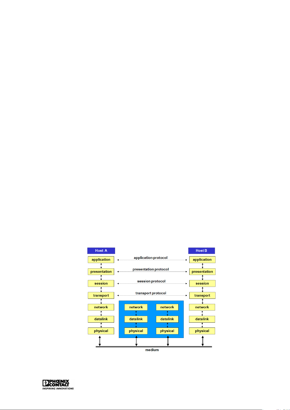
Figure 1.1: The OSI model Introduction 2
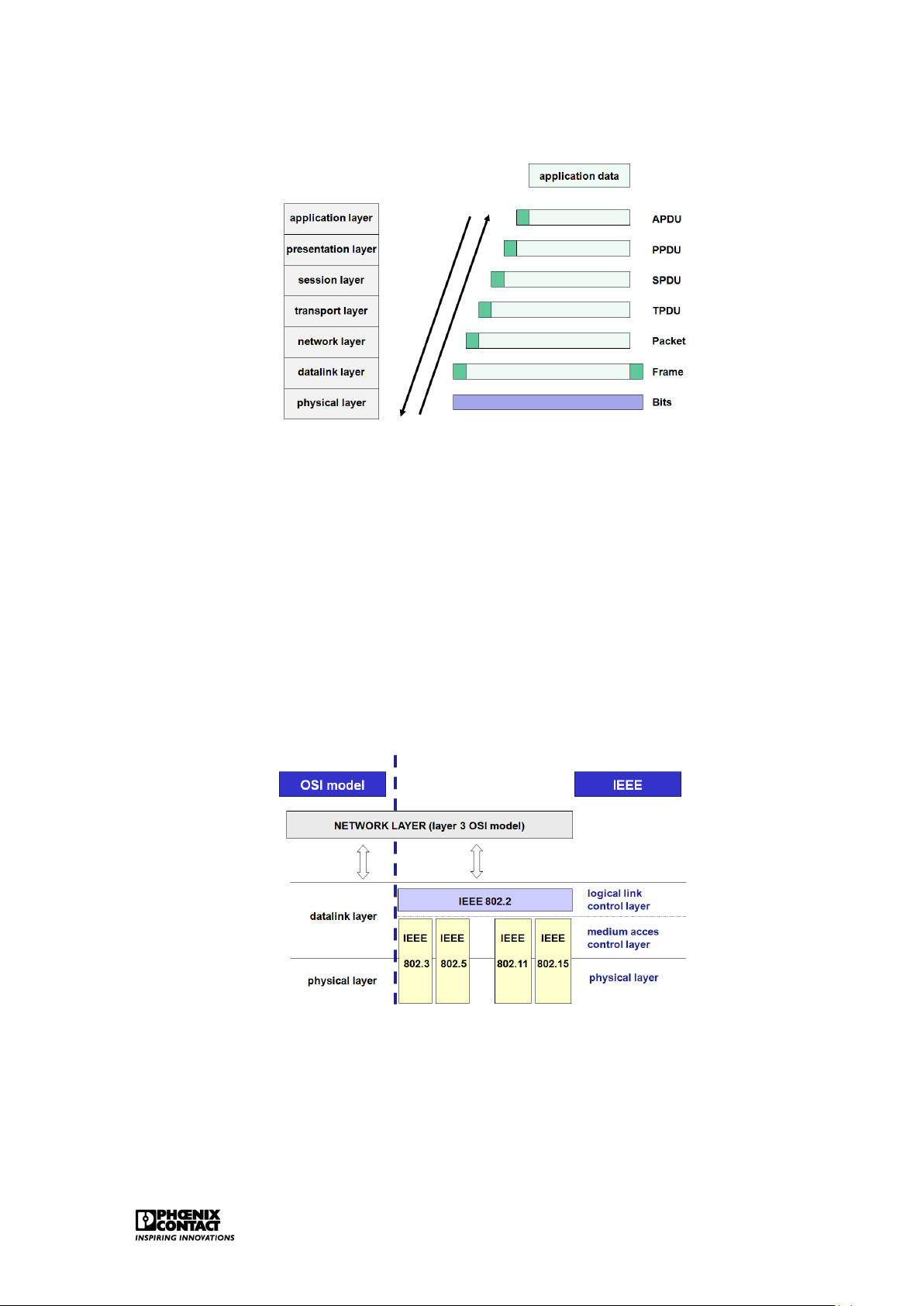
The OSI model consists of seven functional layers. Every layer contains a number of defined
functions. A limited enumeration of the different layers is given below: PHYSICAL LAYER (layer 1)
This layer ensures the connection with the medium via which the information is sent between
two points in the network: this means that this layer provides the mechanical, electrical or
optical entities that are required to realise, maintain and break off the physical connection. DATA LINK LAYER (layer 2)
The protocols of layer 2 specify how the frames eventually have to be sent over the network.
Layer 2 maintains an error detection- and correction mechanism in order to be sure that
transmission errors are handled and that data are correctly received on the other side. NETWERK LAYER (layer 3)
The addressing is configured on this level. This means that the network finds a route and
avoids congestion within the network. The network layer ensures the transport of messages
from one node to the other on the sender’s route to the final receiver. TRANSPORT LAYER(layer 4)
The transport layer is responsible for a reliable transmission of data. The transport layer
ensures a logical connection between both end systems of the network (a logical point to
point connection). This means that a faultless data transport can be realised whereby the
data is received in correct order by the receiver. SESSION LAYER (layer 5)
The control structure of the dialogue (session) between two applications over the network is
provided for here, as well as the setting up and termination of such a session.
PRESENTATION LAYER (layer 6)
The protocols in layer 6 determine how data is represented: this is necessary as different
computer systems represent numbers and characters in different ways. So, this layer en-
sures, amongst others, the conversion of character codes, e.g. from ASCII to EBCDIC. APPLICATION LAYER (layer 7)
This layer provides service to applications that run for the benefit of network system users.
It has been agreed for the reference model that the message to be sent by the sender will run
through these seven layers. Every layer of the model gives the message a header, starting
from layer 7 and then descending until layer 1, see figure ??. The header shows which data
communication functions have to be carried out.
For the functioning of the communication protocols, every layer exchanges information with
the corresponding layer on the other side of the connection, apart from the application data
that the final users of the connection send to each other. In the OSI model, every layer adds a
piece of information (header) to the user data on the sending side. The corresponding layer
on the receiving side removes this information again. The data link layer not only places
additional information in front of the transmitted data but often also behind it. This trailer
contains a check code for the detection of possible transport errors. Only the physical layer does not add anything. Introduction 3
Figure 1.2: Protocol overhead in the OSI model 1.2 LAN
A local network (Local Area Network (LAN)) has been developed to ensure communication
between computers, work stations and peripherals in an area of a very limited geographical size.
The connected stations in a LAN are autonomous, meaning that primary and secondary sta-
tions do not exist. Every station can set up, maintain and break off a connection with another
station. With regard to public networks, the four bottom layers of the OSI model require a
slightly different approach for a LAN.
The 802 committee of the Institute for Electrical and Electronic Engineers has established a number of standards for LANs.
Figure 1.3: Location LAN within the OSI model
Figure ?? shows the filling in of layers 1 and 2 in the OSI model by the IEEE802 standard.
Standard IEEE802.1 can be consulted for general concept on LANs.
Currently, the following work groups are active within the IEEE802 committee:
• IEEE802.1 Bridging (networking) and Network Management Introduction 4
• IEEE802.2 Logical Link Control • IEEE802.3 CSMA CD (Ethernet) • IEEE802.5 Token Ring
• IEEE802.11 Wireless LAN & Mesh (Wi-Fi certification) • IEEE802.15 Wireless PAN
– IEEE802.15.1 (Bluetooth certification)
– IEEE802.15.4 (ZigBee certification)
• IEEE802.16 Broadband Wireless Access (WiMAX certification)
• IEEE802.16e (Mobile) Broadband Wireless Access
• IEEE802.16.1 Local Multipoint Distribution Service
• IEEE802.17 Resilient packet ring
• IEEE802.18 Radio Regulatory TAG • IEEE802.19 Coexistence TAG
• IEEE802.20 Mobile Broadband Wireless Access
• IEEE802.21 Media Independent Handoff
• IEEE802.22 Wireless Regional Area Network Chapter 2 Ethernet 2.1 Introduction
Ethernet is the basis of LAN networks. The current LAN market is characterised by an, up to
now, unknown degree of standardisation on Ethernet. Due to its huge market share, Ethernet,
despite some disadvantages, scores over all alternative technologies. A short historical overview:
• 1980: Digital Equipment Corporation, Intel and Xerox released the first Ethernet spec-
ification, version 1.0, under the name Ethernet Blue Book or DIX standard. It defines
Thick Ethernet in case of 10Mbps CSMA/CD. The first Ethernet controllers, based on the
DIX standard, were available starting from 1982. The second and final version of the
DIX standard, version 2.0, was released in November 1982: Ethernet II.
• 1983: The Institute of Electrical and Electronic Engineers (IEEE) launches the first IEEE
standard for Ethernet technology. It was developed by the 802.3 group of the IEEE802
committee and this under the name IEEE802.3 Carrier Sense Multiple Access with Col-
lision Detection Access Method and Physical Layer Specifications. IEEE reworked some
parts of the DIX standard, especially with regard to the definition of the frame determi- nation.
• 1985: IEEE802.3a; definition of thin Ethernet, cheapernet or 10Base2
• 1987: IEEE802.3d; Fiber Optic Inter Repeater Link (FOIRL). Use of two fibre optic cables
to extend the distance between 10 Mbps repeaters up to 1000m.
• 1987: IEEE802.3e; 1Mbps over twisted pair
• 1990: IEEE802.3i; release of the popular 10Base-T; 10Mbps over UTP category 3
• 1993: IEEE802.3j; 10Base-F: distances greater than 2 km over fibre optic
• 1995: IEEE802.3u; 100Base-T and 100Base-F
• 1997: IEEE802.3x: full-duplex Ethernet
• 1997: IEEE802.3y; 100Base-T2
• 1998: IEEE802.3z; 1000Base-X standard; generally known by the name Gigabit Ether- net Ethernet 6
• 1999: IEEE802.3ab; Gigabit Ethernet over twisted pair
• 1999: IEEE802.3ac; 802.1Q: definition of the Q tag with VLAN and priority information.
• 2003: IEEE802.3af; Power over Ethernet
• 2006: IEEE802.3an; 10GBase-T
• 2006: IEEE802.3aq; 10GBase-LRM, Ethernet over multimode fiber
Ethernet is only a specification of layers 1 and 2 in the OSI model. It is not a complete network
protocol but a subnet on which other protocols such as the TCP/IP suite can work.
The most important functions of ETHERNET are:
• Filling in of the physical layer
– sending and receiving the serial bit streams over the medium.
– detecting collisions.
• Filling in of the data link layer – MAC sublayer:
∗ access mechanism to the network (CSMA/CD).
∗ building of the data frames. – LLC sublayer: ∗ data reliability.
∗ supply data channels for higher-level applications. 2.2
The physical implementations
The most important implementations over the years are: • Thick Ethernet (10Base5) • Thick Ethernet (10Base2)
• Broadband Ethernet (10Broad36)
• Ethernet over twisted pair (10Base-T)
• Ethernet over Fiber (10Base-F)
• Fast Ethernet (100Base-T / 100Base-F)
• Gigabit Ethernet (1000Base-T) • Wireless Ethernet Ethernet 7 2.2.1
Implementations based on coax
The original Ethernet was designed around the concept of a bus topology. The first imple-
mentations of Ethernet were based on a thick yellow coax cable - thick Ethernet - also named 10Base5.
Features of the original Ethernet: • 10Mbps
• Baseband (basic band transmission) • max. 5 x 100 = 500 meter
• max. 100 transceivers per segment
Thick Ethernet coax cables have a marking every 2.5 metres in order to ensure correct po-
sitioning of the 10Base5 transceivers (or MAUs). These transceivers are used to connect
stations to the network. The transceivers can be positioned every 2.5 metres, this avoids
reflections of the signals, resulting in a poor transmission quality.
This type of implementation has been superseded. The thick, rigid yellow coax was rapidly re-
placed by the black, more flexible coax which resulted in the implementation of thin Ethernet
(10Base2). The connection of the different stations is realised by T-shaped BNC connectors
whereby a maximum segment length of about 200 metres can be applied.
Important cabling detail that is required for most bus technologies: the terminating resis-
tance (terminator) - a small, cheap device that has to be mounted on all endings of the coax
cables that form an Ethernet. A terminating resistance consists of a resistance that connects
the central core of the cable with the shielding: when an electrical signal reaches the termi-
nating resistance, this is discarded. For the correct functioning of a network, the terminating
resistance is indispensable as the end of the non-terminated cable reflects electrical signals
just as a mirror reflects light. When a station tries to send a signal over a non-terminated
cable, then this signal will be reflected by the cable end. When the reflection reaches the
sending station, interference will occur. 2.2.2
Implementations based on twisted pair
The major problem with coax is that only half duplex communication can be applied. The
applied bus structure is also not ideal if certain problems occur. In order to break through
the bus topology, Ethernet has switched to a topology where twisted pair can also be used:
all stations are connected with one or more central hubs. This way, a star topology can be
worked out. The network can easily be extended and checked in this way and it facilitates er-
ror detection. The maximum segment length between a participant and a hub is 100 metres.
The variants on the basis of twisted pair have evolved from 10Base-T (10Mbps) to 100Base-T
(100Mbps) to 1000Base-T (1000Mbps). Ethernet 8
Figure 2.1: The MAU for 10/100Base-T
The MAU, developed for twisted pair, is equipped with 4 data pins: 2 for sending, 2 for receiv-
ing. This is the basis for full duplex Ethernet. In principle, any point to point communication
is possible. Therefore, every host has to be connected directly with a structure element: a hub or a switch. Fast Ethernet
The UTP cable, e.g. CAT5 (Class 5) UTP (Unshielded Twisted Pair), supports speeds up to
100Mbps. The cable consists of 8 wires, arranged in 4 pairs. The 4 pairs can be identified as
1 is always completely coloured and the other one has the same colour with white parts in
between. Only 2 of the 4 pairs are used in 10/100Base-T (pair 2: orange/white and orange
and pair 3: green/white and green).
The IEEE specification for Ethernet 10/100Base-T requires that the one used pair is connected
to pin 1 and pin 2 of the connector while the second pair is connected to pin 3 and pin 6. The
other two unused pairs will be connected to pin 4 and 5 and on pin 7 and 8.
Table 2.1: Pin configuration for Fast Ethernet Pin Colour Function 1 green with white +TD 2 green -TD 3 orange with white +RD 4 blue unused 5 blue with white unused 6 orange -RD 7 brown with white unused 8 brown unused
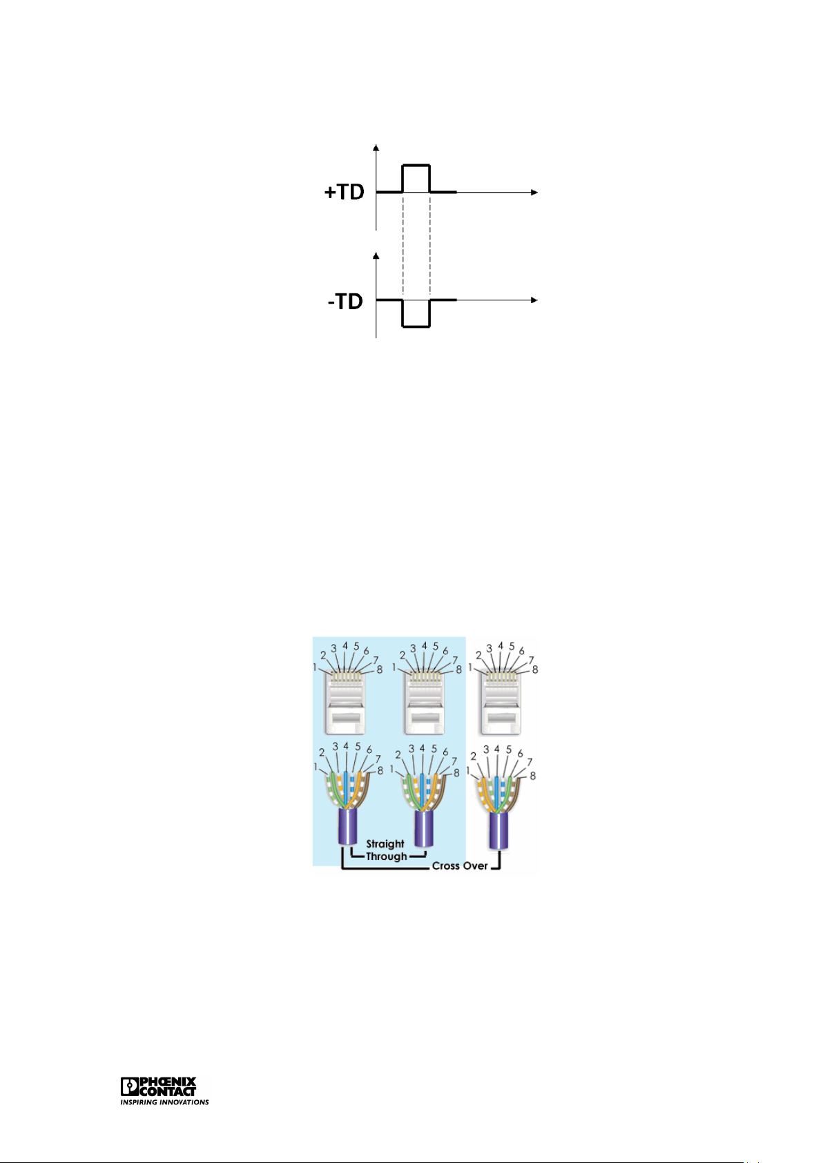
Table 2.1 shows the pin configuration for 10/100Base-T. TD stands for Transmitted Data, RD
stands for Received Data. The plus- and the minus signs indicate that the signal is sent
mirrored via two data lines, also see figure 2.2. Ethernet 9
Figure 2.2: Transmission technology for 10/100Base-T
The straight-through cable, also called patch cable, is the cable that we get when we connect
both sides of the cable pair 2 with pin 1 and pin 2, while pair 3 is connected with pin 3 and pin
6. This cable can be used for connections between the patch panel and the hub/switch, the
PC and the hub/switch or the PC and the wall. This cable is generally used for the connection
of a structure element and an end element.
A cross-over cable is required to set up the PC-PC connections (connection of two end ele-
ments) and to secure connections between hub/switch and another hub/switch (connection
between two structure elements). In order to make a cross-over cable, we have to switch the
used pairs. Along one side, pair 2 has to be connected with pin 3 and pin 6 while pair 3 has
to be connected with pin 1 and pin 2.
Figure 2.3: Twisted pair cabling, 10/100Base-T
Current Ethernet ports support autocrossing. This means that it can be detected automati-
cally which cable is used and the crossing will be corrected internally if necessary.
The IEEE Fast Ethernet has defined 100Base-T as extension on the 10Base-T.
Fast Ethernet is characterised by: Ethernet 10
• Data transmission at a speed of 100Mbps • Full Duplex communication • Wireless Ethernet
In Fast Ethernet, a mechanism is provided for auto negotiation: this makes it possible to built
Ethernet interfaces that switch automatically between 10Mbps and 100Mbps.
For the 10Base-T standard, every data bit is coded in one physical bit. In other words, for
a group of eight data bits, eight signals are generated in the cable. The 10Mbps data rate
means a clock rate of 10MHz. For every clock pulse, one single bit is sent.
100Base-T uses the so-called 4B/5B scheme whereby each group of four bits is coded in a 5
bit signal. So, one single bit is not exactly converted into one single signal in the cable. Data stream: 0111010000100000 4 bit pattern: 0111 0100 0010 0000 5 bit code: 01111 01010 10100 11110
The applied clock rate is 125MHz (5/4 x 100). Cat5 cables are certified for a transmission speed up to 125 MHz. Gigabit Ethernet
Gigabit Ethernet targets a data rate of 1000Mbps. If the CAT5 Ethernet cables have to be
used for this, for example, then this causes a problem as they only support a clock rate up to
125MHz. In order to realise this, the technology has to be adapted.
First, 1000Base-T codes two bits per clock signal (00, 01, 10 and 11) and uses four voltage levels for this.
Furthermore, 1000Base-T uses all four data pairs of an Ethernet cable. The four data pairs
are applied here bi-directionally. Data are sent or received via all four data pairs.
Gigabit Ethernet therefore still uses the 100Base-T/Cat5 clock rate of 125MHz. A data rate
of 1000Mbps is reached as 2 bits are being processed for every clock pulse and this is done
via four data pairs. This modulation technology is called 4D-PAM5 and currently uses five
different voltage levels. The fifth voltage level is used for the error mechanism. Table2.2
shows the Gigabit Ethernet pin configuration. BI stands for bi-directional while DA, DB, DC
and DD stands for data A, data B, data C and data D. Ethernet 11
Table 2.2: Pin configuration for Gigabit Ethernet Pin Colour Function 1 green with white +BI_DA 2 green -BI_DA 3 orange with white +BI_DB 4 blue -BI_DB 5 blue with white +BI_DC 6 orange -BI_DC 7 brown with white +BI_DD 8 brown -BI_DD 2.2.3
Implementations based on fibre
In order to make longer segment distances possible, the glass fibre cable was integrated
as a suitable interface. The first fibre glass variants are known by the name 10Base-F and
100Base-F. Separate fibres are used all the time for the sending and receiving of data.
Gigabit Ethernet over fibre has been developed for the full-duplex mode with a data rate of
1000Mbps. There are two different variants for Gigabit Ethernet. 1000Base-SX and 1000Base- LX.
1000Base-SX uses light pulses with short wavelength over multimode fibre. 1000Base-LX
uses light pulses with long wavelength over multimode or single-mode fibre.
Recently, 10Gigabit Ethernet over fibre with different variants also has been added. 2.2.4 Wireless LAN IEEE802.11
The IEEE defines different standards for wireless LAN in their IEEE802.11 description. The
radio connections for a Wireless LAN take place in the 2.4 GHz frequency band, the so-called
ISM band (Industrial, Scientific and Medical) or in the 5 GHz band. No licences are required
for this. A Wireless LAN uses the so-called spread spectrum technology. This technology
is specifically meant for fault-prone transmission channels. This is important as these fre-
quency bands (especially the 2.4 Ghz) are also used by many other devices, e.g. Bluetooth.
A wireless network is in general much less fast than a fixed wired network. A major advantage is the flexibility.
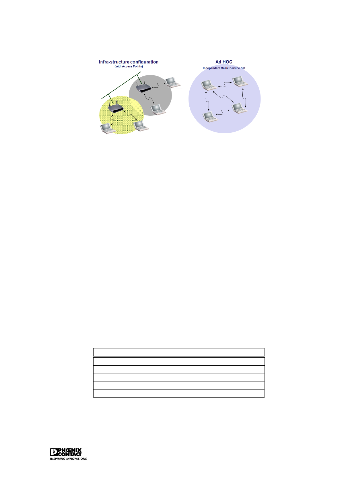
With regard to physical implementation, the IEEE802.11 provides the infrastructure configu-
ration or the Ad Hoc configuration. Ethernet 12
Figure 2.4: Physical implementation of WLAN
Infrastructure configuration is the configuration whereby a wireless access point is used to
connect a wireless LAN with a cabled LAN. The wireless access point functions as central
point for the routing of the all wireless data traffic. Wireless-enabled computers that are
included in an infrastructure mode form a group that is called a Basic Service Set (BSS). At
a certain moment, a maximum of 64 individual computers can be included in a BSS. This
is because the capacity of the wireless access point is limited to 64 clients. The complete
wireless network has a unique SSID (Service Set Identifier) and is also has a network name.
This name only applies to the wireless network.
Ad hoc or peer-to-peer relates to a wireless configuration in which every participant commu-
nicates directly with the other. An actual organisation of the network is therefore not possible
here. An ad hoc wireless LAN consists of a group of apparatuses each equipped with a wire-
less adaptor that is directly connected to each other and form an independent wireless LAN in this way. WLAN standards
Different standards are defined within the IEEE802.11. These standards use different mod-
ulation technologies in order to obtain improved transmission speeds. Table 2.3 displays an
overview of the different standards.
Table 2.3: WLAN standards within the IEEE802.11 Standard Frequency band Data transmission IEEE802.11b 2.4GHz 11Mbps IEEE802.11g 2.4GHz 54Mbps IEEE802.11a 5GHz 54Mbps IEEE802.11h 5GHz 54Mbps IEEE802.11n 5GHz and/or 2.4GHz 600Mbps Ethernet 13 IEEE802.11b/g
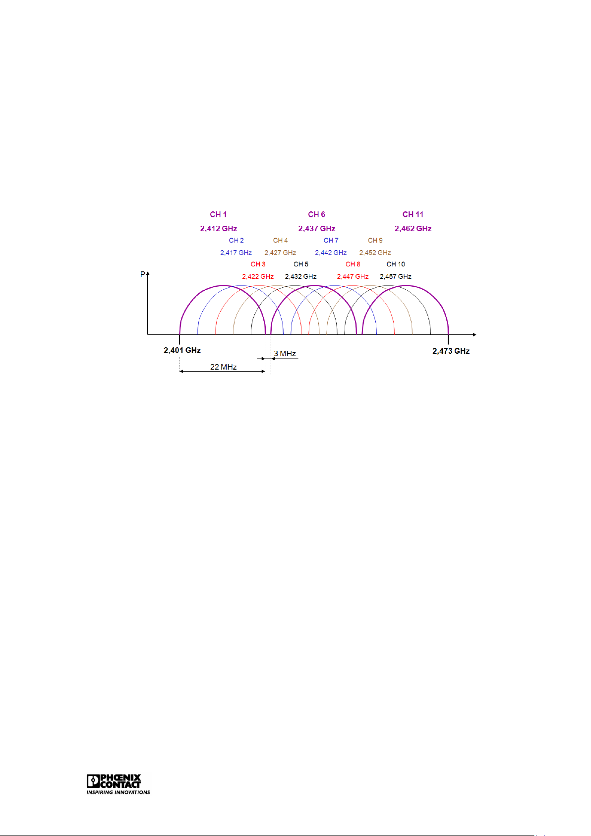
IEEE802.11b/g uses the 72 MHz band part of the 2.4 GHz band. 11 channels of 22MHz band
are defined here, in accordance with the FCC rules. Theoretically this would mean that the
bandwidth for these 11 channels is 242 Mbps (11x22 Mbps). In reality, this has to be reviewed
as these channels overlap for a large part. Figure 2.5 shows that there are only three non-
overlapping channels: channel 1, channel 6 and channel 11.
Figure 2.5: The 2.4GHz band for WLAN
The ETSI defines a slightly wider frequency band for Europe, including 13 channels of 22 MHz
band. This means, in principle, that we can use 4 barely overlapping channels in Europe.
These are channel 1,5,9 and 13.
The IEEE802.11b supports a maximum speed up to 11 Mbps. The IEEE802.11g supports
a maximum speed up to 54 Mbps. The speed is decreased dynamically in case of a bad
connection or great distance to the access point. IEEE802.11a/h
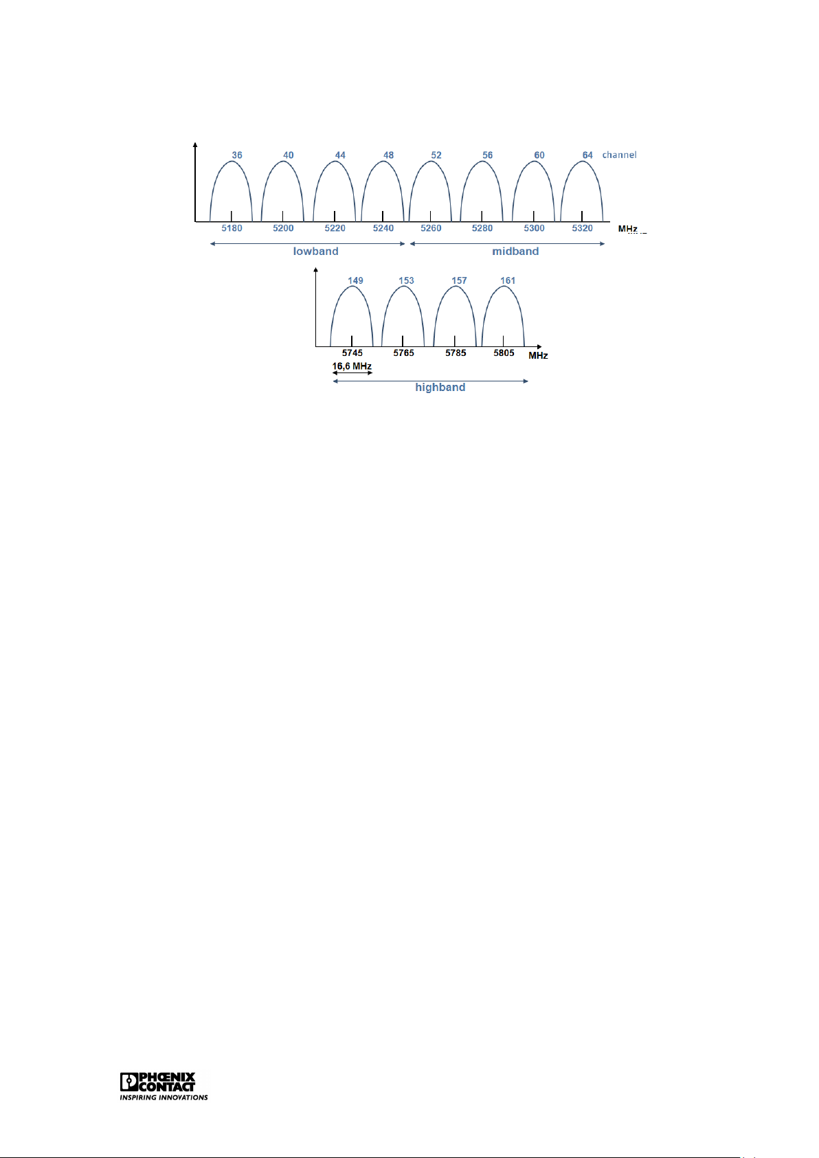
IEEE802.11a uses the complete 5GHz band. With the application of OFDM (Orthogonal Fre-
quency Division Multiplexing), the maximum (theoretical) speeds of up to 54Mbps are reached
with IEEE802.11a. Figure 2.6 shows the different channels within the 5GHz band. Within Eu-
rope, this means that 8 non-overlapping channels of 20MHz wide can be used over the two
lowest bands of the 5GHZ UNII band. Ethernet 14
Figure 2.6: The 5GHz band for WLAN
As opposed to the USA, the use of the 5GHz band in Europe has quite a few restrictions.
Therefore, the IEEE802.11a is converted into the IEEE802.11h. Two important protocols were
added in order to eventually comply with the European regulations:
• DCS (Dynamic Channel Selection):the AP will automatically look for another channel if
it appears that the channel is used by another application.
• TPC (Transmit Power Control): just the required capacity is transmitted, if two partici-
pants are in close vicinity, then the AP will adapt the capacity to the required level. IEEE802.11n
This recent standard uses MIMO (multiple input - multiple output), a technique to transmit
data wirelessly by means of several reception- and send antennas whereby a transmission
speed of maximum 600Mbps is obtained if 4 channels of 40MHz each are used. 2.2.5 Bluetooth
The basic technology (two bottom layers of the OSI model) is standardised in the IEEE802.15.1.
Moreover, the Bluetooth SIG (Special Interest Group) defines different application profiles,
e.g. serial communication and transmission of Ethernet data frames.
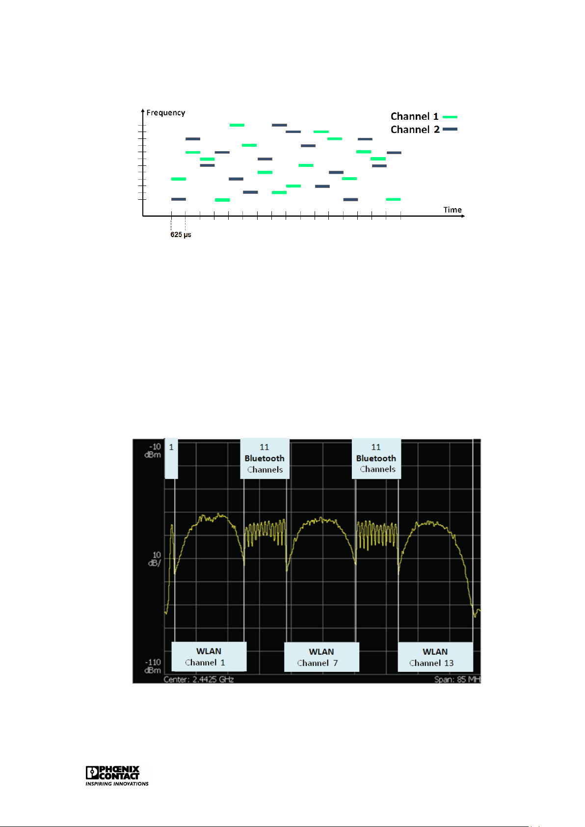
Bluetooth uses the 2.4 GHz licence-free ISM band. As opposed to WLAN, the data to be
sent are not spread out over a wider frequency band but FHSS (Frequency Hopping Spread
Spectrum) is applied. The 2.4 GHz band is divided over 79 channels of 1 MHz. Figure 2.7
shows the functioning of FHSS. 1600 hops per second can be carried out. Each time, every
data frame is sent on another frequency. This means that different logic channels can be active in parallel. Ethernet 15
Figure 2.7: FHHS technology
A great advantage of the use of Bluetooth in the industry is the perfect co-existence with
WLAN. If there is interference on a Bluetooth frequency as a WLAN channel is active on the
same frequency, then Bluetooth can avoid this/these frequency (ies). As this is a frequently
occurring issue, Bluetooth has integrated an automated co-existence mechanism: Adaptive Frequency Hopping (AFH).
This mechanism enables Bluetooth to suspend certain ’bad’ frequencies temporarily from the
hopping list. Figure 2.8 shows how there is enough space in case of a full 2.4GHz band where
three separate WLAN channels are active. The WLAN channel uses a statistic frequency band.
Bluetooth can adapt and choose from adequate number of frequencies to avoid interference.
Figure 2.8: Co-existence of Bluetooth and WLAN