Homework 3 MPS 2020
Tài liệu học tập môn Electrical Engineering tại Trường Đại học Quốc tế, Đại học Quốc gia Thành phố Hồ Chí Minh. Tài liệu gồm 2 trang giúp bạn ôn tập hiệu quả và đạt điểm cao! Mời bạn đọc đón xem!
Môn: Electrical Engineering 8 tài liệu
Trường: Trường Đại học Quốc tế, Đại học Quốc gia Thành phố Hồ Chí Minh 2 K tài liệu
Tác giả:
Preview text:
HCMIU Instructor: Hồ Trung Mỹ
Micro-processing systems–AY1920-S2 Homework #3 Due Friday, Jun 5
Note: We use the AVR ATmega32 microprocessor and the WinAVR in this quiz.
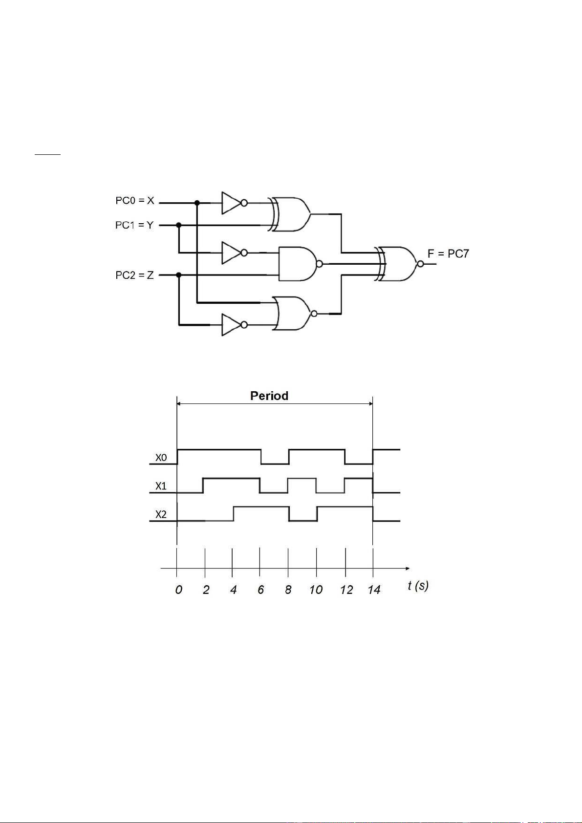
Q1. (30 pts) Implementation of the following combinational logic circuit using an AVR ATmega32. Write your C code.
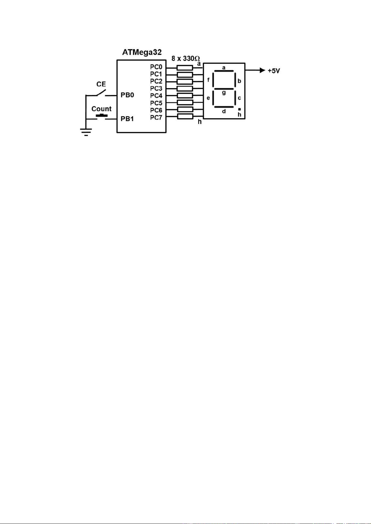
Q2. (30 pts) Design of a digital waveform generator using ATMega32 with the timing diagram in the following
figure with notations: X0 = PC0, X1=PC1, and X2=PC2. We use Port C of ATMega32 for this design. Write
your C code. (Hint: Use delay functions for timing and assume that XTAL = 1 MHz)
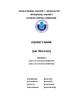
Q3. (40 pts) Given a principle schematic diagram of a 1-digit BCD up counter as follows: (Intitial Count value = 0)
· PB0 = 0 (CE = Counter Enable) Þ Counter unchanges.
· PB0 = 1Þ Counter counts up when there is a negative edge signal on Count (PB1) o
With the count sequence: 0, 1, 2, 3, 4, 5, 6, 7, 8, 9, 0, 1, . . .
The 7-segment LED displays the current counter value. Write your C code.
(Note: 7-segment LED is CA type, it means that for example, PC0 = 0 Þ LED on segment a is ON.)
Tài liệu liên quan:
-
Lab Report Template Môn Electrical Engineering | Trường Đại học Quốc tế, Đại học Quốc gia Thành phố Hồ Chí Minh
122 61 -
Lab 2 Kirchoff’s Current And Voltage Laws | Môn Electrical Engineering - Trường Đại học Quốc tế, Đại học Quốc gia Thành phố Hồ Chí Minh
98 49 -
Lab 7: FET Amplifier Study Guide | Môn Electrical Engineering - Trường Đại học Quốc tế, Đại học Quốc gia Thành phố Hồ Chí Minh
98 49 -
Review Midterm: Differential & Integration Amplifiers Concepts | Môn Electrical Engineering - Trường Đại học Quốc tế, Đại học Quốc gia Thành phố Hồ Chí Minh
107 54 -

Instruction Set Overview: Key Registers and Addressing Modes | Môn Electrical Engineering - Trường Đại học Quốc tế, Đại học Quốc gia Thành phố Hồ Chí Minh
96 48