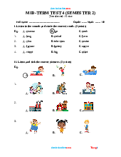
iêu đề chi tiết rõ ràng (30 ký tự) sẽ được duyệt nhanh hơn Bao gồm Trườnglớp môn học chươngb
abc
Môn: Quản trị tài chính doanh nghiệp 283 tài liệu
Trường: Trường Đại học Kinh Tế Quốc Dân 8.6 K tài liệu
Tác giả:


Preview text:
Academic Journal of Engineering and Technology Science
ISSN 2616-5767 Vol.7, Issue 4: 25-35, DOI: 10.25236/AJETS.2024.070405
Design and walking planning of bionic quadruped robot
Fengning Yang1,a,#, Hang Zhang2,b,#
1Department of Automation, Century College, Beijing University of Posts and Telecommunication, Beijing, China
2School of Mechanical and Electrical Engineering, Huangshan University, Huangshan, Anhui, China
ayang_fengning@163.com, b3132477897@qq.com #Co-first author
Abstract: We present the structure of this biomimetic quadruped robot and analyze its leg structure.
We conducted a joint simulation using SolidWorks and ADAMS to validate the design's rationality. We
constructed a physical prototype of the biomimetic quadruped robot for gait testing. Motion control is
a critical aspect of quadruped robot design, and motion analysis provides the foundation for designing
a physically robust and stable prototype, as well as for gait planning. After analyzing the essential
poses required for motion, we designed the mechanical structure of the biomimetic quadruped robot.
Employing ADAMS, we established a simulation model that takes into account the foot's contact with
the ground, enabling gait planning and elucidating the dynamic behavior of the quadruped robot.
Keywords: Bionic; Quadruped robot; Structural design; Gait Planning 1. Introduction
Four robot research can be traced back to the fourth century, the early foot robot its control system
is composed of logic circuit, under the control of the operator robot can move and some specific action,
later with the development of computer technology, scientists developed by the computer control foot
robot, by some sensor feedback to control the movement of the robot leg[1]. Since ancient times, we
have never stopped exploring the field of robotics[2]. One of the world's true quadrupedal walking
robots was built by Frank and McGhee 20 in the middle century, and there has been foreign research on
hydraulic driven foot robots. The United States was one of the first countries to start the study[3]. In
1984, McGhee designed OSU Hexapod, the first foot robot controlled by electronic computer; in 1992,
Boston Dynamics designed a large quadruped robot and humanoid robot; in 1999, Sony released the
world's first foot robot product Aibo electronic dog; in 2008, Boston Dynamics released the latest robot
"Big Dog"; In 2018, Boston Dynamics began mass production of the Spot Mini robot.
Siped robot has important value in the world, mainly reflected in the following aspects: 1. It
promotes scientific and technological innovation: quadruped robot is one of the important research
directions in the field of robot. Its development has promoted the innovation and progress of robot
technology, and promoted the development of artificial intelligence, motion control and other fields[4].
2. Promoted the industrial development: The development of the quadruped robot has promoted the
development of the robot industry, involving the development of machinery manufacturing, electronic
technology, software development and other fields.3. Promoted international cooperation: the research
and development of quadruped robots requires international cooperation and exchanges, and the
cooperation among countries in this field helps to jointly promote technological development and
promote world peace and development. In general, the development of four-legged robots not only
promotes scientific and technological innovation and industrial development, but also helps to solve the
challenges faced by human beings and improve the quality of life.
The military development of quadruped robots is of great significance, which is mainly reflected in
the following aspects: 1. Reducing the burden of soldiers: quadruped robots can carry equipment,
materials and weapons[5], Provide support and help to soldiers, reduce the burden of soldiers, and
improve their combat ability and survivability[6]. 2. Reconnaissance and attack: quadruped robots can
carry a variety of sensors and weapons to perform reconnaissance and attack tasks, which can perform
tasks in complex environments and improve the combat effect.3. Improve combat efficiency:
quadruped robots can carry out various military tasks, such as reconnaissance, patrol, search and rescue,
Published by Francis Academic Press, UK -25-
Academic Journal of Engineering and Technology Science
ISSN 2616-5767 Vol.7, Issue 4: 25-35, DOI: 10.25236/AJETS.2024.070405
etc., which can replace soldiers to perform dangerous tasks, thus reducing the risk of casualties of
soldiers and improving combat efficiency[7]In general, the quadruped robot can improve the combat
efficiency and combat effectiveness of the army and enhance the national defense capability. Therefore,
military departments and research institutions in various countries are actively studying and applying
quadruped robot technology to enhance their military strength and security orientation capabilities[8].
Nowadays, quadruped robots are developing rapidly in various countries[9].At present, the United
States is leading in the field of quadruped robots, which has many excellent research institutions and
enterprises, such as Boston Dynamics, they have developed a series of advanced quadruped robots,
such as BigDog, Spot, etc[10]. Japan is also an important research country in the field of quadruped
robots, with many research institutions and enterprises committed to the research and development of
quadruped robots, such as AIBO of SONY, QUINCE of Kyoto University and so on. Germany has a
strong strength in the field of robotics technology, and has also made certain achievements in the field
of quadruped robotics, such as Festo's BionicOpter, Laufmaschine of DFKI, and so on. The Korea
Institute of Industrial Technology developed the KITECH p-2 in 2010 and the Jin Poong in 2014,
which is capable of advancing, reversing and falling down[11]. China has done some research and
development in the field of robotics technology[12], Such as the Institute of Robotics of the Chinese
Academy of Sciences, the research team of Tsinghua University, and Shandong University. Shandong
University was one of the first institutions to study quadruped robots[13]. In 2010, Scalf-I, a quadruped
robot, was developed by Shandong University. The hydraulic oil source is not integrated in the robot
body, and the indoor fixed hydraulic pump station is used to supply the energy. Under laboratory
conditions, Scalf-I was able to walk at 1.2 m/s at 80kg weight.
Quadruped robots have many advantages. For example, quadruped robots can adapt to different task
requirements through different gait, such as fast running, slow walking or crawling, and can move in
different terrain and environments[14]; The legs of four-legged robots simulate the way animals walk,
and they can walk on a variety of terrain, such as rugged, slippery, or uneven ground, an ability that is
particularly important in natural disaster relief and field exploration[15]; Some quadruped robots have
powerful artificial intelligence technology that can realize autonomous learning and decision-making[16].
And compared with the bipedal robot quadrupedal robot has stronger stability and load capability[17].
At the same time, the current quadruped robot also has many disadvantages, the quadruped robot
needs to carry a large number of batteries or other energy supply devices, but the current battery life is
limited, resulting in the short working time, while walking or running, affect the working efficiency
and reliability of the robot, the robot development and manufacturing costs, and its promotion and
popularization in the commercial application field is limited; the quadruped robot can not help people
more effectively in life. For power and life ability, movement stability and quadruped robot brings
convenience to our daily life these shortcomings, we designed a new type of quadruped robot with
robotic arm, he has the original no robotic arm of quadruped robot function, and because of the two
mechanical arm, he has more can help people in their daily life[18].
Section1 In view of the lack of power and endurance of the original quadruped robot, we can
improve the endurance of the quadruped robot and extend the working time by developing high energy
density batteries or other new energy supply devices. This year, the new energy vehicle industry is
developing rapidly, and the battery of new energy vehicles can be modified for four-legged robots.
Section3. For the problem of insufficient quadrupedal robot movement stability, we improve the
robot control algorithm, the leg structure, sensor system and kinematics design, improve the stability of
the robot, and can move the original foot robot foot movement with the combination of wheel
technology, which not only can improve the robot movement speed, can also reduce the instability and
fall[19]. The robot leg mechanism can also be changed to a 3 degrees of freedom parallel leg mechanism
of 2R1T[20], Or a new string and mixed leg mechanism
Section4. In view of the lack of practicality of the quadruped robot in our life, we installed two
robotic arms on both sides of the body of the original quadruped robot. Through the combination of
algorithm and sensor, the two robotic arms can achieve simple grasping and door opening action.
2. Scheme design of Bionic quadruped robot
2.1. The concept and classification of biomimetic robots
A robot is an intelligent machine capable of semi-autonomous or fully autonomous operation.
Published by Francis Academic Press, UK -26-
Academic Journal of Engineering and Technology Science
ISSN 2616-5767 Vol.7, Issue 4: 25-35, DOI: 10.25236/AJETS.2024.070405
Through programming and automatic control, robots can perform tasks such as work or movement.
They possess basic features such as perception, decision-making, and execution, and can assist or even
replace humans in carrying out dangerous, heavy, or complex tasks. This enhances work efficiency and
quality while also serving human life by expanding or extending the range of human activities and
capabilities. Robots are classified based on their mode of locomotion into categories such as wheeled
mobile robots, bipedal robots (single-legged, double-legged, and multi-legged), tracked mobile robots,
crawling robots, slithering robots, and swimming robots.
2.2. Design and analysis of bionic quadruped robot
From a bionic perspective, traditional quadruped robot leg configurations can be broadly
categorized into two types: mammalian and reptilian structures. Large-sized quadruped robots typically
adopt the structure of mammals, consisting of four legs and a trunk with the design focused on the
interaction between the legs and trunk. The trunk in traditional quadruped robots is rigid, designed
primarily around its legs. Quadruped robot legs require at least 3 degrees of freedom to achieve free
swinging in space, thus their leg mechanisms mainly utilize 3R serial linkages.
Mammalian-style quadruped robots are generally larger in size and suitable for medium to
large-scale applications. They possess a significant vertical leg workspace enabling them to overcome
higher obstacles and exhibit fast running speeds through jumping motions. However, due to their high
center of gravity, they have poorer stability requiring complex sensing and control systems to maintain stable locomotion.
On the other hand, reptilian-style quadruped robot structures are relatively simpler with hip joint
axes perpendicular to the plane of the body for leg swing motion while other joint axes are
perpendicular to the hip joint axis but parallel to the body plane for bending and extension movements.
These robots are typically smaller in size compared to mammalian-style ones and have limited vertical
leg workspace resulting in lower obstacle-crossing abilities and slower movement speeds. Nevertheless,
their lower center of gravity provides greater stability due to a larger support polygon formed by their feet.
Although both styles share similarities in leg mechanism form, they offer different configurations
corresponding to distinct bionic forms based on animal locomotion principles.
2.3. Leg structure analysis
The joint coordinate system can describe the motion of each independent joint in the biomimetic
quadruped robot. The joint coordinate system of the leg structure of the biomimetic quadruped robot
follows the right-hand rule, with the thumb, index finger, and middle finger of the right hand
representing the Z-axis, X-axis, and Y-axis of the joint coordinate system, respectively.
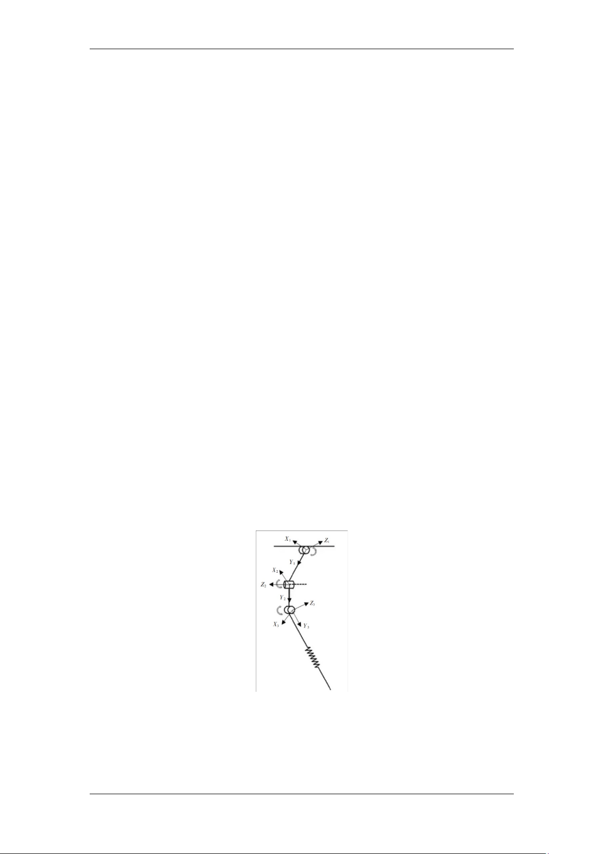
Figure 1: Leg joint coordinate system
The leg joint coordinate system is shown in Figure 1, where the Z-axis of each joint coordinate
system is the rotation axis of the corresponding joint. The Z1 axis direction and Z3 axis direction are
the same, and the Z2 axis direction is perpendicular to the Z1 axis direction and Z3 axis direction. The
Y-axis of the joint coordinate system falls on the link between the joints of the leg, and the direction
points down to the next joint and is perpendicular to the X-axis direction. By changing the angle of the
Published by Francis Academic Press, UK -27-
Academic Journal of Engineering and Technology Science
ISSN 2616-5767 Vol.7, Issue 4: 25-35, DOI: 10.25236/AJETS.2024.070405
No. 1 servo motor up and down, the waist joint of the biomimetic quadruped robot is controlled,
realizing the lifting and lowering of the legs of the biomimetic quadruped robot. By changing the angle
of the No. 2 servo motor left and right, the hip joint of the biomimetic quadruped robot is controlled,
completing the left and right movement of the biomimetic quadruped robot. By changing the angle of
the No. 3 servo motor up and down, the knee joint of the biomimetic quadruped robot is controlled,
realizing the kicking action of the foot of the biomimetic quadruped robot, so that the biomimetic
quadruped robot can realize walking on various complex terrains by changing the leg's movement
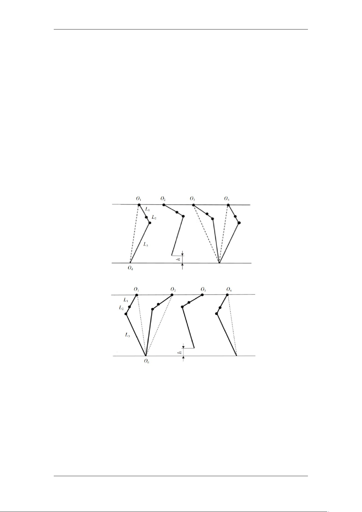
posture. The leg movements of the bionic quadruped robot in front and behind are shown in Figure 2
and 3, respectively. There are three linkages L1, L2, and L3 in the front and rear leg structures,
respectively, representing the thigh, hip, and calf. The black dots represent the waist joint, hip joint, and
knee joint. From Figure 4, it can be seen that by bending the knee joint of the front leg inward, the calf
is drawn inward, and the waist joint is bent outward to obtain the maximum height of the bionic
quadruped robot's foot off the ground h, and the corresponding stride length. Then the knee joint is bent
outward to determine the foot's landing position, and the waist joint and knee joint return to their initial
angles, completing a cycle of gait movement. From Figure 5, it can be seen that the gait movement of
the rear leg is opposite to that of the front leg. By bending the waist joint of the rear leg inward, the
corresponding stride length is obtained, the knee joint is bent inward to draw the calf inward, and the
maximum height of the bionic quadruped robot's foot off the ground h is obtained. Then the waist joint
and knee joint return to their initial angles to complete a cycle of gait movement. It can be concluded
from the analysis that the stride length of the bionic quadruped robot is determined by the waist joint,
and the maximum height of the foot off the ground is determined by the knee joint.
Figure 2: Gait movement of front legs of bionic quadruped robot
Figure 3: Gait movement of hind legs of bionic quadruped robot
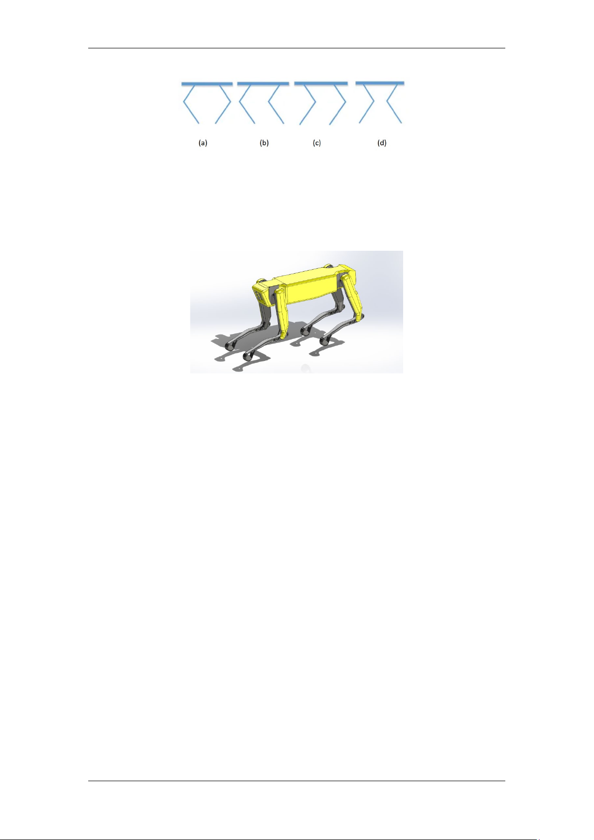
2.4. The configuration types of four legs of bionic quadruped robot
From Figure 4, the figure shows the four leg configurations of the quadruped robot, which from left
to right are: front knee and back elbow type, full elbow type, full knee type, front elbow and back knee type.
Published by Francis Academic Press, UK -28-
Academic Journal of Engineering and Technology Science
ISSN 2616-5767 Vol.7, Issue 4: 25-35, DOI: 10.25236/AJETS.2024.070405
Figure 4: Leg configuration type
In the context of leg freedom degree configuration, the most fundamental setup involves a
two-degree-of-freedom leg, comprising a hip joint swing degree of freedom and a knee joint degree of
freedom. This configuration is frequently employed in small-scale robotic canines to minimize costs. A
more prevalent arrangement is the three-degree-of-freedom leg, which incorporates an additional
abduction degree of freedom at the hip. Nevertheless, this supplementary range of motion is limited
and may not be substantial during typical quadrupedal locomotion.
Figure 5: Quadruped robot design drawing
3. Kinematic gait analysis and simulation
3.1. The significance of gait planning
The objective of gait planning is to achieve stable periodic motion for the bionic quadruped robot.
By planning the foot trajectory of the bionic quadruped robot, which adopts a single-leg
three-degree-of-freedom design, kinematic analysis of the single leg is conducted to solve for the
inverse kinematics of the robot. Subsequently, based on the inverse kinematics and principles of
center-of-mass stability and zero-impact, composite cycloid trajectory curves are applied to plan the
foot trajectory, ensuring stability during robot motion and reducing impact forces experienced by the robot.
3.2. Gait introduction
Gait is a critical aspect of research on quadruped robots, defining the sequential movement of each
leg during motion and the displacement relationship between each foot and the body. It is directly
related to the robot's stability and speed. Quadruped robots can adopt various gaits, including walking,
slow-stepping, pacing, jogging, jumping, and running. As the speed increases, the robot's stability tends to decrease.
Walking gait is the most basic gait of a quadruped robot. The robot has at least three legs in contact
with the ground at any time, and this gait is also known as a static gait because the center of gravity of
the robot is within the supporting triangle formed by the three legs in contact with the ground at any
time during the motion of the quadruped robot, and the robot is stable throughout the motion.g. Figure
6 shows a sequence diagram of a quadruped robot walking with the blank representing the leg in
suspension, i.e. walking, and the black representing the leg in contact with the ground.
Published by Francis Academic Press, UK -29-
Academic Journal of Engineering and Technology Science
ISSN 2616-5767 Vol.7, Issue 4: 25-35, DOI: 10.25236/AJETS.2024.070405 Figure 6: Walking gait
The slow-moving gait is a gait between the stationary and moving gait, and it can be seen from the
time sequence diagram in Figure 7 that the legs of the quadruped robot sometimes have three legs in
contact with the ground and sometimes two legs in contact with the ground. The slow-moving gait,
although slightly faster than the walking gait, is seldom used in the gait of a quadruped robot because it
is less stable than the walking gait and less fast than the jogging gait. Figure 7: Amble gait
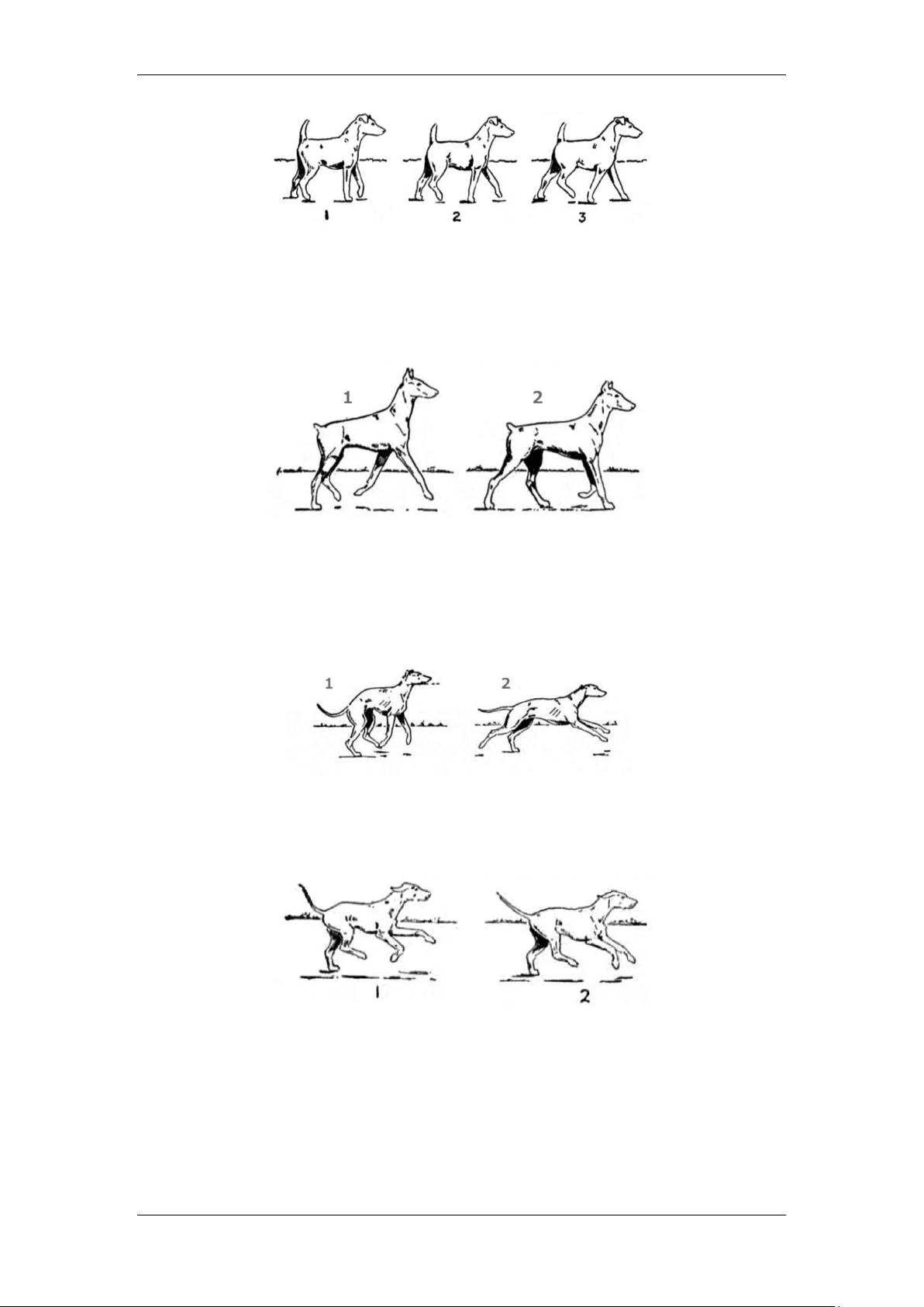
As shown in Figure 8, the leaping gait belongs to the running gait. Many quadruped mammals will
have this gait during running. It always lands on the ground with the front foot first, then lands on the
back foot, then leaves the ground with the front foot, and finally leaves the ground with the back foot.
This gait is special. It has both the time when the four feet are empty and the time when the four feet are landing at the same time. Figure 8: Bound gait
Running gait is the highest upper speed limit of a quadruped robot. Its walking time sequence
diagram is shown in Figure 9. When a quadruped robot adopts a running gait, only one leg can contact the ground at most.
Figure 9: Gallup/Run gait
3.3. Choice of gait
An understanding of the continuity of gait is required before choosing a gait. For the convenience of
understanding, the discontinuous gait is first introduced. The motion of the leg-type robot is divided
into the motion of the leg and the motion of the body. The discontinuous gait refers to the motion of the
leg and the motion of the body; Continuous gait is a gait in which the body is still moving during the lap.
Published by Francis Academic Press, UK -30-
Academic Journal of Engineering and Technology Science
ISSN 2616-5767 Vol.7, Issue 4: 25-35, DOI: 10.25236/AJETS.2024.070405
Once the definitions of continuous and discontinuous gait are understood, their respective
advantages and disadvantages are obvious. Because the continuous gait pace and body movements are
performed simultaneously, it moves significantly faster than the discontinuous gait. Compared with
continuous gait, discontinuous gait is less difficult to control, more stable and more suitable for complex pavement.
3.4. Model establishment and import
When the gait under various road conditions is selected, the simulation preparation will be started.
The 3D model can be established in Adams, but this operation is inconvenient. Therefore, in most cases,
the 3D model is created with other modeling software and then imported into Adams. The commonly
used 3D modeling software mainly includes Creo, Pro/E, SolidWorks, UG, etc. The modeling software
used in this paper is SolidWorks. The Adams version used in this article is 2020 and SolidWorks version 2023.
In SolidWorks, save the assembly file of the quadruped robot in the format of *. x_t. Note that the
model is saved as a solid and cannot be imported into Adams if saved as a shell. In Adams, the
generated *. x_t format file is imported, and the full path name of the *. x_t file cannot have Chinese.
3.5. Other parameters to be set during simulation
There are two parameters that must be set in the simulation: one is the material of the model and the
ground, and the other is the contact force between the four legs and the ground. If the material is not set,
the model will have no quality, resulting in simulation error. The material selection depends on the
actual situation. The material selected in this paper is steel.
During the simulation, the contact force between the four legs and the ground shall be added,
otherwise the simulation cannot be carried out. Refer to the parameter value range in the help file to
obtain the following setting parameters: Normal force select impact; Stiffness is set to 1.0E+05; Force
Experience is set to 1.3; Damping is set to 100; Penetration Depth is set to 0.1; The static coefficient is
set to 0.7; Dynamic Coefficient is set to 0.57; Friction Transition Velocity is set to 100; The
StiTransition Velocity is set to 1000.
It was found in the help file that after a collision between two solids, the Adams solver computes
the volume of the intersection. Therefore, there will be die piercing phenomenon in the experiment,
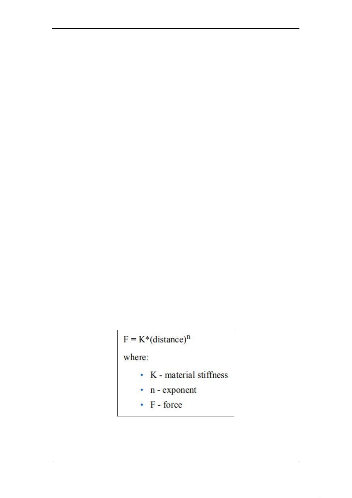
which can be understood as the deformation caused by the contact between two objects. As shown in
the formula in Figure 10, where F is the contact force generated by the material stiffness, distance is the
amount of deformation is a length value, n is the index, and K is the material stiffness. An example is
given in the help document: if a sphere is placed on a flat plate, the sphere and the flat plate will
intersect, the intersecting part is the combination of the sphere and the plane, and the line between the
center of mass of the intersecting part and the nearest point of the flat plate and the sphere will
inevitably pass through the center of the sphere, which proves that this kind of penetration is caused by the collision force.
Figure 10: Calculation formula of contact force due to stiffness in Adams
Published by Francis Academic Press, UK -31-
Academic Journal of Engineering and Technology Science
ISSN 2616-5767 Vol.7, Issue 4: 25-35, DOI: 10.25236/AJETS.2024.070405
3.6. Straight line travel
The straight line walking of the biomimetic quadruped robot adopts the diagonal gait, because the
diagonal gait is a kind of walking gait commonly used by quadruped animals. During the walking
process of the biomimetic quadruped robot, the two legs on the diagonal line are a group of diagonal
legs, the four legs can be divided into two groups of diagonal legs, the left front leg and the right rear
leg are Group A diagonal legs, and the left rear leg and the right front leg are Group B diagonal legs.
These two groups of diagonal leg joint swing angles have a fixed phase relationship, which can be
divided into support phase and swing phase. The motion mechanism of the diagonal gait of the
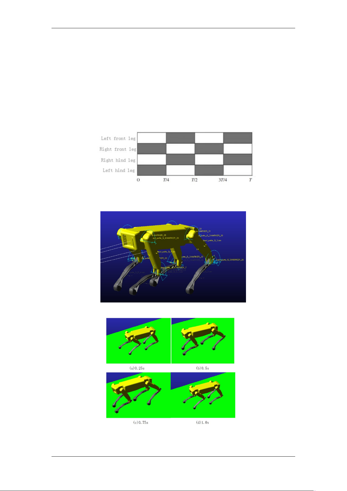
biomimetic quadruped robot is shown in Figure 11. The white square represents the leg landing of the
supporting phase, the black square represents the leg lifting of the swinging phase, and T is the gait cycle.
Figure 11: Diagonal gait mechanism of biomimetic quadruped robot
The virtual prototype model of the biomimetic quadruped robot is shown in Figure 12.
Figure 12: The Virtual Prototype Model of Bio-Inspired Quadropod Robot
Figure 13: Simulation gait of linear walking of biomimetic quadruped robot
As shown in Figure 13, when the biomimetic quadruped robot is in 0.25 s, the diagonal leg in
Published by Francis Academic Press, UK -32-
Academic Journal of Engineering and Technology Science
ISSN 2616-5767 Vol.7, Issue 4: 25-35, DOI: 10.25236/AJETS.2024.070405
Group A is the supporting phase of the current gait, and the diagonal leg in Group B is the swinging
phase of the current gait. The center of mass of the body moves forward 1/4 of the displacement of the
gait cycle. At 0.5 s, the diagonal leg in Group A is the swinging phase of the current gait, the diagonal
leg in Group B is the supporting phase of the current gait, and the center of mass of the fuselage moves
forward 1/4 of the displacement of the gait cycle. At 0.75 s and 1 s, the phase relationship of the
diagonal leg is the same as at 0.25 s and 0.5 s, respectively, to complete a straight walking cycle.
3.7. Motion simulation analysis
In the simulation process, IF function and sine function are used to drive the hip joint and knee joint
of the bionic quadruped robot, and the driving functions are as follows.
IF (expr1: expr2, expr3, expr4)
Where expr1 is the control variable; Expr2, expr3, and expr4 are all expressions.
The driving function of the left rear leg and right front leg knee joint is:
1d*IF(time-0.25:0, 0, -12.1*SIN(2*(time-0.25))
-ABS(12.1*SIN(2*(time-0.25))))
The driving function of the hip joint of the left rear leg and the right front leg is: 1d*7.1*SIN(2*PI*time+PI)
The driving function of the right rear leg and left front leg knee joint is:
1d*IF(time-0.25:-12.1*SIN(4*PI*(time-0.25)+PI), 0, 12.1*SIN(2*(time-0.25)+PI)
-ABS(12.1*SIN(2*(time-0.25)+PI)))
The driving function of the right rear leg and left front leg hip joint is: 1d*7.1*SIN(2*PI*time)
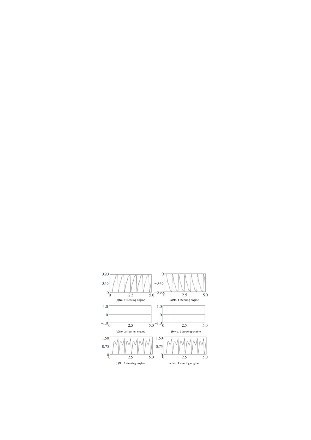
The driving function obtained through simulation is added to the joint of each leg, and the
movement angle of each steering engine when each leg is walking in a straight line is further
determined, and the change curve of the movement angle of the steering engine is obtained, as shown
in Figures 13 to 14, so as to judge the correctness of the straight-line walking gait of the biomimetic quadruped robot.
In Figure. 14 , the motion angles of No. 1 steering engine on the left front leg and right rear leg are
0.4887 ° at 5s, the motion angles of No. 2 steering engine are unchanged, and the motion angles of No.
3 steering engine are 1.452 °.
Figure 14: Steering engine movement angle of left front leg and right rear leg in straight walking
In Figure 15, the movable angles of No. 1 steering engine on the left rear leg and the right front leg
are 1.082 ° at 5s, the movable angles of No. 2 steering engine are unchanged, and the movable angles
of No. 3 steering engine are 1.431 °. The biomimetic quadruped robot achieves straight-line walking
Published by Francis Academic Press, UK -33-
Academic Journal of Engineering and Technology Science
ISSN 2616-5767 Vol.7, Issue 4: 25-35, DOI: 10.25236/AJETS.2024.070405
gait by alternately taking No. 1 steering engine and No. 3 steering engine as supporting phase and
swinging phase. During straight walking, the displacement of the center of mass of the whole machine
body changes with the forward displacement and lifting height of the foot.
Figure 15: Steering engine movement angle of left rear leg and right front leg in straight walking
The foot displacement and lift height curves of the left front leg are shown in Figure 16 and Figure
17, respectively. At 2s, the foot displacement of the left front leg was 136mm, and the foot lifting height was 150mm.
Figure 16: Change curve of foot displacement of left front leg in straight walking
Figure 17: Change curve of left front leg foot amplitude in straight walking
The linear walking gait simulated by the biomimetic quadruped robot can be judged to be consistent
with the actual walking gait according to the change of the movement angle of the steering engine of
each joint of the biomimetic quadruped robot and the change of the foot displacement and the lifting
height. However, according to the motion angle curve of joint steering engine, the joint steering engine shakes during motion.
Published by Francis Academic Press, UK -34-
Academic Journal of Engineering and Technology Science
ISSN 2616-5767 Vol.7, Issue 4: 25-35, DOI: 10.25236/AJETS.2024.070405 4. Conclusion
In order to solve the problem of unstable walking and smooth movement of quadruped robot, in this
paper, we designed a bionic quadruped robot and analyzed its leg structure and movement mode. We
used Solidworks and Adams for joint simulations, and constructed a physical prototype of gait testing
in biomimetic quadrupedal robots. We designed the mechanical structure of biomimetic quadruped
robots and developed a simulation model using Adams. Considering the problem of fluid movement, in
Adams, we propose and realize the gait of quadrupedal robot, so that the robot can run a rectangular
trajectory, and can cross some obstacles such as steps and obstacles. Next, we will further improve our
Adams simulation, and complete the construction of physical objects. Through the innovation of
control algorithm and artificial intelligence technology, the movement of the quadruped robot will be more smooth and coherent. References
[1] Qiuguo Zhu. On the development history, status and future of quadruped robot [J]. Hangzhou
Science & Technology, 2017(2):4.DOI: CNKI: SUN: HZKJ.0.2017-02-013.
[2] Zhou Yongning, Chen Rujie, Huang Junyi. Review of the development of quadruped robots [J].
Industrial science and technology innovation, 2021 (1): 4.
[3] Guardabrazo T A, Gonzalez d S P. Building an energetic model to evaluate and optimize power
consumption in walking robots [J]. Industrial Robot, 2004, 31(2):201-208. DOI: 10.1108/ 01439910410522874.
[4]Jiang Yiyang, Hao Fangming, Xue Jinbo, etc. A four-legged mechanical dog suitable for complex
terrain: CN202120668286.6[P]. CN216128363U[2024-06-14].
[5] Wang Runxiao, Zhong Yuhai. Research status and core Key technologies of quadruped Mobile
Robot [C] / / The 7th Annual Conference of National Local Mechanical Engineering Society and
Cross-strait Mechanical Technology Academic Forum in 2017.0[2024-05-23].
[6] Wang Rui. The current status study of quadruped robots [J]. Automotive World, 2020 (4): 2.
[7] Liang Qinqin. Outlook for the Innovative Application of Quped Robotics [J]. Integrated Circuit
Application, 2023, 40 (6): 356-357.
[8] Qiu Jun. Analysis of the research status of robot processing in China [J]. Mechanical Engineer, 2022 (3): 4.
[9] Li Shanshan, Wang Hongbo, Chen Jianyu, et al. Robot gait control algorithm and simulation of
new quadruads [J]. Journal of Military Engineering, 2023.
[10] Zhu Yaguang. Study on leg flexibility control of multifoot walking robot based on impedance
control [D]. Zhejiang University, 2014.
[11] Liu Chengju, Lin Limin, Chen Qijun. Adaptive walking control of a quadrupedal robot based on a
Rulkov neuron model [J]. Journal of Tongji University: Natural Science Edition, 2019, 47(8):9. DOI:
10. 11908/j. issn.0253-374x.2019.08.019.
[12] Wang Shiqing, Shan Xin, Liu Yichi. Development status and trend of quadruped robot [J]. Hunan
Paper making, 2020,049 (004): 227-228.
[13] He Wanheng, Ren Guoquan, Han Baohong, et al. Kinematic analysis and simulation based on a
quadruped robot [J]. Mechanical Engineer, 2023 (12): 23-26, 29.
[14] Zhang Wei, Tan Wenhao, Li Yibin. Development status and prospect of motion control in
quadruped robots based on deep reinforcement learning [J]. Journal of Shandong University: Medical
Edition, 2020, 58 (8): 61-66.
[15] Meng Jian, Liu Jinchang, Rong Xuewen, et al. Development status and prospect of quadruped
robot [J]. Science and Technology Herald, 2015, 33 (21): 59-63.
[16] Ma Biao. Structural design and analysis of a quadrupedal walking robot [D]. Beijing Jiaotong
University [2024-05-23].DOI:10.7666/d.y1080980.
[17]Wang Jun, Yin Yantao. Application of quadruped-walking Robots in Explosive Search and
Disposal Work. China Public Safety (Comprehensive Edition)[P] 2023,000(003), 25-28
[18] Wang Shiqing, Shan Xin, Liu Yichi. Development status and trend of quadruped robot [J]. Hunan
Paper making, 2020,049 (004): 227-228.
[19] Wang Runxiao, Zhong Yuhai. Research status and core Key technologies of quadruped Mobile
Robot [C] / / The 7th Annual Conference of National Local Mechanical Engineering Society and
Cross-strait Mechanical Technology Academic Forum in 2017.0[2024-05-23].
[20] Liu Yuntong, Li Xiaodan, Wang Xiaolei. Design and kinematic analysis of a new four-legged
robot leg mechanism [J]. Mechanical transmission, 2023, 47(8):83-89.
Published by Francis Academic Press, UK -35-
Document Outline
- 2.1. The concept and classification of biomimetic robots
- 2.2. Design and analysis of bionic quadruped robot
- 2.3. Leg structure analysis
- 2.4. The configuration types of four legs of bionic quadruped robot
- 3.1. The significance of gait planning
- 3.2. Gait introduction
- 3.3. Choice of gait
- 3.4. Model establishment and import
- 3.5. Other parameters to be set during simulation
- 3.6. Straight line travel
- 3.7. Motion simulation analysis