Interface Network Specification: Overview of File, Socket | Iot và ứng dụng | Học viện Công nghệ Bưu chính Viễn thông
Interface network can have only one service management end, namely the server end can only be installed in one PC. The client end is a card-issuing end installed in the card-issuing workstation or the card-reading/information-displaying workstation for issuing cards and displaying information. There is no limit on the number of client ends. It can be installed in all the workstations where card-issuing function is needed. In addition, different workstations can. Tài liệu được sưu tầm và soạn thảo dưới dạng file PDF để gửi tới các bạn cùng tham khảo, ôn tập đầy đủ kiến thức, chuẩn bị cho các buổi học thật tốt. Mời bạn đọc đón xem!
Môn: IoT và ứng dụng 143 tài liệu
Trường: Học viện Công Nghệ Bưu Chính Viễn Thông 1.8 K tài liệu
Tác giả:

Preview text:
ADEL Interface Network Specification
1. Overview of ADEL Lock Interface Network..................................................................................................... 2
1.1 Interface ..................................................................................................................................................... 2
1.1.1 Fidelio Interface ............................................................................................................................. 2
1.1.2 File Interface .................................................................................................................................. 2
1.1.3 Socket Interface ............................................................................................................................ 2
1.1.4 RS-232 Interface ........................................................................................................................... 2
1.2 Suitable Software ..................................................................................................................................... 2
1.3 Interface Network System ....................................................................................................................... 2
1.4 Running Environment .............................................................................................................................. 3
2. File Interface/Socket Interface Specifications ................................................................................................ 3
2.1 Data Protocol ............................................................................................................................................ 3
2.1.1 Control Character .......................................................................................................................... 3
2.1.2 Information Format........................................................................................................................ 3
2.2 Detailed Explanation of the Commands................................................................................................ 5
2.2.1 Guest Check-in/Check-out........................................................................................................... 5
2.2.2 Card Verification/Guest Card Reading Command ................................................................... 6
2.3 Data transferring specification for file interface.................................................................................... 6
2.4 Rules for Socket Interface Data Transmission..................................................................................... 6
3. Specification for RS-232 Interface ................................................................................................................... 7
3.1 Physical Layer........................................................................................................................................... 7
3.1.1 Electric Layer ................................................................................................................................. 7
3.1.2 Data Format ................................................................................................................................... 7
3.2 Data Protocol ............................................................................................................................................ 7
3.2.1 Control Character .......................................................................................................................... 7
3.2.2 Information Format........................................................................................................................ 7
3.3 Detailed Explanation ................................................................................................................................ 9
3.3.1 Guest Check-in/Guest Check-out ............................................................................................... 9
3.3.2 Card Verification/Guest Card Reading Command ................................................................. 10 1
Shenzhen Ideal Microelectronics Co., Ltd.
ADEL Interface Network Specification
1. Overview of ADEL Lock Interface Network 1.1 Interface
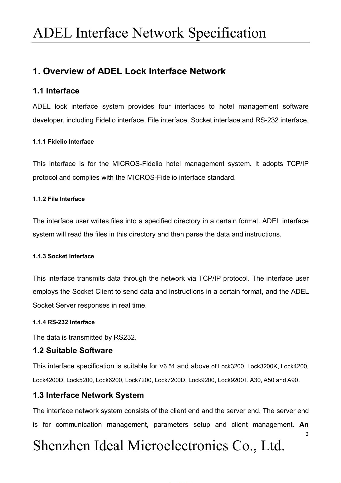
ADEL lock interface system provides four interfaces to hotel management software
developer, including Fidelio interface, File interface, Socket interface and RS-232 interface. 1.1.1 Fidelio Interface
This interface is for the MICROS-Fidelio hotel management system. It adopts TCP/IP
protocol and complies with the MICROS-Fidelio interface standard. 1.1.2 File Interface
The interface user writes files into a specified directory in a certain format. ADEL interface
system will read the files in this directory and then parse the data and instructions. 1.1.3 Socket Interface
This interface transmits data through the network via TCP/IP protocol. The interface user
employs the Socket Client to send data and instructions in a certain format, and the ADEL
Socket Server responses in real time. 1.1.4 RS-232 Interface
The data is transmitted by RS232. 1.2 Suitable Software
This interface specification is suitable for V6.51 and above of Lock3200, Lock3200K, Lock4200,
Lock4200D, Lock5200, Lock6200, Lock7200, Lock7200D, Lock9200, Lock9200T, A30, A50 and A90. 1.3 Interface Network System
The interface network system consists of the client end and the server end. The server end
is for communication management, parameters setup and client management. An 2
Shenzhen Ideal Microelectronics Co., Ltd.
ADEL Interface Network Specification
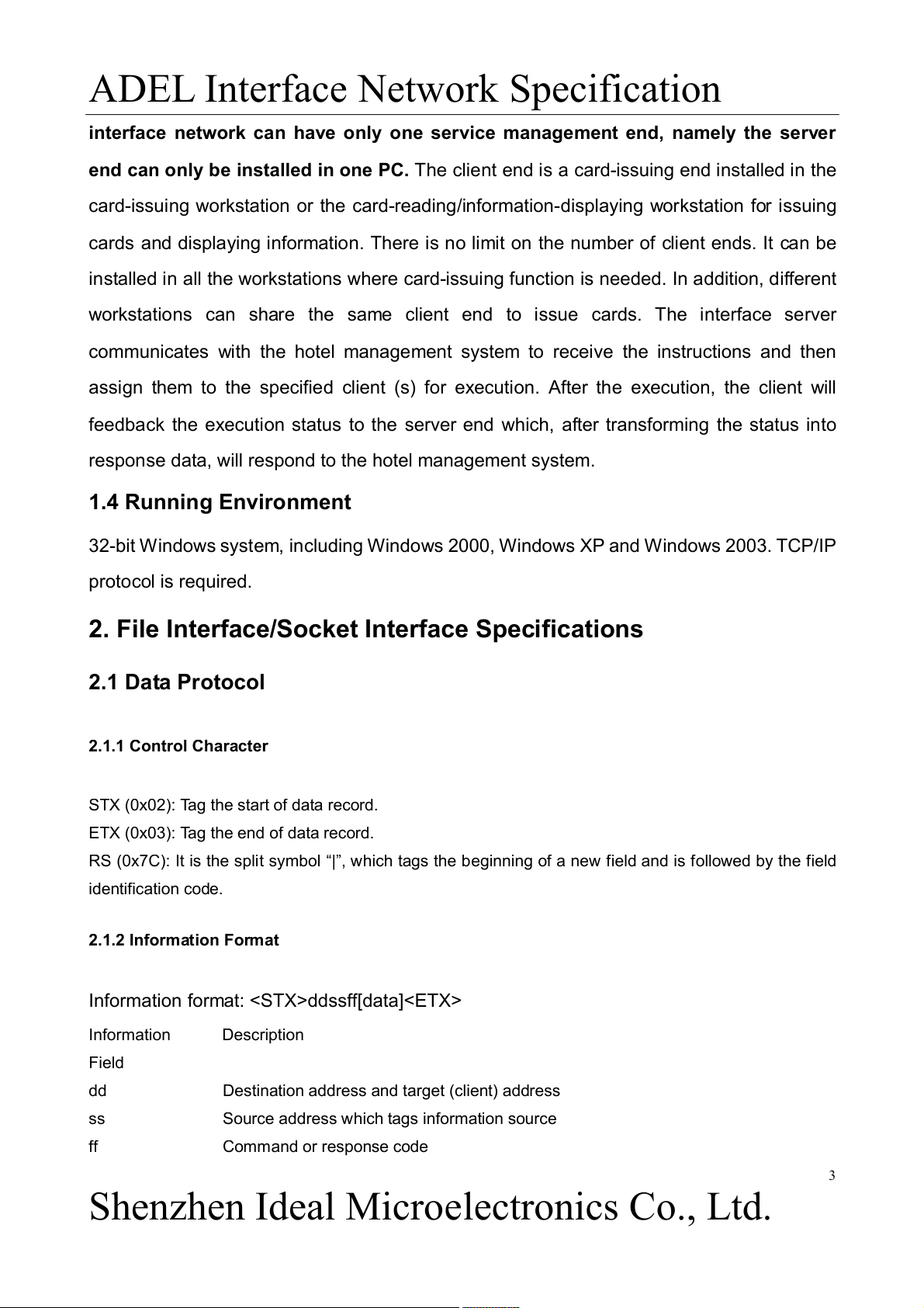
interface network can have only one service management end, namely the server
end can only be installed in one PC. The client end is a card-issuing end installed in the
card-issuing workstation or the card-reading/information-displaying workstation for issuing
cards and displaying information. There is no limit on the number of client ends. It can be
installed in all the workstations where card-issuing function is needed. In addition, different
workstations can share the same client end to issue cards. The interface server
communicates with the hotel management system to receive the instructions and then
assign them to the specified client (s) for execution. After the execution, the client will
feedback the execution status to the server end which, after transforming the status into
response data, will respond to the hotel management system. 1.4 Running Environment
32-bit Windows system, including Windows 2000, Windows XP and Windows 2003. TCP/IP protocol is required.
2. File Interface/Socket Interface Specifications 2.1 Data Protocol 2.1.1 Control Character
STX (0x02): Tag the start of data record.
ETX (0x03): Tag the end of data record.
RS (0x7C): It is the split symbol “|”, which tags the beginning of a new field and is followed by the field identification code. 2.1.2 Information Format
Information format: ddssff[data] Information Description Field dd
Destination address and target (client) address ss
Source address which tags information source ff Command or response code 3
Shenzhen Ideal Microelectronics Co., Ltd.
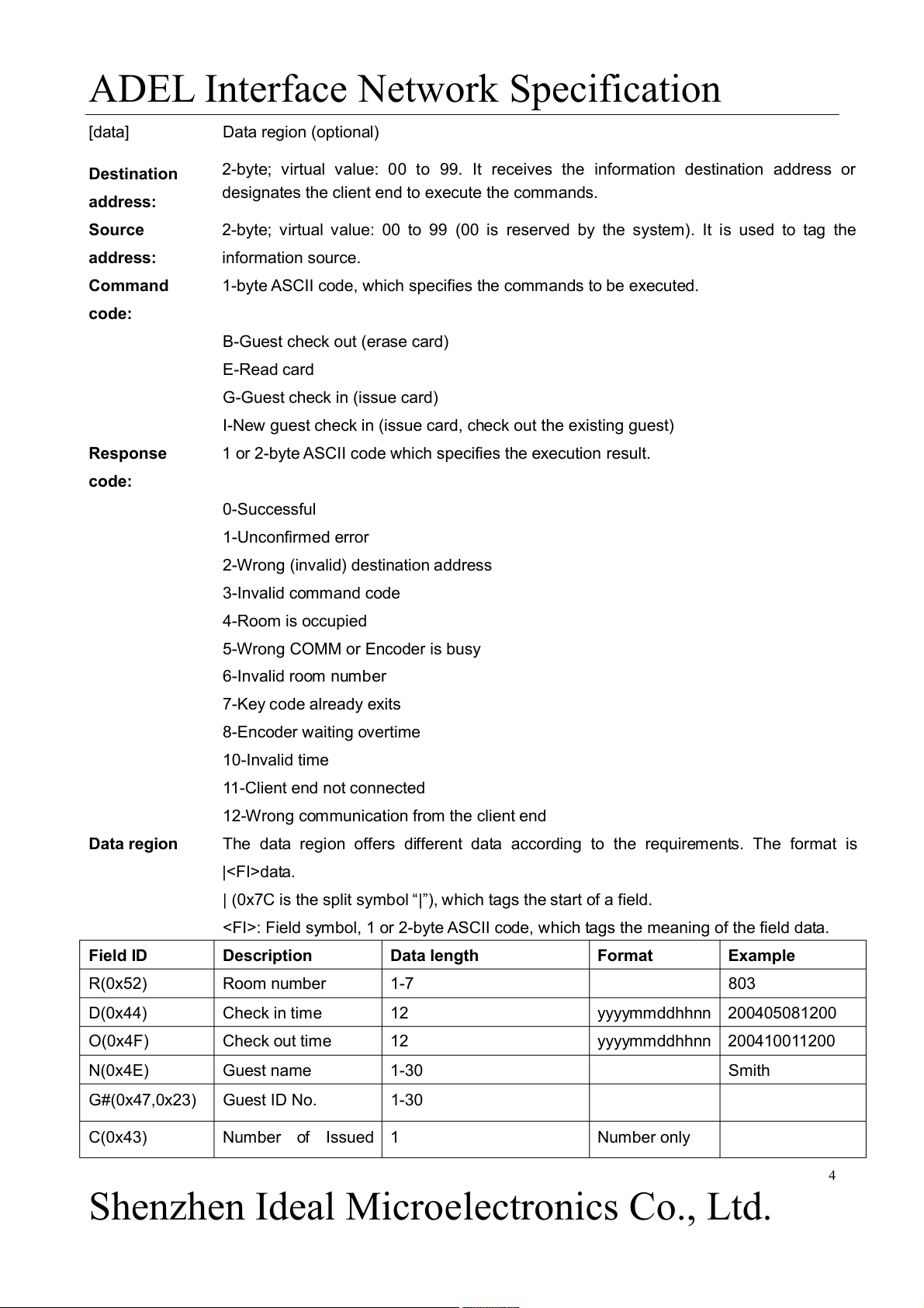
ADEL Interface Network Specification [data] Data region (optional) Destination
2-byte; virtual value: 00 to 99. It receives the information destination address or
designates the client end to execute the commands. address: Source
2-byte; virtual value: 00 to 99 (00 is reserved by the system). It is used to tag the address: information source. Command
1-byte ASCII code, which specifies the commands to be executed. code:
B-Guest check out (erase card) E-Read card G-Guest check in (issue card)
I-New guest check in (issue card, check out the existing guest) Response
1 or 2-byte ASCII code which specifies the execution result. code: 0-Successful 1-Unconfirmed error
2-Wrong (invalid) destination address 3-Invalid command code 4-Room is occupied
5-Wrong COMM or Encoder is busy 6-Invalid room number 7-Key code already exits 8-Encoder waiting overtime 10-Invalid time 11-Client end not connected
12-Wrong communication from the client end Data region
The data region offers different data according to the requirements. The format is |data.
| (0x7C is the split symbol “|”), which tags the start of a field.
: Field symbol, 1 or 2-byte ASCII code, which tags the meaning of the field data. Field ID Description Data length Format Example R(0x52) Room number 1-7 803 D(0x44) Check in time 12 yyyymmddhhnn 200405081200 O(0x4F) Check out time 12 yyyymmddhhnn 200410011200 N(0x4E) Guest name 1-30 Smith G#(0x47,0x23) Guest ID No. 1-30 C(0x43) Number of Issued 1 Number only 4
Shenzhen Ideal Microelectronics Co., Ltd.
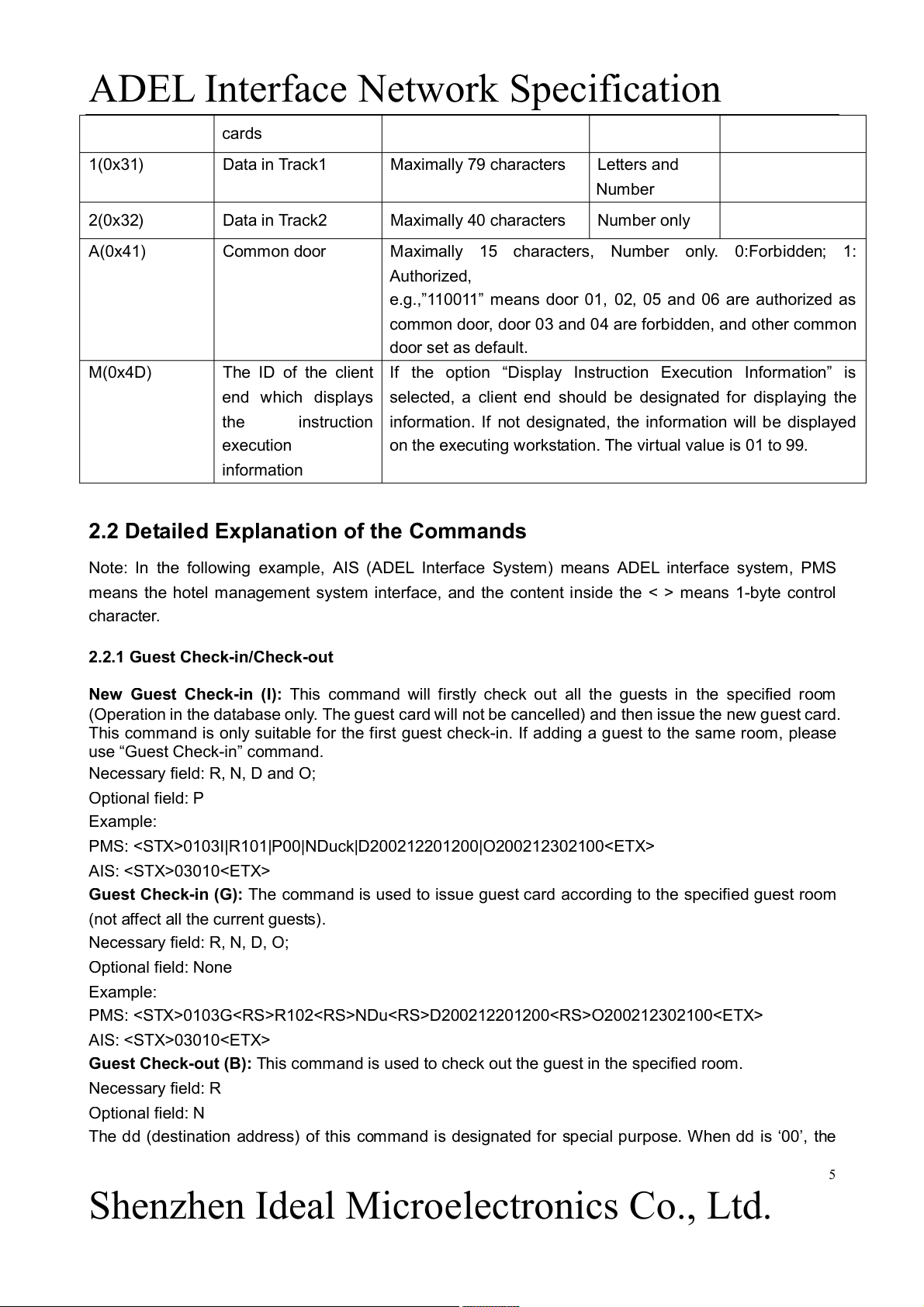
ADEL Interface Network Specification cards 1(0x31) Data in Track1 Maximally 79 characters Letters and Number 2(0x32) Data in Track2 Maximally 40 characters Number only A(0x41) Common door
Maximally 15 characters, Number only. 0:Forbidden; 1: Authorized,
e.g.,”110011” means door 01, 02, 05 and 06 are authorized as
common door, door 03 and 04 are forbidden, and other common door set as default. M(0x4D)
The ID of the client If the option “Display Instruction Execution Information” is
end which displays selected, a client end should be designated for displaying the the
instruction information. If not designated, the information will be displayed execution
on the executing workstation. The virtual value is 01 to 99. information
2.2 Detailed Explanation of the Commands
Note: In the following example, AIS (ADEL Interface System) means ADEL interface system, PMS
means the hotel management system interface, and the content inside the < > means 1-byte control character.
2.2.1 Guest Check-in/Check-out
New Guest Check-in (I): This command will firstly check out all the guests in the specified room
(Operation in the database only. The guest card will not be cancelled) and then issue the new guest card.
This command is only suitable for the first guest check-in. If adding a guest to the same room, please
use “Guest Check-in” command.
Necessary field: R, N, D and O; Optional field: P Example:
PMS: 0103I|R101|P00|NDuck|D200212201200|O200212302100 AIS: 03010
Guest Check-in (G): The command is used to issue guest card according to the specified guest room
(not affect all the current guests). Necessary field: R, N, D, O; Optional field: None Example:
PMS: 0103GR102NDuD200212201200O200212302100 AIS: 03010
Guest Check-out (B): This command is used to check out the guest in the specified room. Necessary field: R Optional field: N
The dd (destination address) of this command is designated for special purpose. When dd is ‘00’, the 5
Shenzhen Ideal Microelectronics Co., Ltd.
ADEL Interface Network Specification
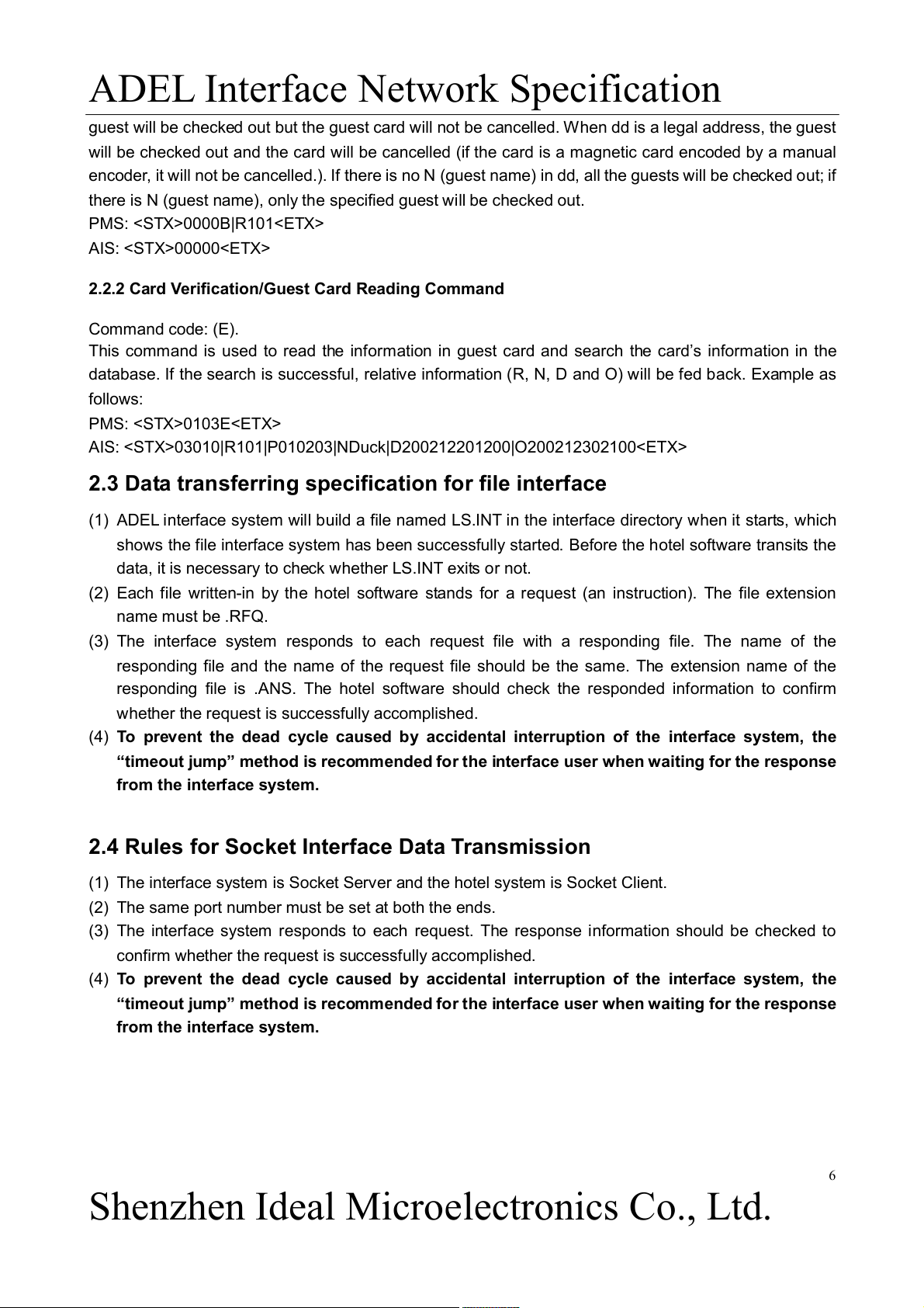
guest will be checked out but the guest card will not be cancelled. When dd is a legal address, the guest
will be checked out and the card will be cancelled (if the card is a magnetic card encoded by a manual
encoder, it will not be cancelled.). If there is no N (guest name) in dd, all the guests will be checked out; if
there is N (guest name), only the specified guest will be checked out. PMS: 0000B|R101 AIS: 00000
2.2.2 Card Verification/Guest Card Reading Command Command code: (E).
This command is used to read the information in guest card and search the card’s information in the
database. If the search is successful, relative information (R, N, D and O) will be fed back. Example as follows: PMS: 0103E
AIS: 03010|R101|P010203|NDuck|D200212201200|O200212302100
2.3 Data transferring specification for file interface
(1) ADEL interface system will build a file named LS.INT in the interface directory when it starts, which
shows the file interface system has been successfully started. Before the hotel software transits the
data, it is necessary to check whether LS.INT exits or not.
(2) Each file written-in by the hotel software stands for a request (an instruction). The file extension name must be .RFQ.
(3) The interface system responds to each request file with a responding file. The name of the
responding file and the name of the request file should be the same. The extension name of the
responding file is .ANS. The hotel software should check the responded information to confirm
whether the request is successfully accomplished.
(4) To prevent the dead cycle caused by accidental interruption of the interface system, the
“timeout jump” method is recommended for the interface user when waiting for the response from the interface system.
2.4 Rules for Socket Interface Data Transmission
(1) The interface system is Socket Server and the hotel system is Socket Client.
(2) The same port number must be set at both the ends.
(3) The interface system responds to each request. The response information should be checked to
confirm whether the request is successfully accomplished.
(4) To prevent the dead cycle caused by accidental interruption of the interface system, the
“timeout jump” method is recommended for the interface user when waiting for the response from the interface system. 6
Shenzhen Ideal Microelectronics Co., Ltd.
ADEL Interface Network Specification
3. Specification for RS-232 Interface 3.1 Physical Layer 3.1.1 Electric Layer
The EIA RS232C standard interface is employed to connect ADEL interface network system with the hotel management system. 3.1.2 Data Format
Data format: 1 start bit, 1 end bit, 8 data bits, no verification; The communication rate is from 2400bps to 19200bps. 3.2 Data Protocol 3.2.1 Control Character
STX (0x02): Tag the beginning of the data.
ETX (0x03): Tag the end of the data.
ENQ (0x05): Test the connection.
ACK (0x06): Response to the end which transmits the data and show that the transmitted data is correct.
NAK (0x15): Response to the end which transmits the data and show that the transmitted data is wrong.
RS (0x1E): Tag the beginning of the new field (region) and is followed by the field identification code. 3.2.2 Information Format
Information format: ddssff[data]cc
When the receiving end gets the information complying with the above format, it will respond with “ACK”
if the calculated verification is same as the received verification. Otherwise, it will respond with “NAK”.
The above responses (ACK and NAK) are applied to check the data integrality. They show neither the
data content nor whether the execution result is right or wrong. Information Field Description dd
Destination address, target (client) address ss
Source address which tags the information source ff Command or answer code [data] Data region (optional) Destination
2-byte; virtual value: 00 to 99. Receive the information destination address or
designate the client end to execute the commands. address: Source address:
2-byte; virtual value: 00 to 99 (00 is reserved by the system). Tag the information source. Command code:
1 byte ASCII code. Specify the command to be executed. 7
Shenzhen Ideal Microelectronics Co., Ltd.
ADEL Interface Network Specification
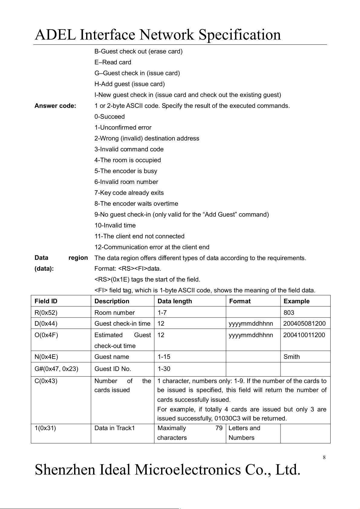
B-Guest check out (erase card) E–Read card
G–Guest check in (issue card) H-Add guest (issue card)
I-New guest check in (issue card and check out the existing guest) Answer code:
1 or 2-byte ASCII code. Specify the result of the executed commands. 0-Succeed 1-Unconfirmed error
2-Wrong (invalid) destination address 3-Invalid command code 4-The room is occupied 5-The encoder is busy 6-Invalid room number 7-Key code already exits 8-The encoder waits overtime
9-No guest check-in (only valid for the “Add Guest” command) 10-Invalid time
11-The client end not connected
12-Communication error at the client end Data
region The data region offers different types of data according to the requirements. (data): Format: data.
(0x1E) tags the start of the field.
field tag, which is 1-byte ASCII code, shows the meaning of the field data. Field ID Description Data length Format Example R(0x52) Room number 1-7 803 D(0x44) Guest check-in time 12 yyyymmddhhnn 200405081200 O(0x4F) Estimated Guest 12 yyyymmddhhnn 200410011200 check-out time N(0x4E) Guest name 1-15 Smith G#(0x47, 0x23) Guest ID No. 1-30 C(0x43) Number of
the 1 character, numbers only: 1-9. If the number of the cards to cards issued
be issued is specified, this field will return the number of cards successfully issued.
For example, if totally 4 cards are issued but only 3 are
issued successfully, 01030C3 will be returned. 1(0x31) Data in Track1 Maximally 79 Letters and characters Numbers 8
Shenzhen Ideal Microelectronics Co., Ltd.
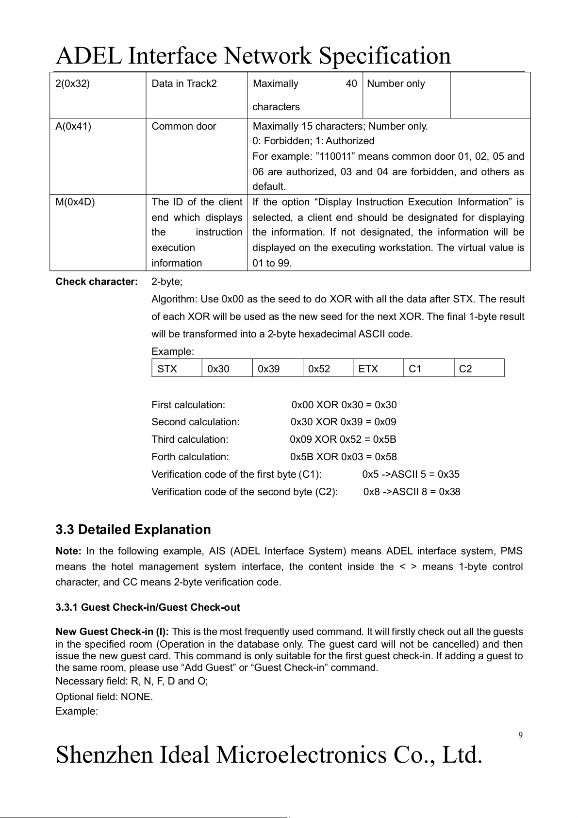
ADEL Interface Network Specification 2(0x32) Data in Track2 Maximally 40 Number only characters A(0x41) Common door
Maximally 15 characters; Number only. 0: Forbidden; 1: Authorized
For example: ”110011” means common door 01, 02, 05 and
06 are authorized, 03 and 04 are forbidden, and others as default. M(0x4D)
The ID of the client If the option “Display Instruction Execution Information” is
end which displays selected, a client end should be designated for displaying the
instruction the information. If not designated, the information will be execution
displayed on the executing workstation. The virtual value is information 01 to 99. Check character: 2-byte;
Algorithm: Use 0x00 as the seed to do XOR with all the data after STX. The result
of each XOR will be used as the new seed for the next XOR. The final 1-byte result
will be transformed into a 2-byte hexadecimal ASCII code. Example: STX 0x30 0x39 0x52 ETX C1 C2
First calculation: 0x00 XOR 0x30 = 0x30
Second calculation: 0x30 XOR 0x39 = 0x09
Third calculation: 0x09 XOR 0x52 = 0x5B
Forth calculation: 0x5B XOR 0x03 = 0x58
Verification code of the first byte (C1): 0x5 ->ASCII 5 = 0x35
Verification code of the second byte (C2): 0x8 ->ASCII 8 = 0x38 3.3 Detailed Explanation
Note: In the following example, AIS (ADEL Interface System) means ADEL interface system, PMS
means the hotel management system interface, the content inside the < > means 1-byte control
character, and CC means 2-byte verification code.
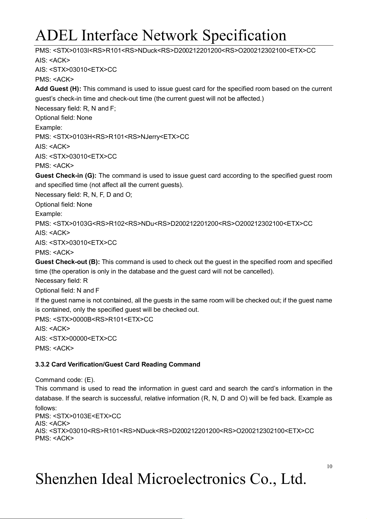
3.3.1 Guest Check-in/Guest Check-out
New Guest Check-in (I): This is the most frequently used command. It will firstly check out all the guests
in the specified room (Operation in the database only. The guest card will not be cancelled) and then
issue the new guest card. This command is only suitable for the first guest check-in. If adding a guest to
the same room, please use “Add Guest” or “Guest Check-in” command.
Necessary field: R, N, F, D and O; Optional field: NONE. Example: 9
Shenzhen Ideal Microelectronics Co., Ltd.
ADEL Interface Network Specification
PMS: 0103IR101NDuckD200212201200O200212302100CC AIS: AIS: 03010CC PMS:
Add Guest (H): This command is used to issue guest card for the specified room based on the current
guest’s check-in time and check-out time (the current guest will not be affected.) Necessary field: R, N and F; Optional field: None Example: PMS: 0103HR101NJerryCC AIS: AIS: 03010CC PMS:
Guest Check-in (G): The command is used to issue guest card according to the specified guest room
and specified time (not affect all the current guests).
Necessary field: R, N, F, D and O; Optional field: None Example:
PMS: 0103GR102NDuD200212201200O200212302100CC AIS: AIS: 03010CC PMS:
Guest Check-out (B): This command is used to check out the guest in the specified room and specified
time (the operation is only in the database and the guest card will not be cancelled). Necessary field: R Optional field: N and F
If the guest name is not contained, all the guests in the same room will be checked out; if the guest name
is contained, only the specified guest will be checked out. PMS: 0000BR101CC AIS: AIS: 00000CC PMS:
3.3.2 Card Verification/Guest Card Reading Command Command code: (E).
This command is used to read the information in guest card and search the card’s information in the
database. If the search is successful, relative information (R, N, D and O) will be fed back. Example as follows: PMS: 0103ECC AIS:
AIS: 03010R101NDuckD200212201200O200212302100CC PMS: 10
Shenzhen Ideal Microelectronics Co., Ltd.
Tài liệu liên quan:
-
Tóm tắt lý thuyết môn IoT và ứng dụng | Học viện Công Nghệ Bưu Chính Viễn Thông
23 12 -
Accelerated Corner-Detector Algorithms: GPU Implementations and Results | Iot và ứng dụng | Học viện Công nghệ Bưu chính Viễn thông
46 23 -
Đề xuất Dự án IoT: Thiết bị phát hiện chạm cho xe máy | Iot và ứng dụng | Học viện Công nghệ Bưu chính Viễn thông
35 18 -
Phân Tích và Giải Pháp FastAPI | Iot và ứng dụng | Học viện Công nghệ Bưu chính Viễn thông
30 15 -
Tăng cường pháp chế xã hội chủ nghĩa trong quản lý nhà nước | Iot và ứng dụng | Học viện Công nghệ Bưu chính Viễn thông
25 13