Introduction to automotive engineering handout môn Nhập môn kĩ thuật ô tô | Trường Đại học Bách Khoa Hà Nội
L2*G$
6#2
9
:
080d#
?)
CG$-
O9CG8)$-
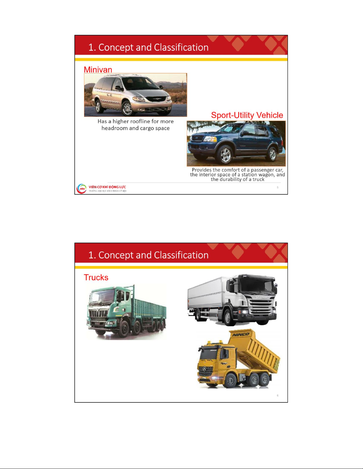
SCG+Minivan has a higher roofline for more headroom and cargo space. Sport-Utility Vehicle provides the comfort of a passenger car, the interior space of a station wagon, and the durability of a truck. Tài liệu được sưu tầm gồm 49 trang, giúp các bạn ôn luyện và phục vụ cho việc học tập, đạt kết quả tốt. Mời các bạn đón xem!
Môn: Nhập môn kĩ thuật ô tô 8 tài liệu
Trường: Đại học Bách Khoa Hà Nội 5.8 K tài liệu
Tác giả:
Preview text:
lOMoAR cPSD| 59595715 I N T R O D U C T I O N T O AUTOMOTIVE ENGINEERING
Assoc. Prof. Dr. Duong Ngoc Khanh
Dept. of Transportation Engineering
School of Mechanical Engineering khanh.duongngoc@hust.edu.vn 1 lOMoAR cPSD| 59595715 1
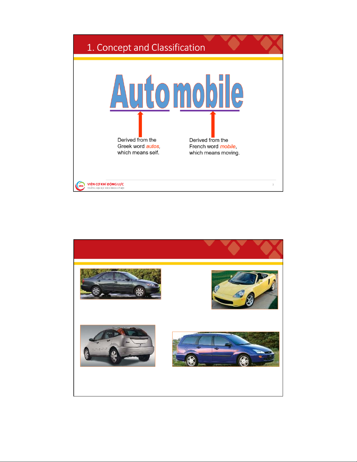
. C o n c e p t a n d C l a s s i f i c a t i o n Sedan Convertible
Uses center body pillars, or “B” pillars,
between the front and rear doors. A
hardtop does not use “B” pillars.
Uses a vinyl or cloth top that can be raised and lowered Hatchback Station Wagon
The large rear door allows easy
Provides a large rear interior compartment access when hauling items 4 lOMoAR cPSD| 59595715 lOMoAR cPSD| 59595715 2
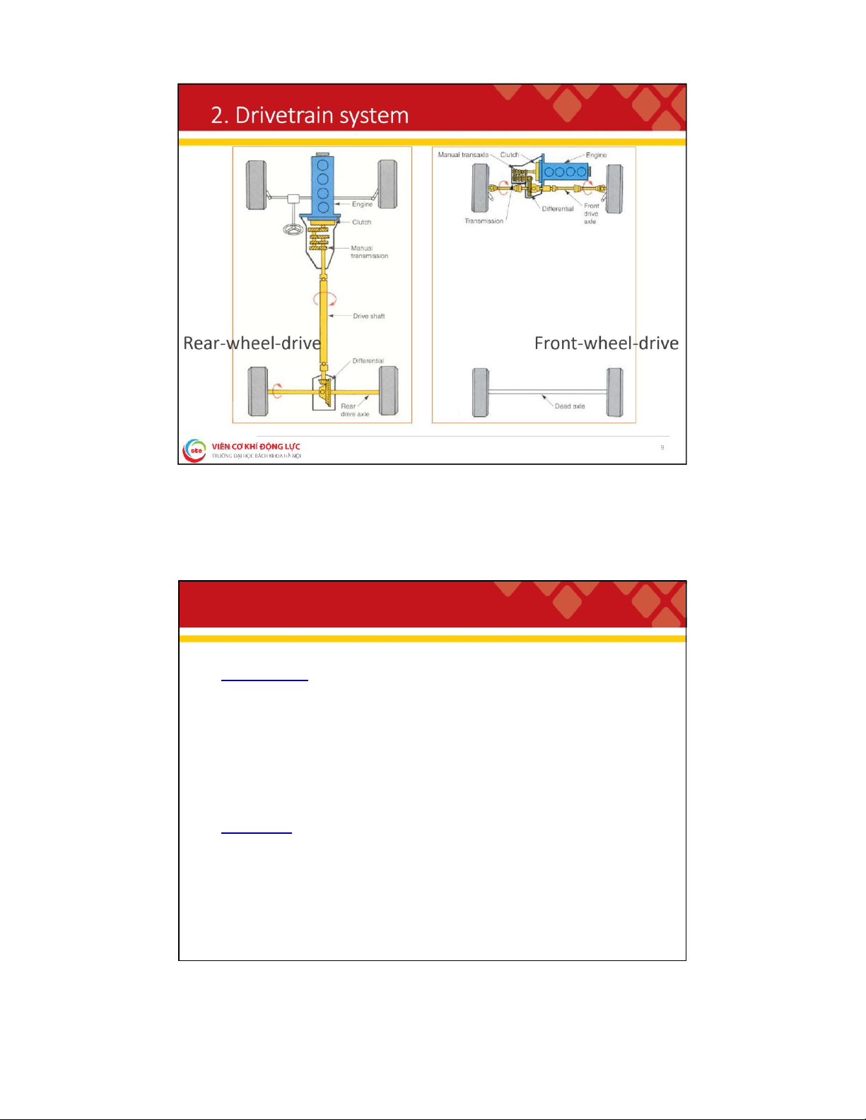
. D r i v e t r a i n s y s t e m Functions:
To couple the engine to the driving wheels;
To increase torque from the engine to the active wheels ;
To change the traction and speed at the wheels to suit the motion conditions;
To uncouple power transmission when needed ;
To reverse movement (reverse gear) . Components: Clutch; Transmission/Transaxle; Propel er shaft; Front/Rear axle. 8 lOMoAR cPSD| 59595715 2 . 1 . C l u t c h Functions:
❑ Used to connect and disconnect the engine and manual transmission or transaxle;
❑ Allows the driver to control power flow between the engine and transmission or transaxle;
❑ To serves as a safety device of the drivetrain system. Classify:
❑ Clutch (Manual transmission);
❑ Torque converter (Automatic transmission); ❑ Others. 10 lOMoAR cPSD| 59595715 2
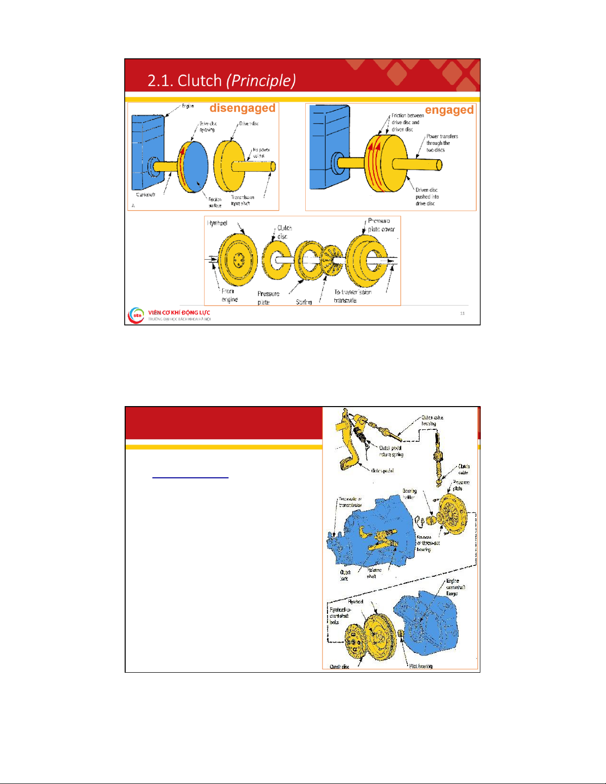
. 1 . C l u t c h ( B a s i c P a r t s ) Components: • pilot bearing • flywheel • clutch disc • pressure plate • release bearing
• clutch housing (bell housing) • clutch fork • clutch release mechanisms • clutch start switch 12 lOMoAR cPSD| 59595715 2
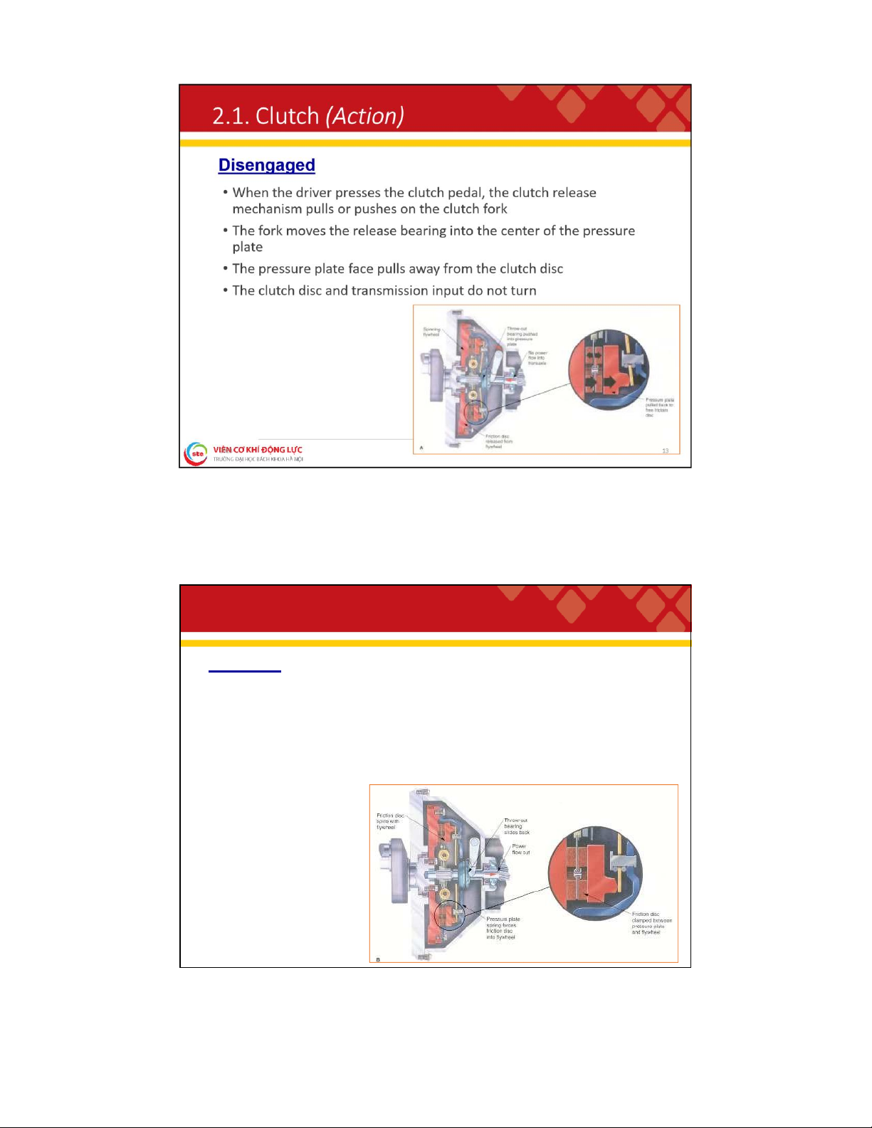
. 1 . C l u t c h ( A c t i o n ) Engaged
• When the driver releases the clutch pedal, the spring pressure
inside the pressure plate pushes forward on the clutch disc
• This locks the flywheel, disc, pressure plate, and transmission input together
• The engine rotates the transmission input 14 lOMoAR cPSD| 59595715 2
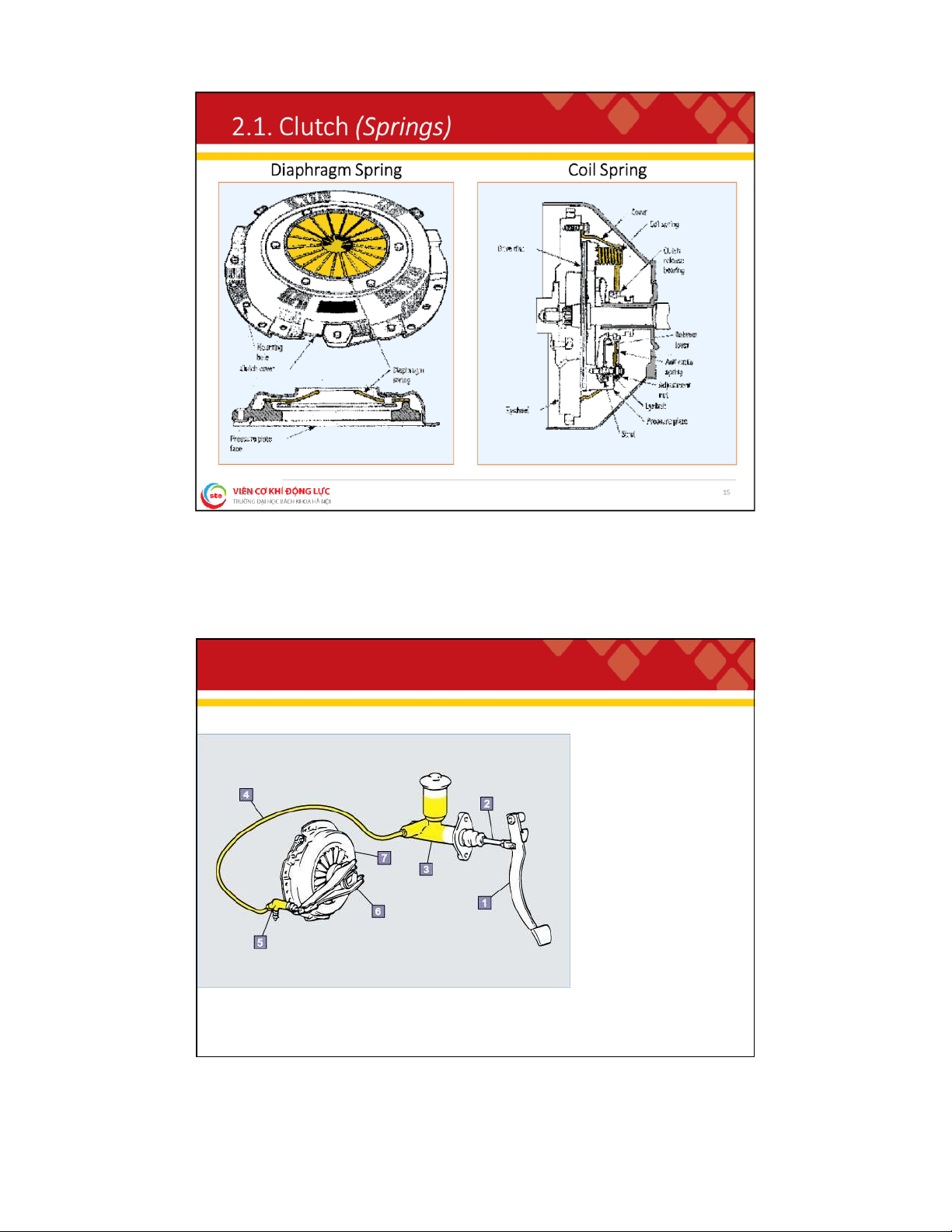
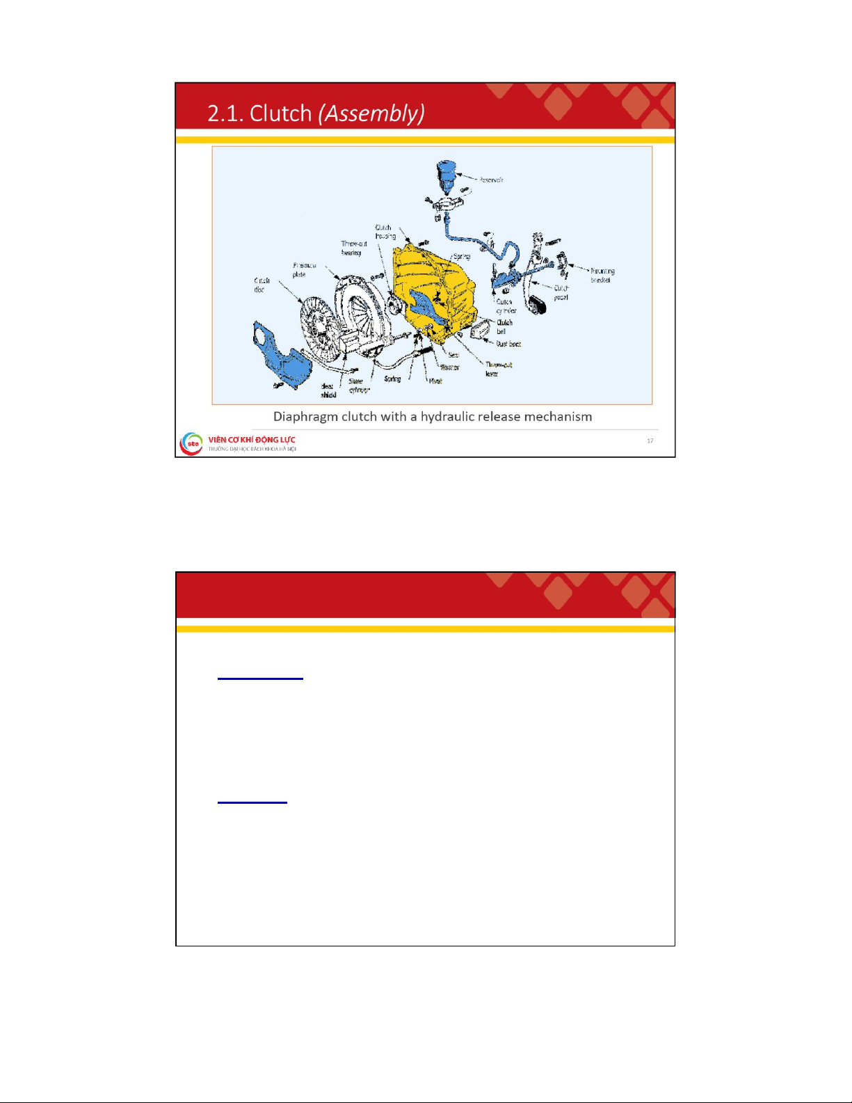
. 1 . C l u t c h ( H y d r a u l i c R e l e a s e M e c h a n i s m ) ❑ Uses a simple hydraulic circuit to transfer clutch pedal action to the clutch fork. ❑ Components: • clutch pedal • clutch cylinder • hydraulic line • slave cylinder • release fork/level 16 lOMoAR cPSD| 59595715 2
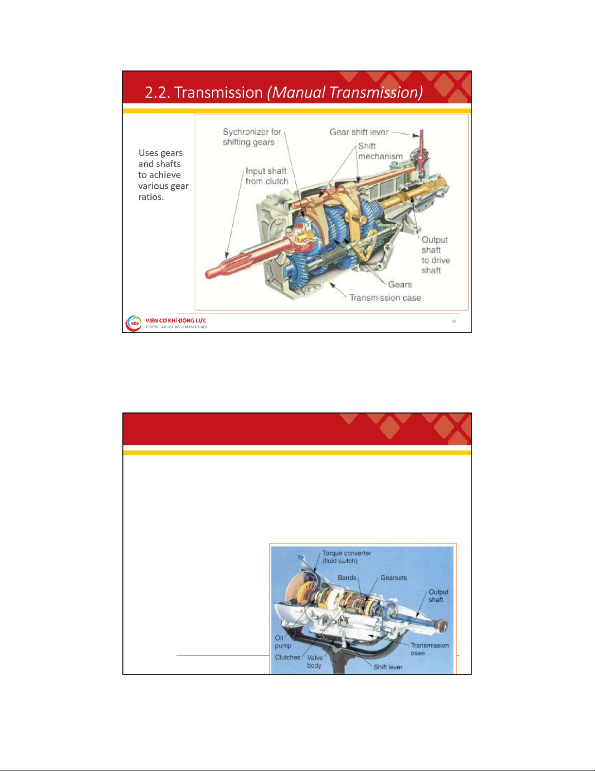
. 2 . T r a n s m i s s i o n Functions:
❑ Uses various gear combinations (ratios), to multiply engine speed
and torque to accommodate driving conditions;
❑ To uncouple power transmission when needed;
❑ To provide a reverse gear. Classify: ❑ Manual Transmission (MT)
❑ Automotive Transmission (AT) 18 lOMoAR cPSD| 59595715 2
. 2 . T r a n s m i s s i o n ( A u t o m a t i c T r a n s m i s s i o n )
❑ Does not have to be shifted by the driver;
❑ Uses an internal hydraulic system and, in most cases, electronic controls to shift gears;
❑ Internal clutches or bands control gearsets to provide various gear ratios;
❑ Input shaft is connected to the engine crankshaft through a torque converter. 20 lOMoAR cPSD| 59595715 2
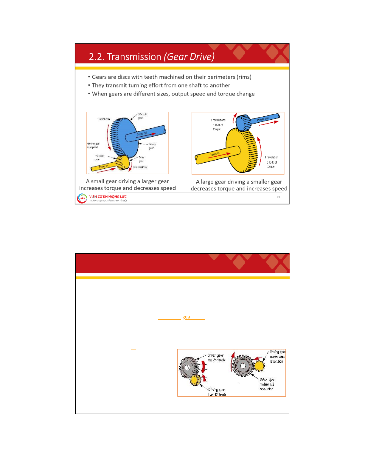
. 2 . T r a n s m i s s i o n ( G e a r R a t i o )
• The number of revolutions a drive gear must turn before the driven gear completes one revolution
• Calculated by dividing the number of teeth on the driven gear by the
number of teeth on the drive gear Gear Ratio = # of driven g ear teeth # of drive gear teeth
Example: If the drive gear has 12 teeth and the driven gear has 24
teeth, the gear ratio is two-to-one Gear Ratio = 24 = 2, written 2:1 12 22 lOMoAR cPSD| 59595715 2
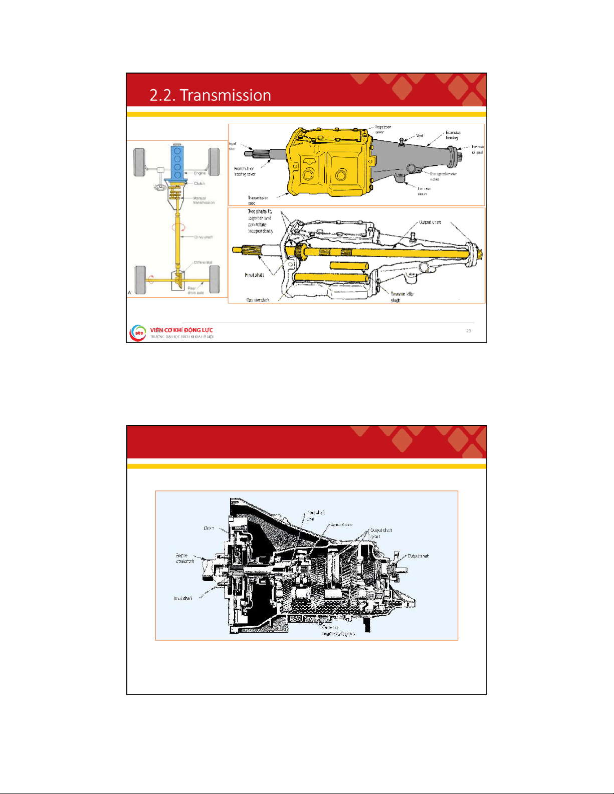
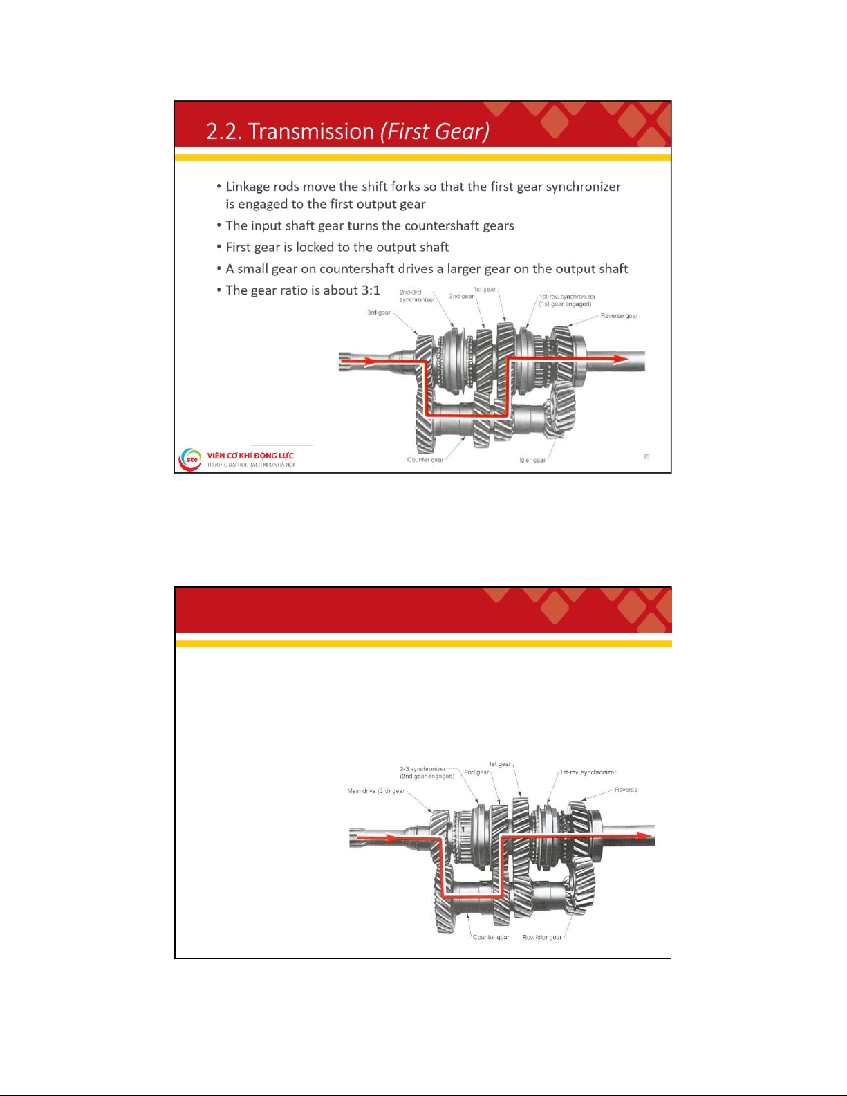
. 2 . T r a n s m i s s i o n ( T r a n s m i s s i o n G e a r s )
The input shaft gear turns the countershaft gears, which then turn the output shaft gears 24 lOMoAR cPSD| 59595715 2
. 2 . T r a n s m i s s i o n ( S e c o n d G e a r )
• The first gear synchronizer is slid away from the first gear
• The second-third synchronizer is then engaged
• Power flow is through the second gear on the output shaft
• The gear ratio is about 2:1 26 lOMoAR cPSD| 59595715 2
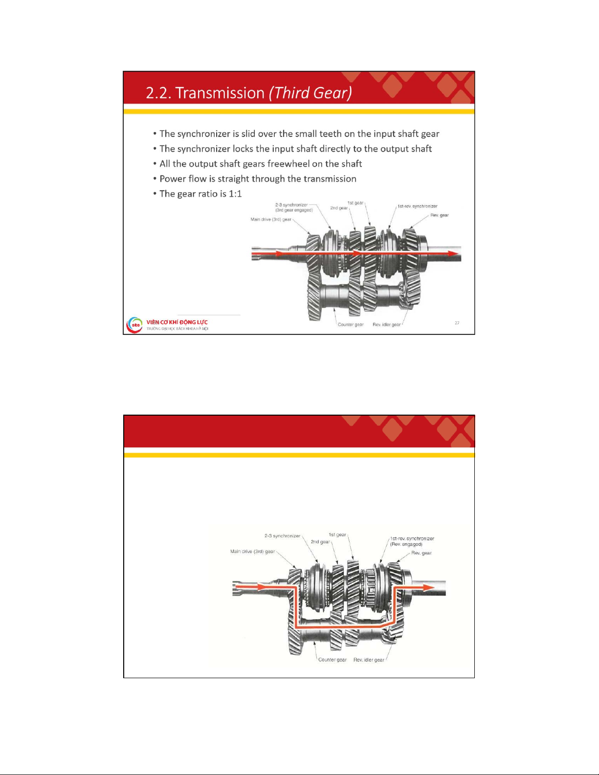
. 2 . T r a n s m i s s i o n ( R e v e r s e G e a r )
• The synchronizer is moved into the reverse gear on the output shaft,
locking the gear to the output shaft
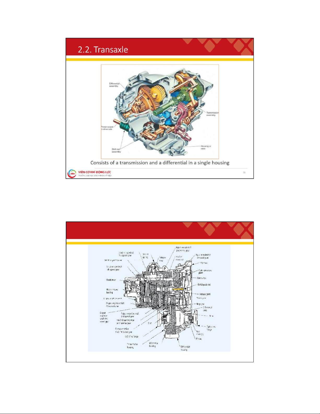
• Power flows through the countershaft, reverse idler gear, reverse gear, and to the output shaft 28 lOMoAR cPSD| 59595715 2 . 2 . T r a n s a x l e
Short drive axle assemblies connect the
transaxle output to the hubs and wheels 30 lOMoAR cPSD| 59595715 2
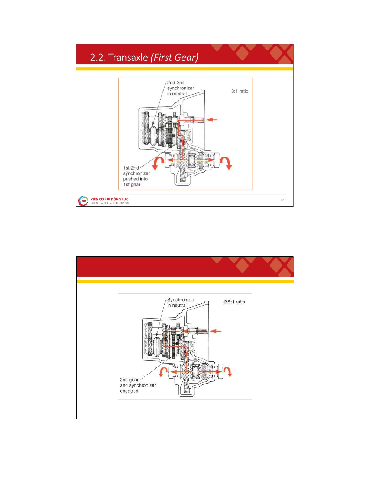
. 2 . T r a n s a x l e ( M a n u a l T r a n s a x l e ) 32 lOMoAR cPSD| 59595715 2
. 2 . T r a n s a x l e ( S e c o n d G e a r ) 34 lOMoAR cPSD| 59595715 2
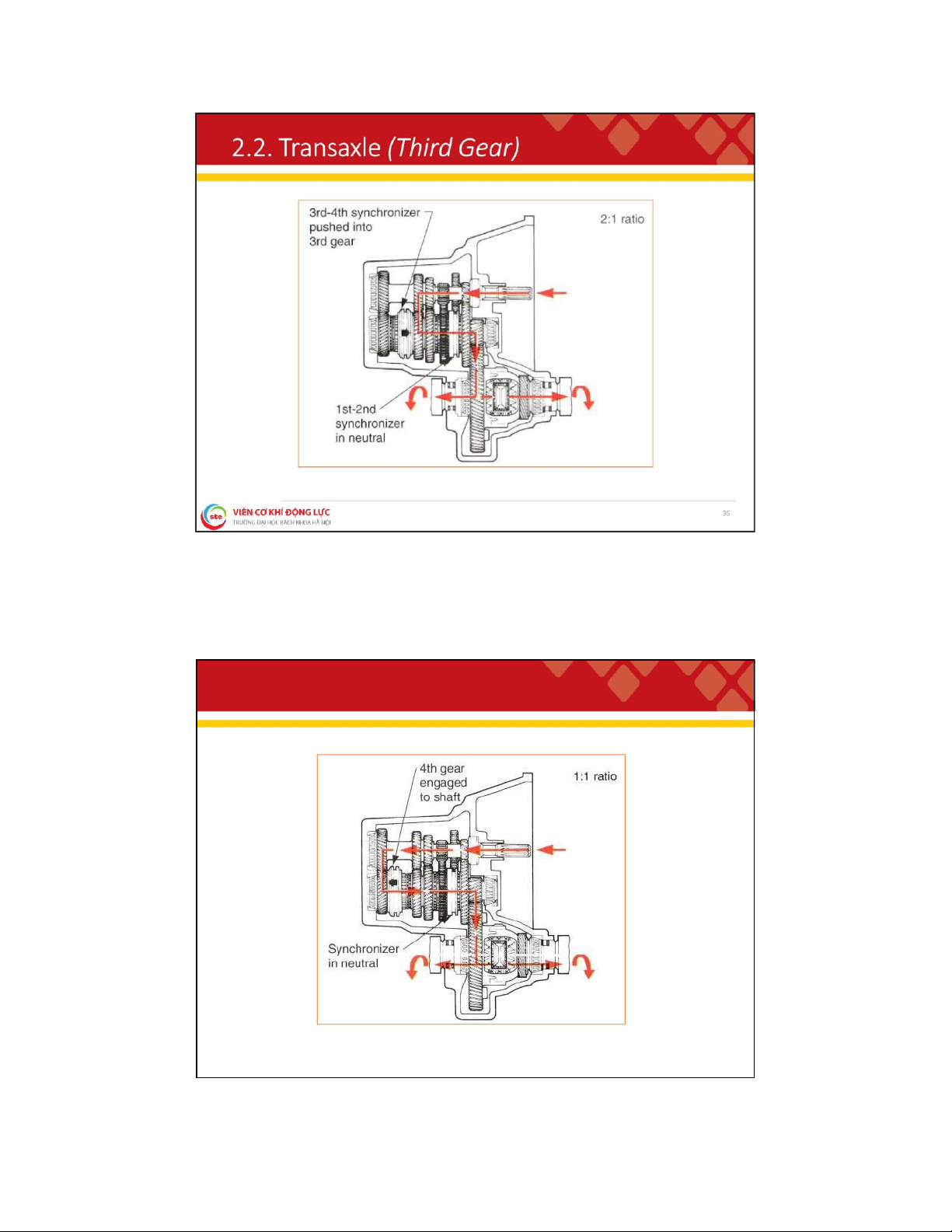
. 2 . T r a n s a x l e ( F o u r t h G e a r ) 36 lOMoAR cPSD| 59595715 2
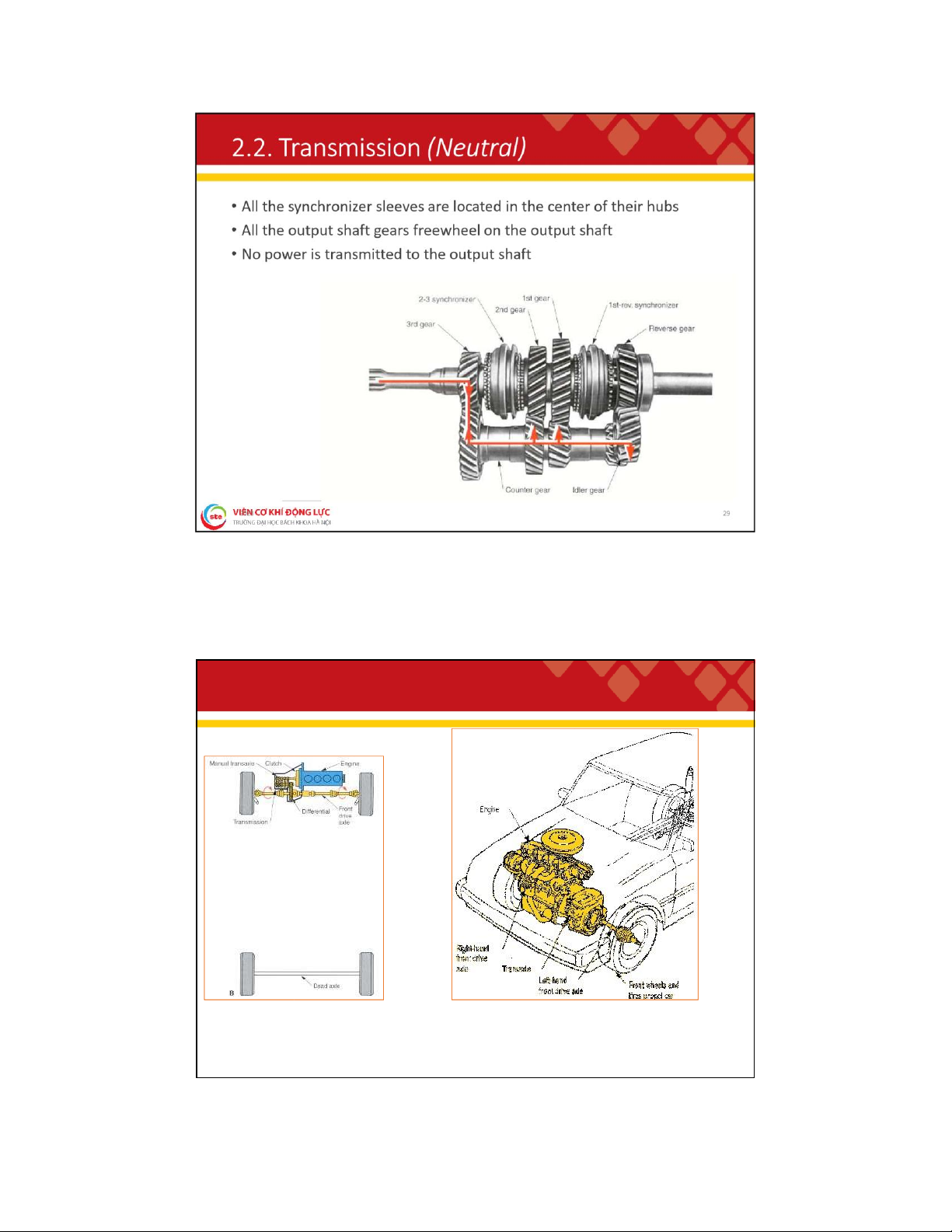
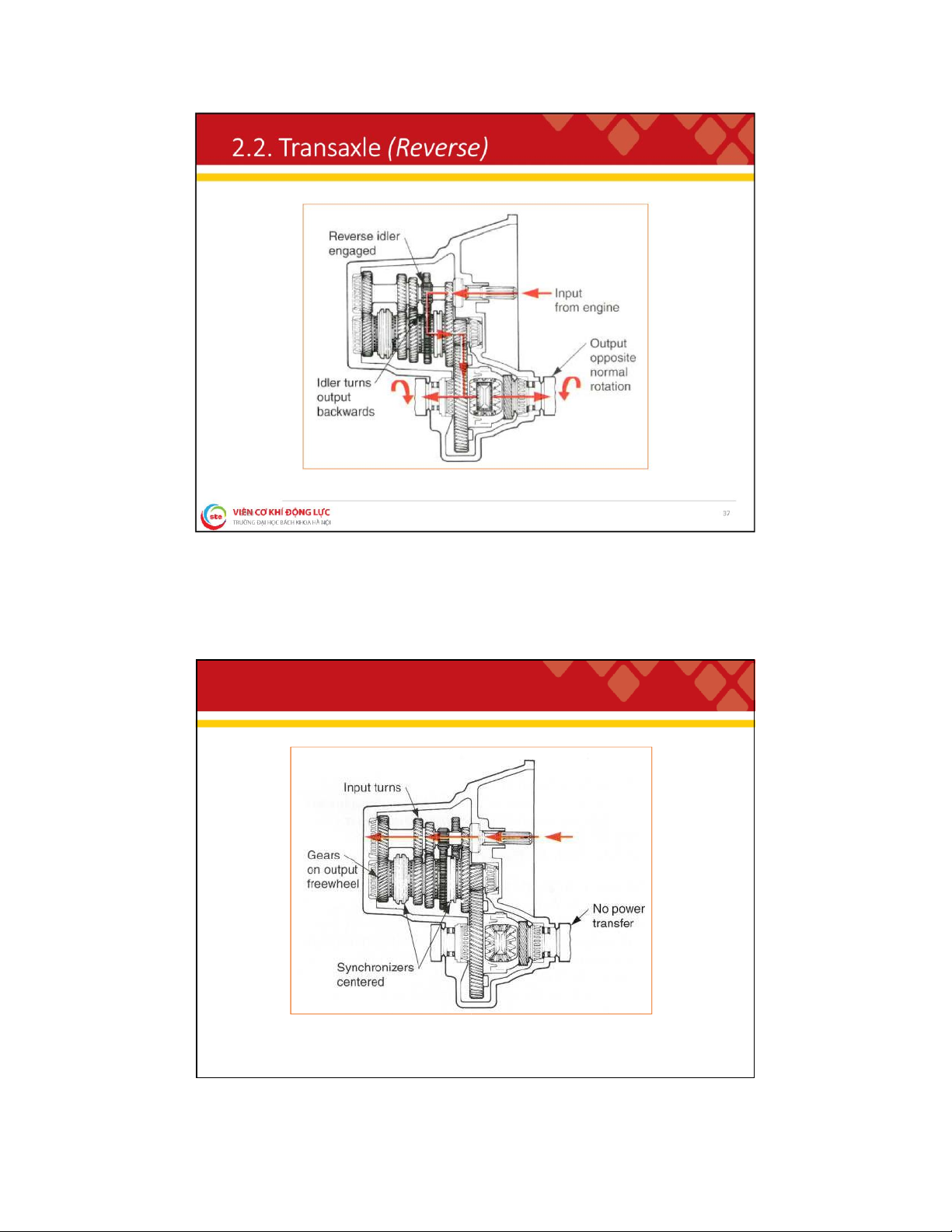
. 2 . T r a n s a x l e ( N e u t r a l ) 38 lOMoAR cPSD| 59595715 2
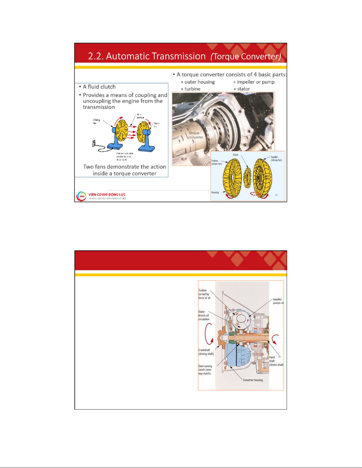
. 2 . A ut o m a t i c T r a n s m i s s i o n ( T o r q u e C o n v e r t e r ) ❑ Impeller • Driven by the engine
• Integral part of the housing
• Produces oil movement within the converter ❑ Turbine • Driven by the impeller
• Splined to the transmission input shaft
• Fits in the front of the housing
• Oil is the only connection between the impeller and the turbine ❑ Stator • Improves oil circulation
• Increases efficiency and torque by directing the oil flow toward the turbine
• Helps make use of nearly all the force produced by the moving oil
• Located between the impeller and the turbine, mounted on a one-way clutch 40
Tài liệu liên quan:
-
GIÁO TRÌNH - Thiết kế tính toán ô tô (PGSTS Nguyễn Trọng Hoan)
57 29 -
Tiểu luận đồ án nghiên cứu thiết kế tính toán trục các đăng khác tốc trên ô tô con
53 27 -

Bài giảng Kỹ thuật bảo dưỡng, sửa chữa ô tô môn Nhập môn kĩ thuật ô tô | Trường Đại học Bách Khoa Hà Nội
117 59 -
Chương trình Đào tạo kỹ thuật ô tô (Thạc sĩ) - Cơ khí động lực môn Nhập môn kĩ thuật ô tô | Trường Đại học Bách Khoa Hà Nội
94 47