Mạng máy tính - Bài tập chương 1: Các vấn đề và câu hỏi ôn tập. Môn Mạng máy tính (ĐHCN) | Trường Đại học Công nghệ, Đại học Quốc gia Hà Nội.
Homework Problems and Questions
Chapter 1 Review questions
SECTION 1.1 R1:
- A host and an end system are the terms which are used interchangeably. There is no significant difference between a host and an end system. A host is an end system. In the internet, all devices are called hosts and end systems.
- Following is the list of different types of end systems:
• Desk top PCs
• Workstations
• Web servers
• Email servers
• Personal digital assistants (PDAs)
• TVs
• Mobile computers
• Cell phones etc.
- Yes, web server is an end system. Web server is a program that serves the requests of the user in the form of web pages.
Mạng máy tính - Bài tập chương 1: Các vấn đề và câu hỏi ôn tập. Môn Mạng máy tính (ĐHCN) | Trường Đại học Công nghệ, Đại học Quốc gia Hà Nội.
Tài liệu gồm 38 trang giúp bạn tham khảo, củng cố kiến thức và ôn tập đạt kết quả cao trong kỳ thi sắp tới. Mời bạn đọc đón xem!
Môn: Mạng máy tính (ĐHCN) 12 tài liệu
Trường: Trường Đại học Công nghệ, Đại học Quốc gia Hà Nội 823 tài liệu
Tác giả:


Preview text:
lOMoAR cPSD| 58833082
Homework Problems and Questions Chapter 1 Review questions SECTION 1.1 R1:
- A host and an end system are the terms which are used interchangeably. There is no
significant difference between a host and an end system. A host is an end system. In
the internet, all devices are called hosts and end systems.
- Following is the list of different types of end systems: • Desk top PCs • Workstations • Web servers • Email servers
• Personal digital assistants (PDAs) • TVs • Mobile computers • Cell phones etc.
- Yes, web server is an end system. Web server is a program that serves the requests of
the user in the form of web pages. R2:
A protocol is set of rules that are to be followed to perform an activity or task.
• A diplomatic protocol is set of rules that are specified by the heads of nations or countries.
• A diplomatic protocol is to be followed for making deals with other countries.
• It is an art of conducting negotiations between the representatives of different countries. R3:
A protocol is set of rules that are to be followed to perform an activity or task. In
network terminology, a protocol is a set of rules that are followed to control the
exchange of data between two communicating devices.
Standards for protocols are important because they specify the manner and order of
sending and receiving data between the communicating devices. SECTION 1.2 R4:
- The following are the six access technologies:
1. Digital Subscriber Line over telephone line 2. Cable internet access 3. Fiber to the home (FTTH)
4. Dial-up modem over telephone line 5. Ethernet lOMoAR cPSD| 58833082 • 6. Wi-Fi
- Classification of each access technologies as home access, enterprise access or widearea wireless access:
• Digital Subscriber Line over telephone line can be classified as the one that is used for home access.
• Cable internet access can be classified as the one that is used for home access.
• Fiber to the home (FTTH) can be classified as the one that is used for home
access. • Dial-up modem over telephone line can be classified as the one that is used for home access.
• Ethernet can be classified as the one that is used for home access as well as enterprise access.
• Wi-Fi can be classified as the one that is used for home access, enterprise access
as well as wide-are wireless access.
• Third-generation (3G) wireless and Long-Term Evolution (LTE) are used for
widearea wireless access. They are the access technologies used in mobiles. R5:
- The HFC (Hybrid Fiber Coax) is used for cable Internet access. HFC uses both coaxial
cables and fiber. In downstream channel of HFC, every packet travels from head end
to every home. In upstream channel of HFC, every packet sent by a home travels to
head end. Since the cable Internet uses a shared medium to transmit the packets, the
HFC transmission rate is shared among the users.
- Collision is occurred when multiple sources sent the packets simultaneously into the
shared medium. For example, in upstream channel of HFC, multiple homes sent
packets to head end simultaneously. Thus, collisions are possible in upstream channel.
But in downstream, every packet is sent by only single source called head end. Thus,
collisions are not possible in downstream. R6:
The residential access technologies in a city vary with time and legal boundaries of the
country. The technology is evolving day to day. The nature and characteristics of the
residential access technologies keeps on changing by time.
(Note: The information related to the type of access available, advertised downstream
rate, upstream rate, and monthly price changes with time and location. So, the answer
may vary with time and location.)
The four residential access technologies available in a city at a particular point of time
and at certain location are as follows:
1. Dial-up modem over telephone line:
• Advertised data transfer rate for downstream and upstream Dial-up modems is 56Kbps. lOMoAR cPSD| 58833082
• The transmission rate of dial-up modems is dedicated broadcast medium. • Monthly price is $76.81.
2. Digital subscriber line (DSL) over telephone line:
• The advertised data transfer rate for downstream ranges from 12 to 55 Mbps.
• The advertised data transfer rate for upstream ranges from 1.6 to 20 Mbps.
• The transmission rate of DSL is dedicated broadcast medium. • Monthly price is $50. 3. Cable modem:
• The advertised data transfer rate for downstream is a maximum of 30 Mbps.
The advertised data transfer rate for upstream is a maximum of 2 Mbps.
• The transmission rate of cable modem is shared broadcast medium.
• Monthly price ranges from $3 to $5. 4. fiber-to-the-home:
• The advertised data transfer rate for downstream ranges from 10 to 20 Mbps.
• The advertised data transfer rate for upstream ranges from 2 to 10 Mbps.
• The transmission rate of FTTH is shared broadcast medium.
• Monthly price is $80 to $100. R7:
Ethernet is the most commonly used access technology in universities, schools,
corporate sectors and for home networks.
The transmission rates of Ethernet LANs can be 10 Mbps, 100 Mbps, 1 Gbps and 10
Gbps. For an Ethernet LANs with a transmission rate of 10 Mbps, a user can
continuously transmit data at the rate of 10Mbps if he is the only person using the LAN.
If there are more number of users using the LAN and wants to transmit data, then each
user cannot continuously transmit data at the rate of 10 Mbps. The same is applicable
for the other transmission rates. R8:
- Ethernet is the most commonly used access technology in universities, schools,
corporate sectors and for home networks.
- Following are some of the physical media that Ethernet can run over: •Twisted-pair copper wire • Thin coaxial cable • Thick coaxial cable • Fiber-optics cable
• Terrestrial radio channels
• Satellite radio channels R9: - Dial-up modems:
• The transmission rate of Dial-up modems is 56Kbps. lOMoAR cPSD| 58833082 •
• The transmission rate of dial-up modems is dedicated broadcast medium. -
Hybrid fiber-coaxial cable (HFC):
• HFC is having transmission rates for the downstream channel is 10 Mbps to 30 Mbps.
• Upstream channel is less than the downstream channel.
• The transmission rate of HFC is shared broadcast medium. - Digital subscriber line (DSL):
• The transmission rate of DSL is less than 5Mbps.
• The transmission rate of DSL is dedicated broadcast medium. - Fiber to the home (FTTH):
• The transmission rate of FTTH is 20Mbps (approx.).
• The transmission rate of FTTH is shared broadcast medium. R10:
- The most popular wireless Internet access technologies today are 1. Wireless LAN:
• Wireless LAN use radio transmissions to send data.
• In Wireless LAN, users can transmit data within a radius of few tens of meters.
• The base station of the Wireless LAN is connected to the wired Internet and
thus connects the users to the wired Internet.
• Wireless LAN is used for home access, business offices, schools, and universities.
• Example of Wireless LAN is Wi-Fi.
2. Wide-area wireless access network:
• Wide-area wireless access network use wireless infrastructure used for cellular telephony to send data.
• In Wide-area wireless access network, users can transmit data within a radius of tens
of kilometers of the base station.
• Mainly mobile users use wide-area wireless access network.
• Example of Wide-area wireless access network: 3G and 4G.
- Comparison between Wireless LAN and Wide-area wireless access network: Wireless LAN
Wide-area wireless access network
Wide-area wireless access network use
Wireless LAN use radio transmissions to wireless infrastructure used for cellular send data telephony to send data
In Wide-area wireless access network,
In Wireless LAN, users can transmit data users can transmit data within a radius of
within a radius of few tens of meters
tens of kilometers of the base station lOMoAR cPSD| 58833082
Wireless LAN is used for home access,
Mainly mobile users use wide-area
business offices, schools, and wireless access network universities
Example of Wireless LAN is Wi-Fi
Example of Wireless LAN is 3G and 4G SECTION 1.3 R11: Given data:
Transmission rate between the sending host and the switch = R1
Transmission rate between the switch and receiving host = R2 Length of the packet is L
Time taken for the entire packet to reach at the router from sending host
Time taken for the entire packet to reach from the router to receiving host Thus the total delay is R12:
- Following are some of the advantages of circuit-switched network over a packetswitched network:
Circuit-switched networks are well suitable for real time services such as voice
calls and video calls whereas packet-switched network are not suitable for real time
services. They are suitable for handling data. •
In circuit-switched networks, the transmission link is pre-allocated
without taking into consideration the demand whereas packet-switched network
allocates transmission link on demand. •
In circuit-switched network, the bandwidth is reserved and so packets
arrive within the bandwidth whereas in packet-switched network, the bandwidth
is not reserved and so the packets may have to wait for their turn to be forwarded.
- Following are some of the advantages of TDM (time division multiplexing) over FDM
(frequency division multiplexing): •
In time division multiplexing, all connections operate with same
frequency at different times where as in frequency division multiplexing, all
connections operate with different frequencies at the same time. •
In TDM, when the network establishes a connection across a link, the
network dedicates one time slot in every frame to the connection which is used
only for that connection. R13:
a) Total transmission rate = 2Mbps
Minimum transmission rate required by each user = 1Mbps
number of users that can be supported
Hence, the number of users that can be supported is 2. This is because each user requires
half of the bandwidth of the link. lOMoAR cPSD| 58833082 •
b) If two or fewer users transmit at the same time using packet switching, there will be
no queuing delay before the link. This is because each user requires 1Mbps when
transmitting and the users share a 2 Mbps link.
Therefore, maximum of two users can transmit at the same time using packet switching
without causing queuing delay.
If three users transmit at the simultaneously using packet switching, the bandwidth
required will be 2 Mbps, it is more than the existent bandwidth of the shared link In
those situations, there will be a chance of queuing delay before the link.
c) As it is given that each user transmits only 20 percent of the time, the probability that
a given user is transmitting is equal to . p =
Hence, probability a given user is transmitting is or 0,2.
d) Probability that all three users are transmitting simultaneously
Hence, the probability that all three users are transmitting simultaneously is 0,008
When all the three users are transmitting simultaneously, then the queue grows. The
fraction of time during which the queue grows is which is equal to the probability that
all three users are transmitting simultaneously.
Hence, the fraction of time during which the queue grows is 0,008 (2%). R14:
- Two ISPs at the same level of the hierarchy often peer with each other to send and
receive traffic directly and avoid paying to the intermediate ISP provider.
• If two ISP's do not peer with each other, then they need an intermediate ISP
provider to send traffic to each other.
• The two ISPs have to pay the intermediate ISP provider for carrying traffic for them.
• This would be an additional burden for the two ISPs.
• By peering with each other, two ISP's can reduce their cost and avoid paying to
the intermediate ISP provider.
- An Internet Exchange Points (IXP) is stand-alone building with its own switches.
• IXP enables multiple ISPs and peers to meet at a single point and exchange Internet traffic.
• An Internet Exchange Points (IXP) can earn money by charging each ISP that connects to it. lOMoAR cPSD| 58833082
• The IXP charges each ISP based on the amount of traffic sent to or received from the IXP. R15: - Google's network:
• Google is an example of a content provider network.
• It has nearly 30 to 50 data centers spread across different regions of globe.
• The data centers are distributed across North America, South America, Europe, Asia, and Australia.
• Some data centers are very large and house around one hundred thousands of
servers whereas some are small and accommodate only hundreds of servers.
• The data centers are interconnected through a private TCP/IP network and span
across the globe linked with the public Internet.
• Google's private network is used to carry traffic within the Google servers.
• It is also connected to some tier-1 ISPs because many ISPs can only be reached through tier-1 networks.
- Motivation for content providers to create own networks:
• Content providers can have control over the services by limiting to use only few intermediary ISPs.
• They can save money by sending less traffic into intermediary ISPs. SECTION 1.4 R16:
Following are the delay components that may occur while sending a packet from a
source host to a destination host over a fixed route:
• Processing delay: Processing delay is fixed. Processing delays depends on
several factors such as time taken to check the packet header, time taken to
check errors in the packet etc.
Transmission delay: Transmission delay is fixed. It is the time taken to transmit all
the bits of the packet into the link.
• Propagation delay: Propagation delay is fixed. It is the time taken to travel from
the beginning of the link to router B.
• Queuing delay: Queuing delay is variable. It is the time spent waiting in the
queue to be transmitted onto the link. If the packet is the only packet to be
transmitted then the queuing delays will be zero. R17:
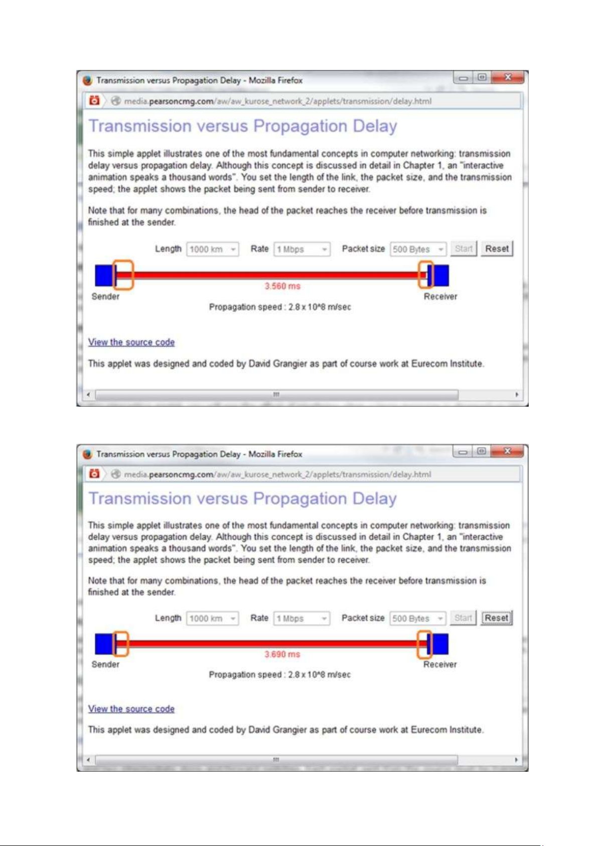
- The information is taken from Java Applet Transmission versus Propagation Delay
available in the text book resources of chapter 1.
The combination for which the sender finishes transmitting before the first bit of the
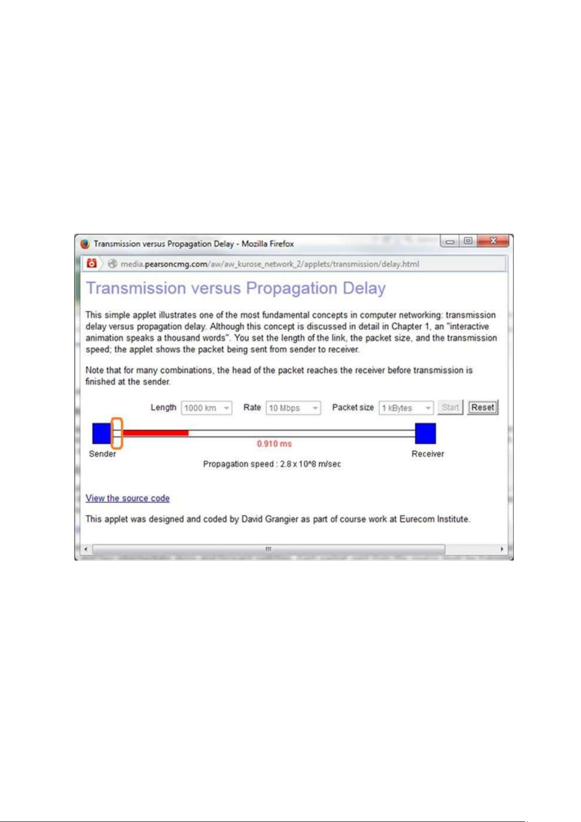
packet reaches the receiver is as shown below:
Length of the link (d) = 1000 km Packet size (L) = 1 kBytes lOMoAR cPSD| 58833082 •
Transmission rate(R) = 10 Mbps
Propagation speed (s) = 2,8*108 m/sec End-to-End delay = 3,620 ms
NOTE: orange color rectangles are used in the screen shots to highlight the main points.
The following screen-shots illustrates that the sender completed transmitting the first
packet before the receiver receives the first bit of the packet.
It can be observed from the screen shot that the first bit of the packet is not
reached the receiver but the sender has finished transmitting the first packet. lOMoAR cPSD| 58833082
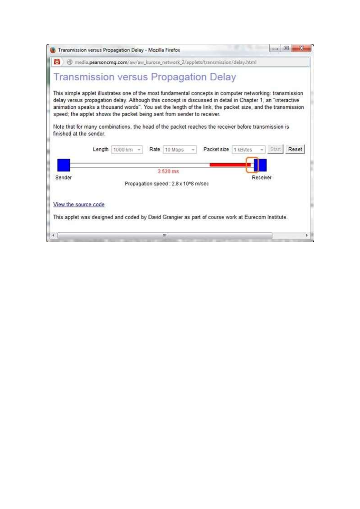
- The combination for which the first bit of the packet reaches the receiver before the
sender finishes transmitting: Length of the link (d) = 1000 km Packet size (L) = 500 Bytes
Transmission rate(R) = 1 Mbps
Propagation speed (s) = 2,8*108 m/sec End-to-End delay = 4,120 ms
It can be observed from the following screen shot that the first bit of the packet is about
to reach the receiver but the sender has not yet finished transmitting the first packet. lOMoAR cPSD| 58833082
- It can be observed from the following screen shot that the first bit of the packet reaches
the receiver but the sender has not yet finished transmitting the first packet. lOMoAR cPSD| 58833082
- It can be observed from the following screen shot that the first bit of the packet reaches
the receiver and the sender has finished transmitting the first packet. R18: - Consider the given data:
Length of the packet = 1000 bytes = 1000*8 bits = 8000 bits
Distance of the link = 2500 km = 2500*1000 m = 2500000 m
Propagation speed = 2,5*108 m/s Transmission rate = 2 Mbps
Calculate the time taken by a packet to propagate by using propagation time formula. Propagation time 10 msec
Therefore, the time taken for a packet of length 1,000 bytes to propagate over a link of
distance 2,500 km with propagation speed of 2,5*108 and transmission rate of 2 Mbps is 10 msec. - Consider the below data: Length of the packet = L Distance of the link = d Propagtion speed = s Transmision rate = R
Then, the time taken by a packet to propagate is given the propagation time. lOMoAR cPSD| 58833082 Propagation time
Therefore, the time taken for a packet of length L to propagate over a link of distance d
with propagation speed s and transmission rate R is .
- The propagation delay does not depend on the packet length. The propagation delay is
the time taken by the first bit of the data to transfer from one station to another. It
depends on the distance of the transmission link and the propagation speed.
- The propagation delay does not depend on the transmission rate. The propagation
delay is the time taken by the first bit of the data to transfer from one station to another.
It depends on the distance of the transmission link and the propagation speed. R19: a) Given data: R1 = 500 kbps R2 = 2 Mbps R3 = 1 Mbps
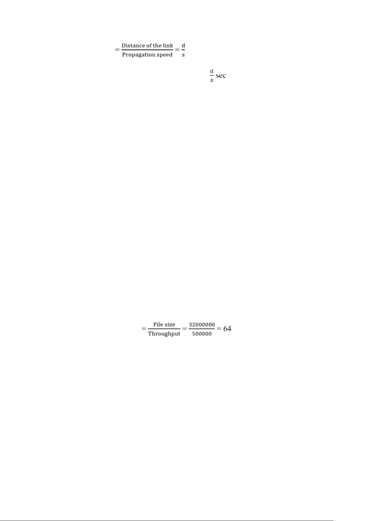
The throughput for the file transfer = Min {R1, R2, R3}
= Min {500 kbps, 2 Mbps, 1 Mbps} = 500 kbps
Hence, throughput for the file transfer is 500 kbps. b) File size = 4 million bytes = 4000000 bytes = 4000000*8 bits [1 byte = 8 bits] = 32000000 bits
Throughput for file transfer = 500 kbps
= 500*1000 bps [1 kbps = 1000 bits per second] = 500000 bps
Time taken to transfer the file seconds
Hence, the time taken to transfer the file is 64 seconds. c) Given data: R1 = 500 kbps R2 = 100 kbps R3 = 1 Mbps
The throughput for the file transfer = Min {R1, R2, R3}
= Min {500 kbps, 100 kbps, 1 Mbps} = 100 kbps
Hence, throughput for the file transfer is 100 kbps. File size = 4 million bytes = 4000000 bytes lOMoAR cPSD| 58833082 = 4000000*8 bits [1 byte = 8 bits] = 32000000 bits
Throughput for file transfer = 100 kbps
= 100*1000 bps [1 kbps = 1000 bits per second] = 100000 bps
Time taken to transfer the file = 320 seconds
Hence, the time taken to transfer the file is 320 seconds. R20:
When an end system A wants to send a large file to end system B, it first divides the
file into chunks. It then assigns a header to each chunk creating a packet. Each packet
contains the address of the destination in its header. Thus, multiple packets are generated from the file.
When a packet reaches the packet switch, the switch uses the destination address that
is in the header to know on to which link the packet has to be forwarded.
Each packet contains the address of the destination in its header. On reaching packet,
the address of the destination on the header of the packet specifies which outgoing link
it should be forwarded. This is analogous to asking which road to take. R21:
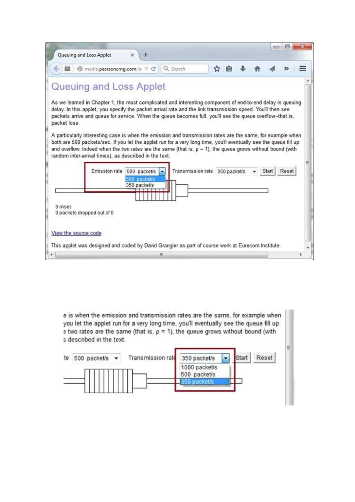
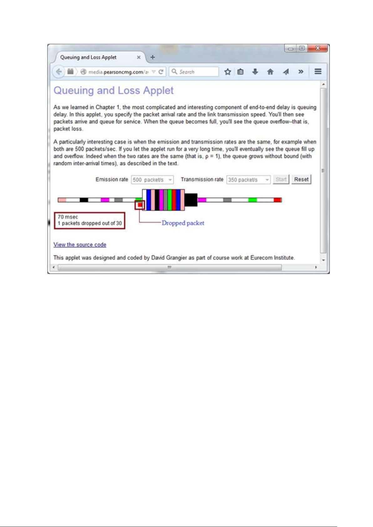
- The following is the screen-shot of Java applet available in the text book resources of chapter 1. lOMoAR cPSD| 58833082
In the screen-shot of the applet it can be observed that the dropdown list box of
"Emission rate" contains two values; 500 packets/s and 350 packets/s. The maximum among these values is 500.
Hence, the maximum emission rate is (λ) 500 packets/s.
Observe the above screen-shot (partial) that the dropdown list box of "Transmission
rate" contains three values; 1000 packets/s, 500 packets/s and 350 packets/s. The
minimum among these values is 350.
Hence, the transmission rate is (µ) 350 packets/s. lOMoAR cPSD| 58833082
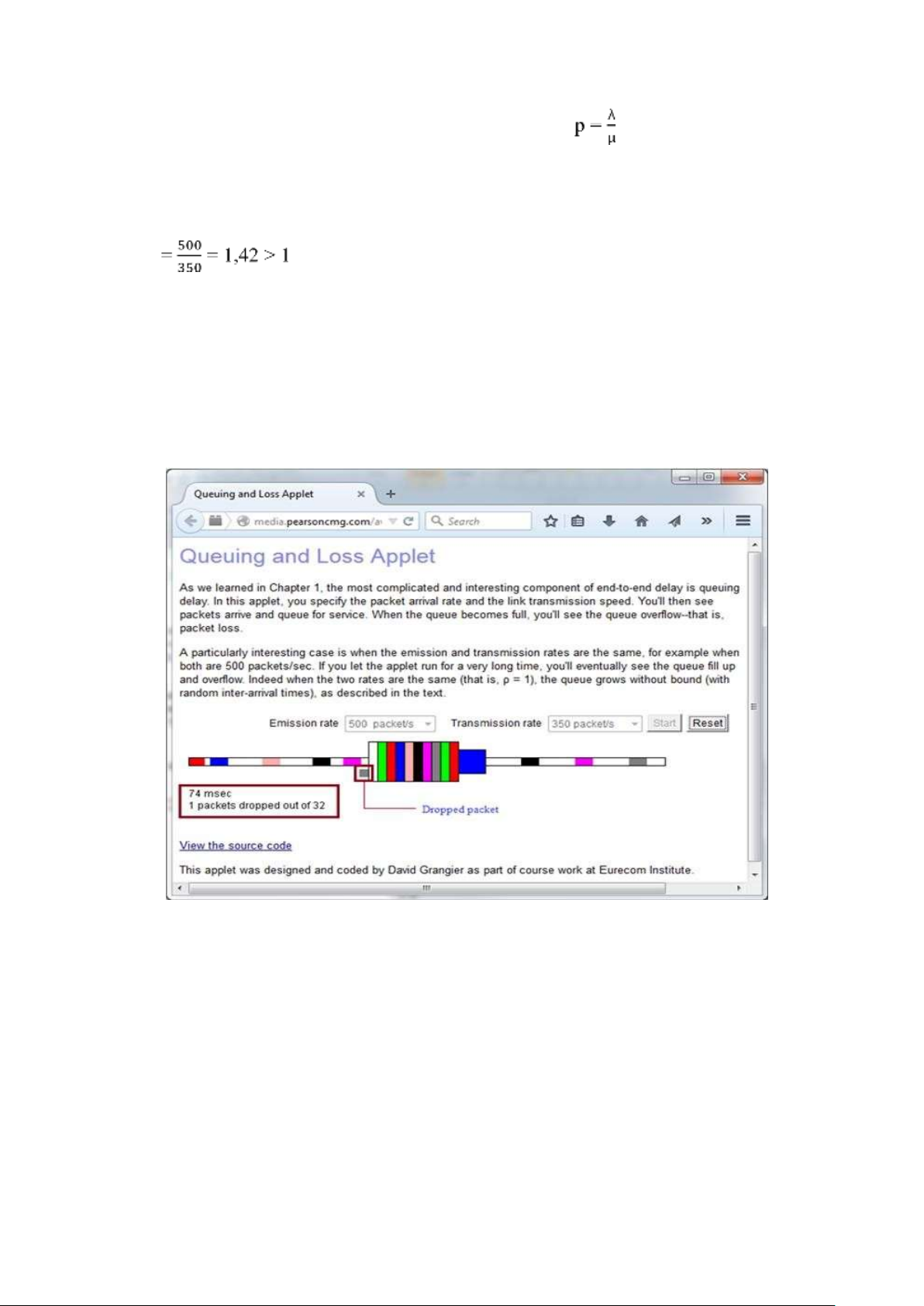
- Formula to calculate traffic intensity (p) is given below:
Calculate the traffic intensity when emission rate (λ) is 500 packets/s and transmission rate is (μ) 350 packets/s. p
Therefore, the traffic intensity when emission rate 500 packets/s and transmission rate350 packets/s is 1,42.
- Running the applet to observe packet loss:
Run the applet with emission rate 500 packets/s and transmission rate350 packets/s.
The following screen-shot shows the running applet at the instance where the packet is dropped.
The packet dropped (lost) and the time at that instance is highlighted in the screenshot.
It can be observed that the packet loss occurred at 74 msecs.
Again run the applet with emission rate 500 packets/s and transmission rate 350
packets/s. The following screen-shot shows the running applet at the instance where the
packet is dropped. The packet dropped (lost) and the time at that instance is highlighted in the screen-shot. lOMoAR cPSD| 58833082
It can be observed that the packet loss occurred at 70 msecs.
- In the first run, packet loss occurred at 74 msec and in the second run packet loss
occurred at 70 msec. Both the values are different.
The values are different because, the packet emission interval is not constant. SECTION 1.5 R22:
- The following is the list of five tasks that a layer can perform: 1.
Flow control: Managing the data flow between the two or more devices
(computers, nodes in a network etc.) to handle the data efficiently is known as flow control. 2.
Error control: Identifying and correcting the errors that occur in transmission of
data is known as error control. 3.
Segmentation and reassembly: The process of dividing the data to be transmitted
into small chunks for convenience to transfer the data is known as segmentation. Joining
the chunks to form the original data is known are reassembling. 4.
Multiplexing: The process of combining digital data streams in one signal over
a shared medium is known as multiplexing. lOMoAR cPSD| 58833082 5.
Connection setup: The process of establishing a connection between two devices
(computers, nodes in a network etc.) that are connected in a network is known as connection setup. -
Yes, it is possible that these one or more than one tasks can be performed by two or more than two layers. Example:
The flow control and error control tasks are performed by more than two layers. Flow
control task. The network layer and the transport layer perform the flow control task.
Error control task. The error control task is performed by session and transport layers
to detect the error. R23: -
The internet protocol stack consists of five layers. The following diagram shows the internet protocol stack: Application Transport Network Data Link Physical
1. Principal responsibilities of Application layer:
• Different applications related to network and corresponding application-layer
protocols reside in this layer.
• Some of the protocols that are present in this layer are HTTP, SMTP, and FTP. o
HTTP (HyperText Transfer Protocol) is used to transfer web documents. o
SMTP (Simple Mail Transfer Protocol) is used to exchange and transfer electronic mails. o
FTP (File Transfer Protocol) is used to transfer files from one node to other node in the network.
• The protocols of this layer are distributed over multiple end systems.
• The application in the system of one end will exchange the packets of
information with the application present in the system at the other end.
2. Principal responsibilities of Transport Layer:
• The main responsibility of transport layer is to transport the messages of
application-layer between two endpoints.
• The main protocols used to transport the messages are TCP and UDP.
• The TCP (Transmission Control Protocol) is a connection-oriented service
provider. This protocol guarantees the delivery of messages. It also provides flow control
• The UDP (User Datagram Protocol) is connection less service provider. It
doesn't provide flow control or congestion control. lOMoAR cPSD| 58833082 3. Network Layer:
• The main responsibility of the network layer is to move the packets of data
(known as datagrams) between any two hosts in the network.
• The service provided by this layer is similar to the postal service. It moves the
datagrams and delivers them based on the destination address.
• The protocol in this layer is IP (Internet Protocol) protocol which defines the
fields of the datagram. Based on the address field, the datagrams are delivered. 4. Datalink Layer:
• The main responsibility of datalink layer is to move the packets from one node
(here node may be a router, a host or any other network device) to the next node through an optimal route.
• Network layer relays on this layer for datagram delivery.
• The protocols like PPP (Point-to-Point Protocol) are employed in this layer for finding the optimal route.
• The protocols in this layer are dependent on the specific link that is employed for moving the data packet. 5. Physical Layer:
• The main responsibility of physical layer is to move the individual bits within
the frame from one node (here node may be a router, a host or any other network
device) to the next node through physical transmission media.
• The protocols in this layer are dependent on the specific link that is employed for moving the data packet.
• Different physical media require different protocols. The protocol to transfer
the bits using twisted-pair is different from the protocol used in coaxial cable.
The bit is moved in different ways across the links based on the media used. R24:
- Application - Layer messages:
The packet of information exchanged between an application at one end and an
application at the other end in the system is known as message.
The application layer protocol is distributed over the multiple end system. The
messages are transferred between the applications in the systems. - Transport - Layer segments:
The data packet which is made up of application-layer's message is transferred between
the endpoints is known as segment.
The protocols of transport layer TCP (Transmission Control Protocol) will
break the application layer's messages into small segments to provide congestion- control mechanism. - Network - Layer datagram: lOMoAR cPSD| 58833082
- Transport layer gives the destination address and the segment to the network layer.
The network layer combines the segment and address to form a data packet known as datagram.
- Network layer moves this datagram from source node to the destination node based
on the address. Datagrams are independent packets of the connectionless network structure. - Link - Layer Frame:
The datagram of the network layer is handover to the link layer at each node. The link
layer delivers the datagram to the next node along with its route. The datagram along
with its route is known as frame.
Network layer relays on the link layer for transfer of frames (packets) from one node to the next node. R25:
- The following are the layers in the internet protocol stack that the routers process: 1.
Physical Layer: Router is a physical device and acts as a bridge between
computer and the network. So, the router directly processes the physical layer. 2.
Data Link Layer: Router sends the frame to the next node (routers, systems and
other devices) after identifying the route that the packet needs to travel. So, the router
processes the data link layer. 3.
Network Layer: Router assigns address to the segment which it receives and
forms a datagram. So, the router processes the network layer.
Therefore, routers process the physical, data link, and network layers of the internet protocol stack.
- The following are the layers in the internet protocol stack that the link-layer switch process: 1.
Physical Layer: Link layer switch is a physical device and acts as a bridge
between computer and the network. So, the switch directly processes the physical layer. 2.
Data Link Layer: Link layer switch floods the frame to all nodes (routers,
systems and other devices) that are connected to it. So, the switch processes the data link layer.
Note: Switches doesn't have capability to assign address.
Therefore, link-layer switches process the physical and data link layers of the internet protocol stack.
- The following are the layers in the internet protocol stack that the host process: 1. Physical layer 2. Data Link layer 3. Network layer 4. Transport layer 5. Application layer lOMoAR cPSD| 58833082
Host systems are the devices at the user end with high hardware capabilities. Personal
computers, servers are examples of hosts. They are capable of processing all the layers.
Therefore, host process all the 5 layers of the internet protocol stack. SECTION 1.6 R26:
- Difference between Virus and Worm: Virus Worm
Virus is a kind of malicious software
Worm is a kind of malicious software
It requires human intervention to spread It doesn't require human intervention to spread
Viruses are generally attached to the Worms are self-executable programs.
executable files. When the user executes Once they enter into a computer, it starts
the infected file, virus starts spreading harming the computer and harms the computer
Viruses spread by sharing infected files, as Worms spread through vulnerable attachments to the e-mails
processes. They scan the host IP
addresses and port numbers. Checks for
the vulnerable processes to infect. Using
the vulnerability, they spread from one computer to the other
C-Brain and Macmag are examples of
Bagle and Sober are examples of worms viruses
- Malicious software: The software that are intended to perform undesired operations
against the legitimate computer user such as disrupting computer operation, gathering
sensitive information, or gaining access to personal information are known as
malicious software or simply Malware. R27: - Process to create a botnet:
• The attacker who wants to create a botnet keeps on monitoring host systems to
identify the vulnerability in it.
• Once the vulnerability (like buffer overflow in an application) is identified, attacker tries to exploit it.
• After identifying the vulnerability, attacker scans a series of host systems to
find the hosts having similar vulnerability.
• Attacker uses a Trojan to compromises the host system.
• Using this compromised host system which contains the Trojan, the remaining
systems with similar vulnerability are attacked and make them compromised.
• The network of these compromised host systems forms the botnet. - Using
botnet for DDOS (Distributed Denial-of-Service) attacks:
Tài liệu liên quan:
-
Bài Tập Lớn Mạng Máy Tính - Xây Dựng Hệ Thống Mạng CMC (DCCNTT13.10.18). Môn Mạng máy tính (ĐHCN) | Trường Đại học Công nghệ, Đại học Quốc gia Hà Nội.
109 55 -
Hệ Thống Phát Hiện Phương Tiện Giao Thông Bằng YOLOv3. Môn Mạng máy tính (ĐHCN) | Trường Đại học Công nghệ, Đại học Quốc gia Hà Nội.
106 53 -
Mạng máy tính - Bài tập chương 2: Câu hỏi ôn tập và giải thích.
111 56 -
Lab 13 - AWS EBS Overview and Management Techniques. Môn Mạng máy tính (ĐHCN) | Trường Đại học Công nghệ, Đại học Quốc gia Hà Nội.
103 52