MLR-Electricity & Circuits eBook: Class Overview & Safety Guidelines môn Kỹ thuật điện | Trường Đại Học Thái Nguyên
Always follow all general safety guidelines for servicing motor vehicles with regard to electrical connections, flammable or corrosive materials, adequate ventilation, jacking and supporting, working around hot or moving parts, proper use of parking brakes, gear selectors, wheel blocks, and disabling fuel or ignition systems. Tài liệu giúp bạn tham khảo, ôn tập và đạt kết quả cao. Mời bạn đọc đón xem!
Môn: Kỹ thuật điện 13 tài liệu
Trường: Đại học Thái Nguyên 385 tài liệu
Tác giả:


Preview text:
lOMoAR cPSD| 45740413 Maintenance and Light Repair: Electrical
A Today’s Class© Course eBoo k © 2016 Melior, Inc. lOMoAR cPSD| 45740413 Table of Contents
Unit 1: Introduction To Electricity ......................................................... 4
Overview ................................................................................................ 4
Safety ................................................................................................................... 4
Electricity ............................................................................................................. 5
Electrical Circuits ................................................................................................. 9
Protection Devices ............................................................................................. 10
Control Devices .................................................................................................. 14
Symbols ............................................................................................................. 16
Electrical Properties .............................................................................18
Voltage ............................................................................................................... 18
Current .............................................................................................................. 20
Resistance .......................................................................................................... 21
General Rules .................................................................................................... 22
Voltage Drop ...................................................................................................... 23
Digital Multimeters ..............................................................................24 Introduction
....................................................................................................... 24
Digital Multimeters ............................................................................................ 25
Scaling ............................................................................................................... 26
Measurements .................................................................................................. 30
Converting Values .............................................................................................. 33
Unit 2: Electrical Circuits And Devices .................................................37
Series Circuits ....................................................................................... 37 Introduction
....................................................................................................... 37
Circuit Elements................................................................................................. 37
Voltage Drop ...................................................................................................... 39
Series Circuits .................................................................................................... 42
Unit 3: Electrical Relationships And Equations .....................................44
Ohm's Law ............................................................................................ 44
Ohm's Law ......................................................................................................... 44
Relationships and Formulas ............................................................................... 45 lOMoAR cPSD| 45740413
Calculations for Circuits ..................................................................................... 47
Unit 4: ADVANCED ELECTRICAL CIRCUITS ............................................49
Parallel Circuits ..................................................................................... 49
Parallel Circuits .................................................................................................. 49
Ohm’s Law for Parallel Circuits .......................................................................... 55
Series-Parallel Circuits ....................................................................................... 56
Unit 5: Electrical Diagnosis And Wire Repair ........................................58
Electrical Diagnosis ...............................................................................58
Circuit Faults ...................................................................................................... 58
Test Lights .......................................................................................................... 63
Headlight Circuits .............................................................................................. 65
Wiring Diagrams ................................................................................................ 67
Wire and Wire Repair ...........................................................................70
Wire Applications .............................................................................................. 70
Stripping ............................................................................................................ 70
Splicing .............................................................................................................. 71
Terminals ........................................................................................................... 74
UNIT 1: INTRODUCTION TO ELECTRICITY
The following topics are addressed in this unit: Overview • Safety • What is Electricity? • Electrical Circuits • Protection Devices • Control Devices • Symbols Electrical Properties • Voltage • Current • Resistance
• General Rules of Electricity • Voltage Drop • Digital Multimeters • Introduction Digital Multimeters • Introduction • Digital Multimeters lOMoAR cPSD| 45740413 • Scaling • Measurements • Converting Values Overview
In this unit, we take a look at the fundamentals of electricity. Safety
Safety Warnings and Cautions
Safety in the workplace is of great concern to all of us. Especially since the concepts learned in
each module of this training program will be applied using real test equipment, on live electrical circuits.
It is, therefore, imperative that students understand how extremely important electrical safety
is. The words “caution”, “warning”, and “danger” will appear throughout this material and must
always be heeded. If you do not heed the safety message, you can not only damage components
and equipment, you can injure or kill yourself or someone else.
Every year, people are injured or killed and property is damaged as a result of not following
electrical safety rules and common sense. Pay attention and use safe practices.
WARNING! To avoid possible personal injury:
• Always follow all general safety guidelines for servicing motor vehicles with regard to
electrical connections, flammable or corrosive materials, adequate ventilation, jacking and
supporting, working around hot or moving parts, proper use of parking brakes, gear
selectors, wheel blocks, and disabling fuel or ignition systems. Refer to the equipment
user's manual and vehicle service manual for the operation you are performing.
• When making electrical measurements, never exceed the voltage or current limits for the equipment.
• Use extreme caution when working with circuits that have greater than 60 volts DC or 24 volts AC.
• Do not operate damaged equipment.
• Automotive batteries can explode, and have enough power to arc weld. Always respect
the power of a battery, even a dead battery. Always wear approved safety glasses when
working around batteries. The use of rubber gloves is recommended when working with electrolytes.
• The ground terminal of a battery should always be disconnected first and reconnected last.
• Connect battery chargers to a battery before plugging in the charger.
• When jump-starting a vehicle, always follow the proper procedure. Do not connect the
jumper cable to the negative battery terminal of the vehicle you are jump-starting.
• Accidentally shorting the positive battery terminal, or system voltage, to ground with a
tool or metal object can cause severe burns. Jewelry should be removed before working with electrical systems. lOMoAR cPSD| 45740413
Know the locations of fire extinguishers, eyewash stations, and first aid kits. First aid kits should
always contain a bottle of sterile, acid-neutralizing eyewash. This is especially important near the
battery storage and service area. Electricity What is Electricity?
In order to properly diagnose and repair automotive electrical systems, a technician must first
have an understanding of how those systems operate. In this section, we will look at electrical
fundamentals and how they determine the construction and application of automotive circuits. What is electricity?
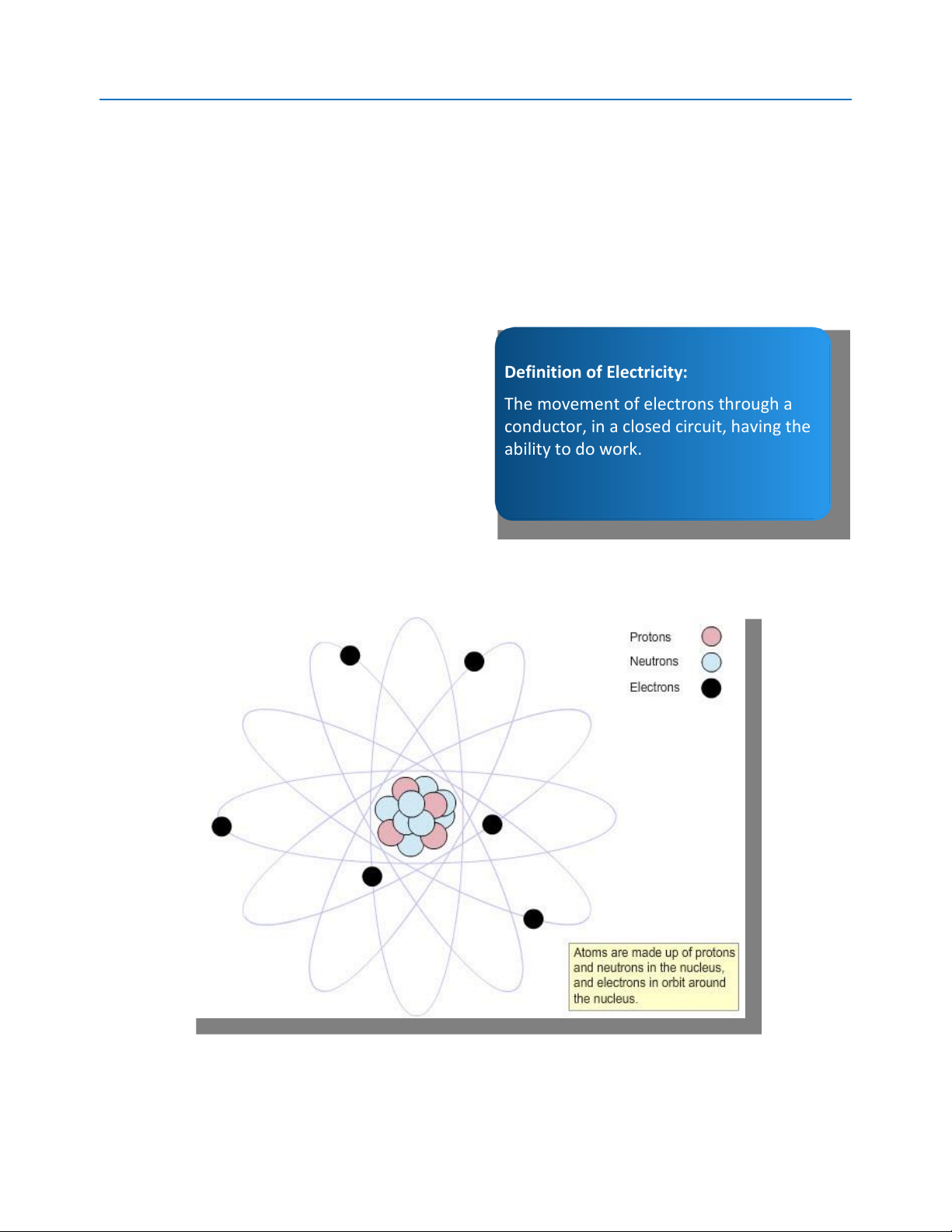
Electricity can be described in a number of ways,
Definition of Electricity:
but for our purposes it is defined as the
The movement of electrons through a
movement of electrons through a conductor, in
conductor, in a closed circuit, having the
a closed circuit, having the ability to do work. ability to do work. Atoms
Remember from science class that atoms are
composed of a nucleus, containing protons
(which have a positive charge) and neutrons (which have no charge), with electrons revolving
around it (which have a negative charge). Atom
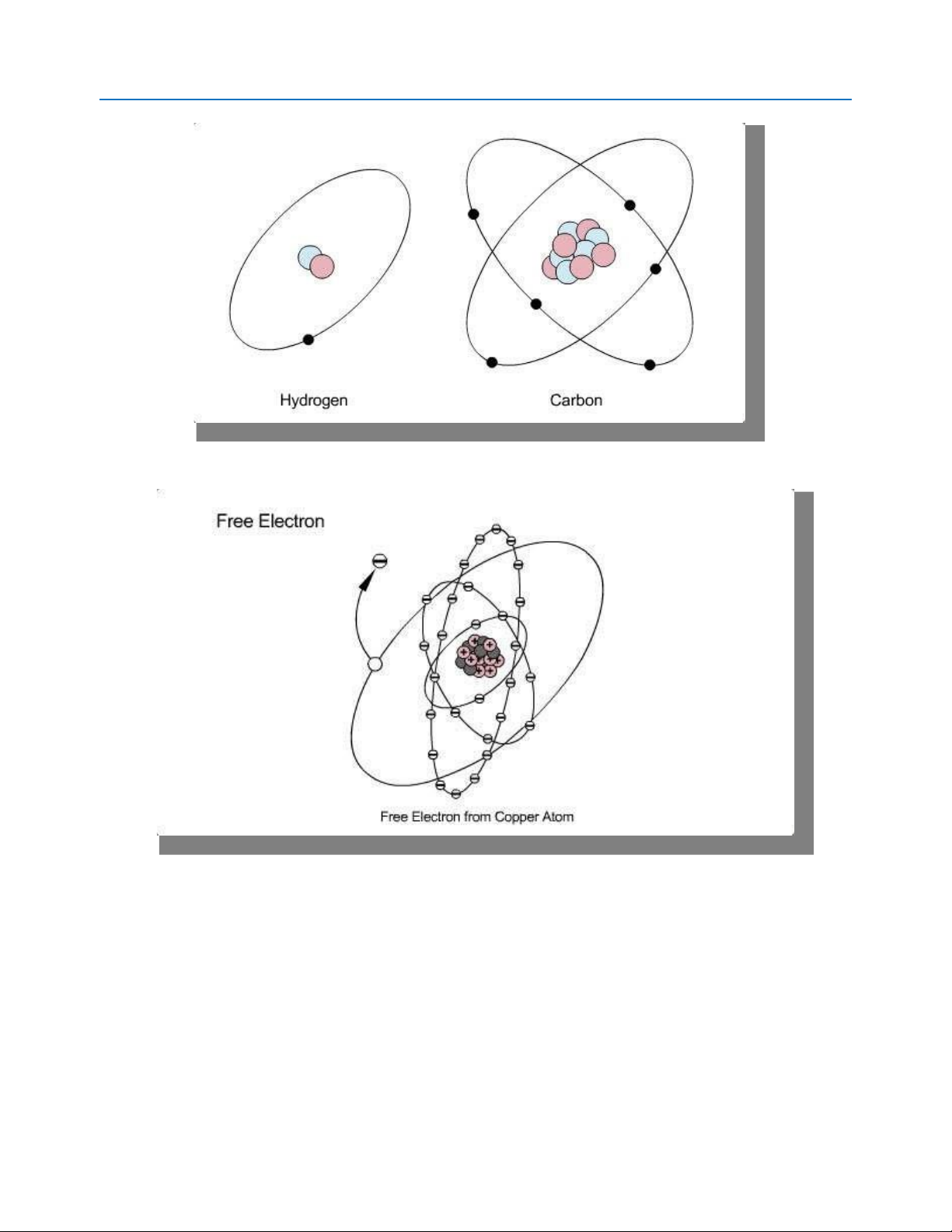
Recall also that each type of atom has a different number of protons and neutrons in the nucleus,
as well as electrons around its perimeter, than other types of atoms. For example, hydrogen has
one electron while carbon has six. lOMoAR cPSD| 45740413
Atomic Structures of Hydrogen and Carbon
Let's look at one specific example of an atom -- copper. Atomic Structure of Copper
A copper atom has 29 electrons arranged in different layers, or shells, around the nucleus; two
in the first shell, eight in the second shell and 18 in the third shell, for a total of 28. That leaves
just one free electron in the outer shell, or valence shell, of the atom. That free electron is also
referred to as a valence electron. lOMoAR cPSD| 45740413
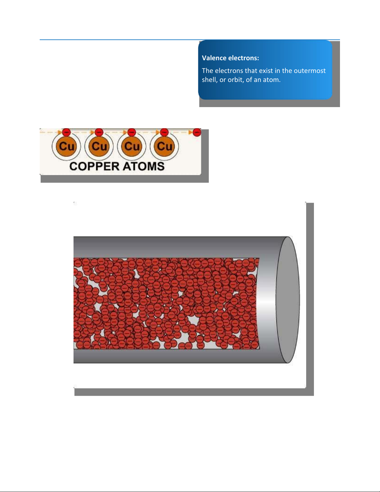
When a sufÏcient electrical force (voltage) is
applied to an atom, the one free electron in the Valence electrons:
outer shell is pushed out of its orbit. It will then
begin to carry its negative charge down a wire
The electrons that exist in the outermost
(conductor), much like feeding ping pong balls shell, or orbit, of an atom. through a paper towel roll.
Electrons being displaced from atoms
The greater the applied force (voltage), the more electrons will be moved. Electrons in a conductor
The movement of those electrons is what makes up electricity, and is what operates the lights,
horns, computers, and every other electrical device on a car or truck. lOMoAR cPSD| 45740413
Conductors, Insulators, and Semiconductors
Atoms that have one or two electrons in the valence shell are called conductors because they
move electrons well. These conductors include copper, gold, silver, aluminum, nickel, zinc, and
others. That is why those substances are used to make wire.
Atoms with a large number of electrons in the
outer shell (six to eight) are called insulators Atom info:
because they don't release electrons easily.
Materials that make good insulators include
1 or 2 valence electrons are conductors rubber and plastics.
3 , 4, or 5 valence electrons are
The remaining atoms that have around four semiconductors
electrons in the valence shell (three to five) are
6 , 7, or 8 valence electrons are insulators
called semiconductors because they are neither
good conductors nor good insulators.
Semiconductors are used, however, to make
electronic components such as diodes and transistors. Electrical Circuits
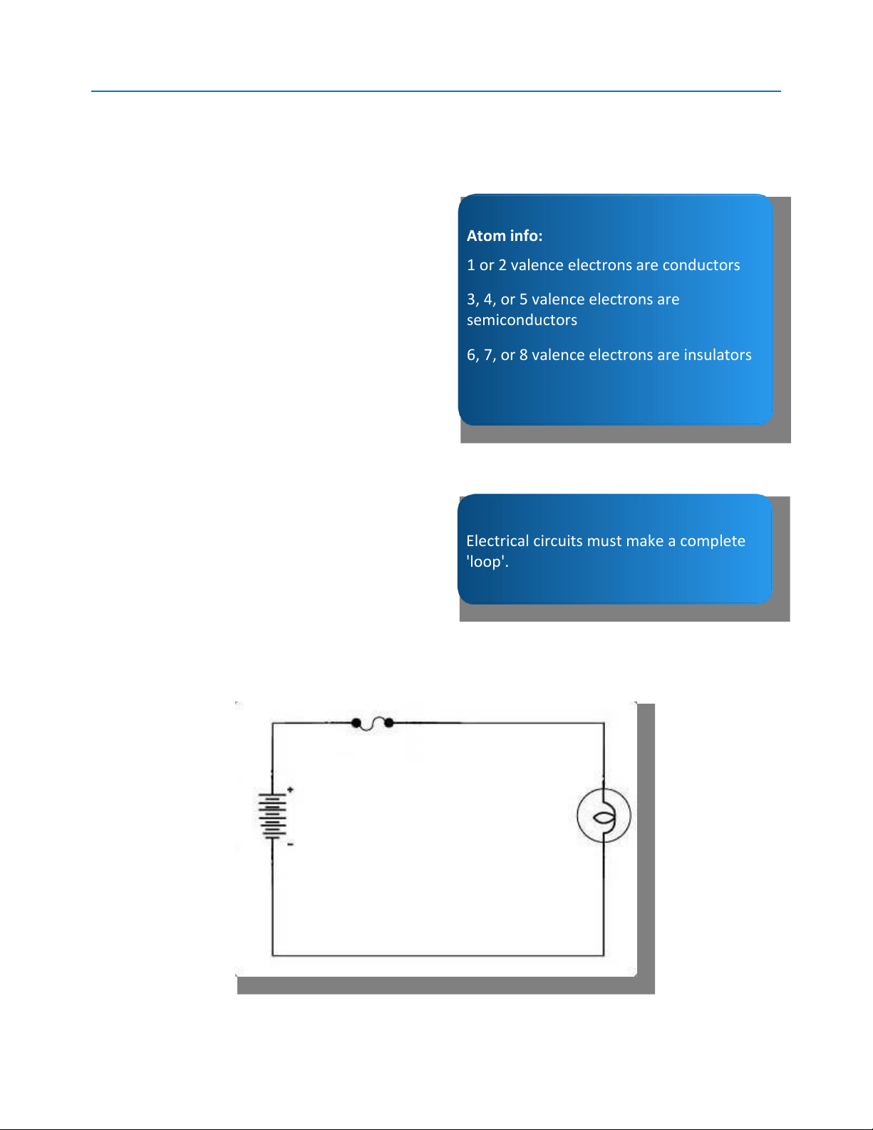
Recall from the definition that a closed circuit is
needed to turn electricity (electron flow) into
work. But what, exactly, is a circuit?
Electrical circuits must make a complete 'loop'.
For electrical applications, a circuit is a complete
'loop' that carries electrons from a power or
energy source -- such as a battery or generator --
through one or more conductors, such as wires, through one or more loads, to transform that
electron flow into useful work. Circuit lOMoAR cPSD| 45740413
All circuits must start at the power source and, after moving through all of the conductors and
loads, return to that same power source. In addition, most circuits also contain some form of
control device, such as a switch, to turn the circuit ON or OFF, and a protection component (a
fuse or circuit breaker) to protect the circuit against damage. Circuit Components
All circuits, regardless of how complex they are, contain the same six types of components. These components include:
1. A power source, such as a battery or generator
2. Protection devices, such as fuses or circuit breakers, to prevent damage to the circuit
3. Control devices, such as switches, to manage the electron flow
4. Loads (lights, motors, etc.) that turn the electron flow into work
5. Conductors to carry the electrons
6. Ground, such as the battery negative terminal or the ‘-’ connection on a power supply, for completing the circuit loop
Each of these will be covered in greater detail in later sections.
Note: Going forward, we will be using electrical circuit diagrams like the one shown above.
Diagrams such as this one are known as schematics. Protection Devices
One of the characteristics of electrical circuits is
that the more electrons that flow through a Circuit Protectors
conductor, the greater the heat that will be
created. As a result, protection devices are used
Circuit protectors are used to prevent
in circuits to prevent damage from excessive
wiring damage from excessive current. electron flow.
Automotive circuit protectors come in three
primary forms: fuses, circuit breakers (automatic
and manual reset), and fusible links. While fuses and circuit breakers are still commonly used in
automotive applications, fusible links are not (although we will cover them here).
All three varieties are designed to perform the same function, which is to open a circuit (like
turning a switch OFF) if there is too much electron flow, before the circuit wiring can be damaged.
There are two things to keep in mind concerning fuses and circuit breakers:
• They are designed to protect the circuit wiring, but not necessarily any other components.
• It is the HEAT from electron flow that causes these devices to open, not the electron flow itself. lOMoAR cPSD| 45740413 Fuses
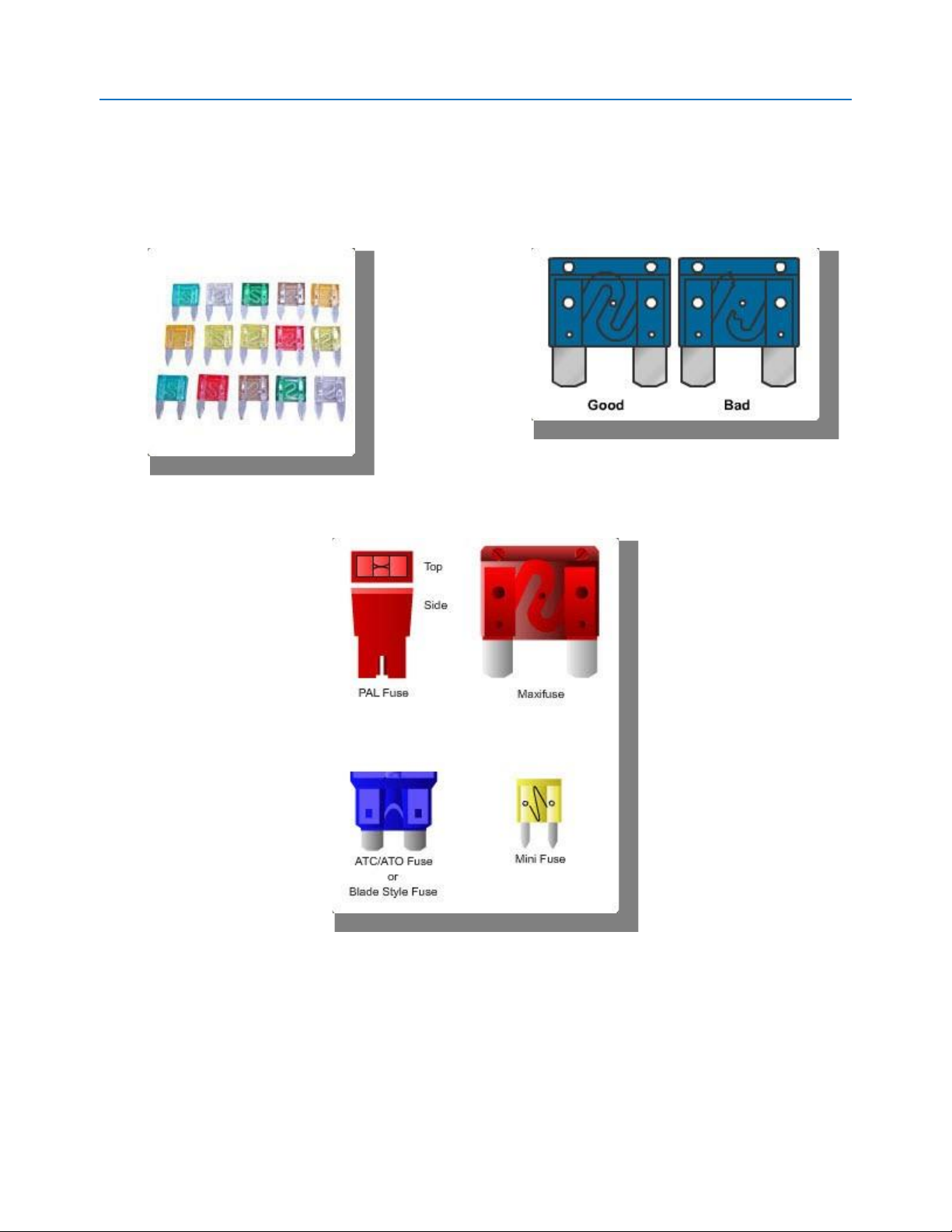
The most common type of protection device is the fuse. A fuse has a thin metal strip either inside
a glass cylinder or in a plastic holder. The metal strip is designed to melt and open the circuit if
too many electrons pass through the fuse. A fuse that has blown cannot be repaired and must be replaced. Typical Fuses Good/Bad Fuses Assorted Automotive Fuses lOMoAR cPSD| 45740413
Automotive fuses typically come in three sizes -- small (minifuses), medium (autofuses), and large
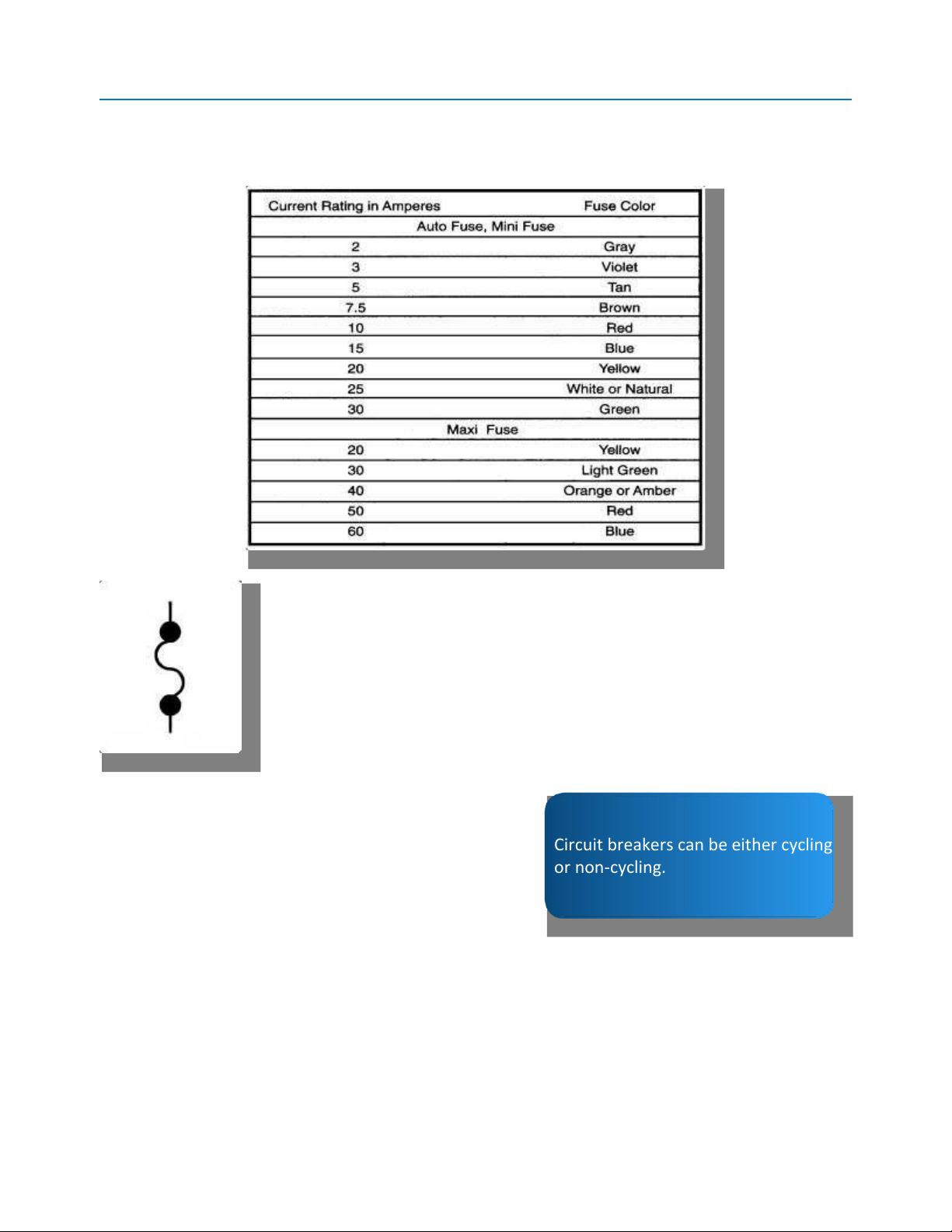
(maxifuses) -- and are rated in amps (the measurement of electron flow). They are also
Automotive Fuse Amp/Color Code Chart Fuse Symbol
CAUTION : Never replace a fuse with one of a higher amps rating. Serious
circuit damage or electrical fire could result!
Automotive electrical fuses, regardless of their rating, will be indicated on
electrical schematics with the symbol to the left. Circuit Breakers
A circuit breaker, like a fuse, is a protection device
Circuit breakers can be either cycling or non-cycling.
colorcoded and labeled (see chart below) to indicate the maximum amps they are rated to
handle. designed to open when the electron flow exceeds a calibrated amperage.
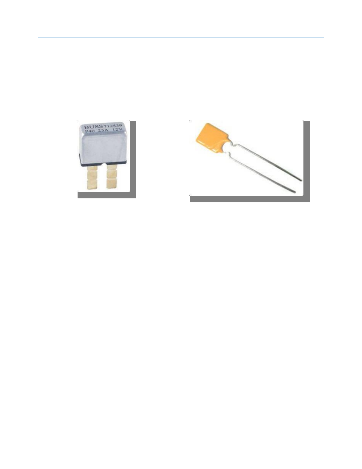
An electromechanical circuit breaker contains a
bimetal strip made of two different metals
bonded together. When excess heat is applied,
the metal strip will separate, opening the
circuit and preventing electron flow. Some lOMoAR cPSD| 45740413
circuit breakers must be reset manually while
others reset automatically; these are referred
to as 'cycling' circuit breakers.
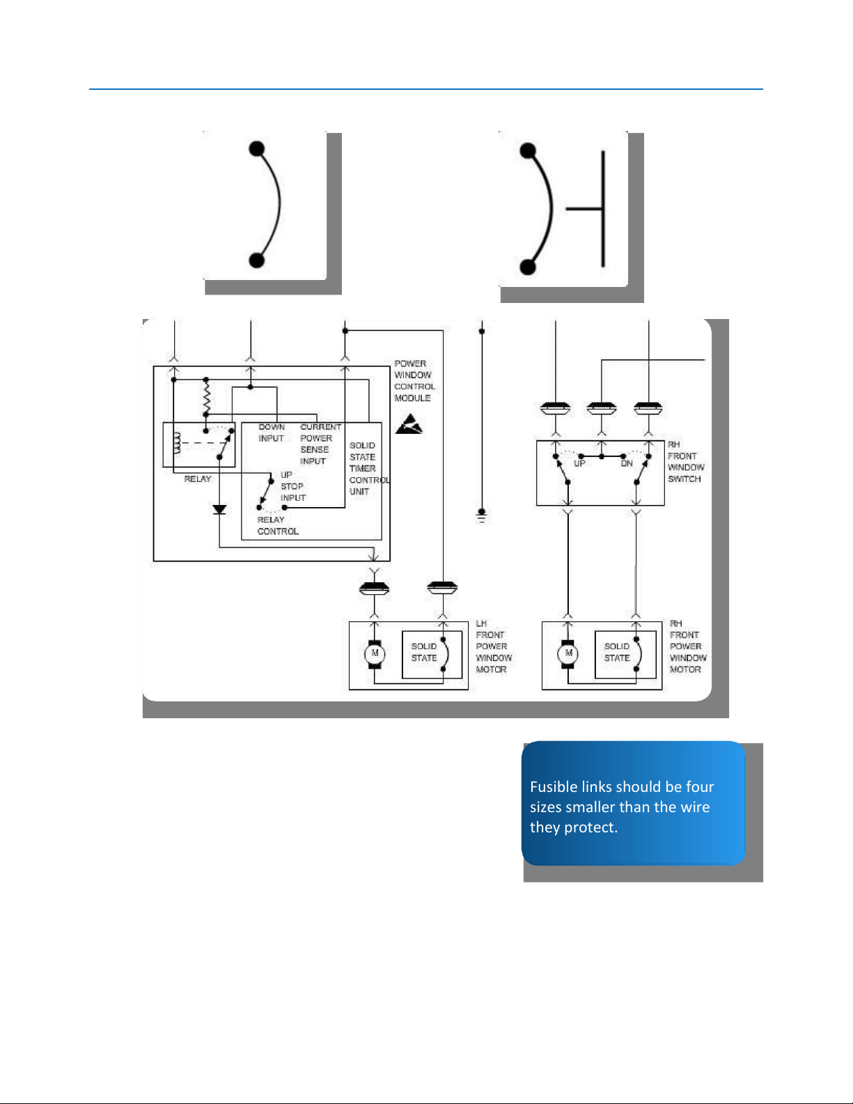
An electronic circuit breaker, also called a PTC, will open automatically when the rated amperage
is exceeded, and close again when the amperage is reduced. Electronic circuit breakers are
typically used to protect power window circuits, and other similar circuits, if a switch becomes stuck and does not turn off. Mechanical Circuit Breaker
Electronic Circuit Breaker (PTC)
Automotive circuit breakers, regardless of their rating, will be indicated on electrical schematics with the two symbols below. lOMoAR cPSD| 45740413 Self-ResetÝng Circuit Manually-ResetÝng Breaker Symbol Circuit Breaker Symbol
Power Window Schematic with PTCs Fusible Links
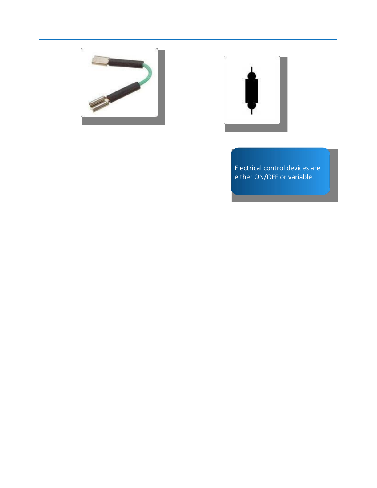
Another type of electrical protection device is the fusible link
wire. A fusible link is a section of wire that is typically four
wire-gauge sizes smaller than the conductors of the circuit it Fusible links should be four sizes smaller than the wire
protects. Because they are smaller than the rest of the they protect.
circuit wire, they will melt first, in the case of excessive
electron flow, and prevent other damage to the circuit.
Fusible links also have a special insulation coating that
resists melting when it overheats.
Although fusible links are no longer as common as either fuses or circuit breakers, there are still
many of them currently in use, mostly in circuits rated at 30 amps or higher. lOMoAR cPSD| 45740413 CAUTION: Fusible Link A blown fusible Fusible Link link cannot be Symbol repaired and must be replaced. Never attempt to replace fusible link wire with regular electrical wire! Automotive fusible links,
regardless of their rating, will be indicated on electrical
schematics with the symbol below. Control Devices
Electrical control devices are
Control devices in electrical circuits are used either for the either ON/OFF or variable.
purpose of starting or stopping electron flow, or to limit
the electron flow. Those that turn the electron flow ON or
OFF are called switches, while those that limit electron
flow are variable resistors. For now, we will limit ourselves to switches. Switches
Electrical switches are used to control current flow in an electrical circuit. Switches come in
different shapes and sizes and can be controlled either manually or by hydraulic pressure, heat, vacuum or even light.
An electrical switch can be either normally-open or normally-closed, depending on the type of
circuit it is controlling. A normally-open switch does not pass electrons when it is OFF but does
pass electrons when it is ON. A normally-closed switch has contact (passes electrons) when it is OFF but not when it is ON.
When replacing an electrical switch, make sure you are using one that can handle the electrical load.
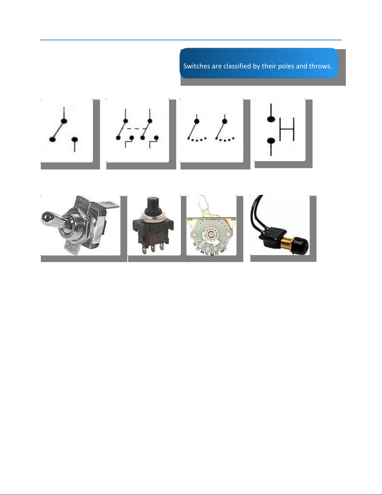
Switches are classified by the number of 'poles' and the number of 'throws' they have. For
instance, a single-pole switch controls only one circuit, while a double-pole can control two
circuits, and so on. Likewise, the 'throws' are the number of ON/OFF positions a switch has. As
such, a single-throw switch has one ON and one OFF position, a double-throw has two (ON-
OFFON), and so on. Common types of switches include the single-pole single-throw (SPST), the
singlepole double-throw (SPDT), the double-pole double-throw (DPDT), and on to multiple poles and multiple throws.
One additional type of switch is the momentary switch, which is spring-loaded and has
contact only as long as it is held closed. Horn switches and brake light switches are examples of momentary types. lOMoAR cPSD| 45740413
Electrical Switch Symbols
The symbols and pictures shown here
are common with most manufacturers.
Switches are classified by their poles and throws. Single Pole Double Pole Multiple Pole Momentary Single Throw Single Throw Multiple Throw Actual Switches Single Pole Single Pole Multiple Pole Momentary Single Throw Double Throw Multiple Throw
Switches can be used on either the positive side of a circuit or on the negative side of a circuit. Symbols
A diagram that is used to show the components and configuration of an electrical circuit is called
a schematic. Instead of pictures showing a circuit's parts, schematics use symbols. Technicians
and students must learn to read and recognize electrical symbols in order to understand and repair electrical circuits.
Listed below are a few of the most common electrical symbols. Some have appeared before and
some have not, but all of them will be used during electrical training. If desired, this page can be
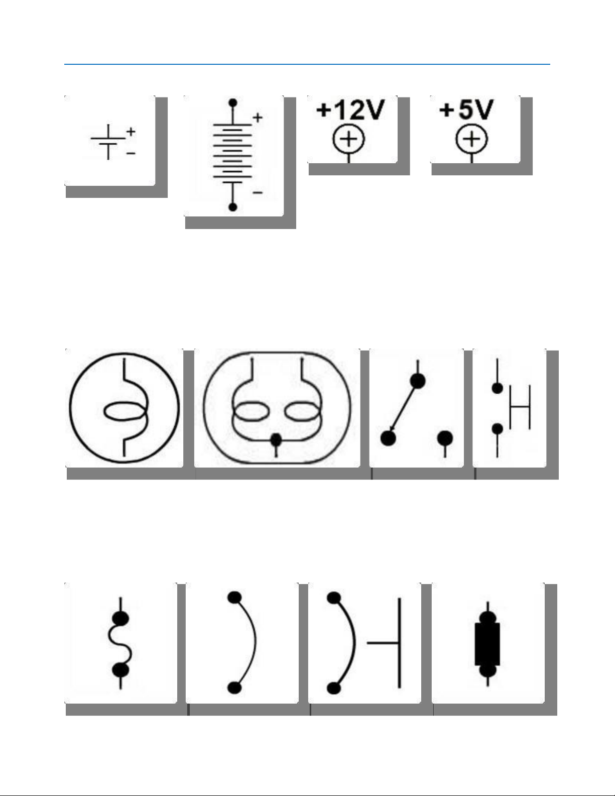
printed out and saved for future reference. lOMoAR cPSD| 45740413 Battery Cell Battery Power Supply- Power Supply- 12 Volts 5 Volts
• Battery cell - This symbol indicates a two-volt battery cell. The longer line is the positive side
and the shorter line is the negative side.
• Battery - Six of the two-volt cells are combined to form this automotive battery.
• Power supply - The 12-volts indicated here is from either a power supply or a charging system rather than a battery.
• Power supply - Same as above except it is 5-volts instead of 12. Single Filament Dual Filament Switch Momentary Bulb Bulb Switch
• Bulb - This could be any bulb with a single filament.
• Bulb - The bulb shown here will have two filaments.
• Switch - This is a toggle-type device with ON or OFF positions.
• Momentary switch - A switch like this closes a circuit only as long as it is pressed. Fuse Circuit Breaker- Circuit Breaker- Fusible Link Automatic Manual lOMoAR cPSD| 45740413
• Fuse - One-time-use protection device.
• Circuit breaker - This device will automatically reset after a circuit failure.
• Circuit breaker - Same as prior device except it must be manually reset.
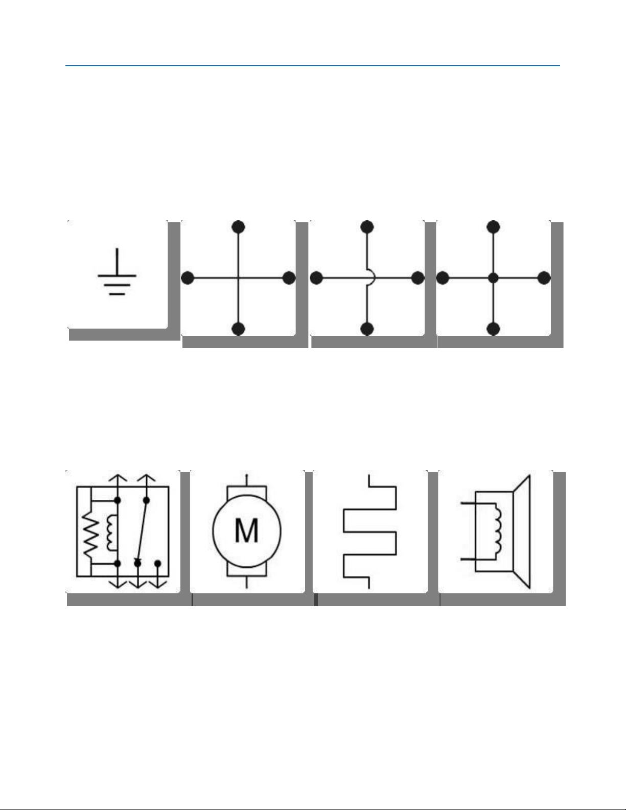
• Fusible link - Wire-type protection device. Ground Two Circuit Two Circuit Wires - Two Circuit Wires - Wires Unconnected Connected
• Ground - This symbol shows a connection back to the negative side of a circuit.
• Two circuit wires - This symbol may or may not show connected wires. If it used to indicate
connected wires, then the next symbol indicates non-connected wires. If it is used to show
non-connected then the last symbol, with the dot in the middle, will show connected wires.
• Two circuit wires (unconnected) - These wires are not connected.
• Two circuit wires (connected) - These wires are connected to each other. Relay Electric Motor Electric Heating Horn or Speaker Element
• Relay - This is an electromagnetic switch.
• Electric motor - Only one symbol is used for motors, regardless of their size or use.
• Electric heating element - This item is the same for rear window defoggers, seat heaters, cigarette lighters, etc.
• Horns or speakers - Any device whose purpose is to project sound. lOMoAR cPSD| 45740413 Electrical Properties
In this section, we will cover the four basic electrical entities: voltage, current, resistance, and power. Voltage
Voltage is the component of electricity that is best
described as the pushing force or electrical pressure
which causes electrons to move through a conductor.
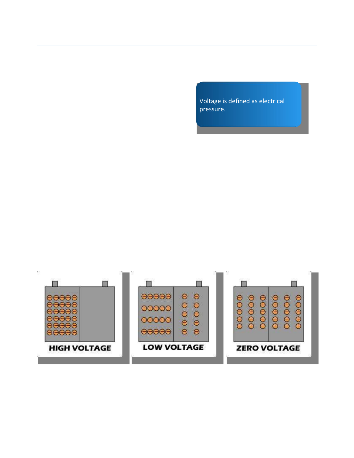
Voltage is defined as electrical pressure.
Voltage is often compared to the water pressure in a
garden hose that pushes water out of a nozzle. Even
if the nozzle on the hose is closed, there is still water
pressure in the hose, even though no water is flowing.
Electrical circuits work the same way in that there can be voltage present in a circuit, even if no
electrons are moving. However, it is important to remember that if there is no voltage in a circuit
(no pushing force), no electrons will move.
But, where does voltage come from? To understand that we need to recall our earlier discussion
about free electrons. While electrical work is done by electrons moving through a conductor,
before anything can move there must first be some electrons to start with. In automotive
applications that place is typically the battery.
In a battery, if there are more free electrons on one side than on the other side (between the
positive and negative plates), there is said to be a 'difference of potential,' or voltage. The greater
the difference between the number of electrons on one battery plate and the number on the
other plate, the higher the voltage. As the number of electrons on one plate approaches the
number on the other plate, the lower the voltage becomes. A dead battery is one that has the
same number of electrons on the positive plates as on the negative plates.
As we work with electricity, we will see that this electrical pressure has a number of different
names, all of which mean the same thing. They are: • Voltage or 'V' • Electrical potential • Potential difference lOMoAR cPSD| 45740413
• Electromotive force or 'EMF' or 'E'
For the purposes of this course, we will use the term voltage and either the 'V' or 'E' designation.
Note: Remember that voltage is merely a pushing force and does not perform the real work in an
electrical circuit; that comes from electron flow.
Items to remember about voltage and electron flow:
• Voltage (electrical pressure) is required for electrons to flow.
• An electrical circuit can have voltage with no electron flow, but it cannot have electron flow without voltage. Source Voltage
Source voltage is a term used to refer to the amount of
voltage available to move electrons through a circuit.
For most automotive applications, source voltage Source voltage is the voltage
should be in the 12-14 volt range.
applied to a circuit when there is no electron flow.
However, many of today's sensors operate on a 5V
supply, while certain actuators use 7, 8, or 10 volts. It
is important for electrical technicians to be aware of
the amount of voltage that should be applied to a circuit to ensure that misdiagnosis does not occur. Current
We have examined the movement of electrons through a
conductor, and how they perform work in electric circuits.
That movement of electrons has a name: current. Current is the movement of
electrons through a conductor.
Returning to our water hose analogy from the previous
section, current would be compared to the actual water
moving through the hose. It is current, rather than voltage,
that causes the lights to shine, the motors to turn, and the fuses to blow.
Current is measured in amperes, or amps, and is a measure of the number of electrons that move
through a circuit. In actual numbers, one ampere is defined as 6.24 x 10¹⁸ electrons (a coulomb)
moving past a certain point, in one second. That is 6,240,000,000,000,000,000 electrons in just one AMP!
Automotive systems vary from very high to very low current. For instance, the starter system is
typically very high current, being in excess of 100 Amps, whereas computer current is very low, at much less than one amp.
Unlike voltage, which is the presence of electrons, current is the movement of electrons through
some sort of conductor. The greater the number of electrons past a certain point, the greater the current, or amperage.
Current is generally referred to in one of two terms: lOMoAR cPSD| 45740413
• Amperes, amperage, amps, or 'A' • Intensity or 'I'
For our purposes, 'A' and 'I' will be used interchangeably.
Direct Current (DC) and Alternating Current (AC)
The current in any circuit will be one of two types: direct
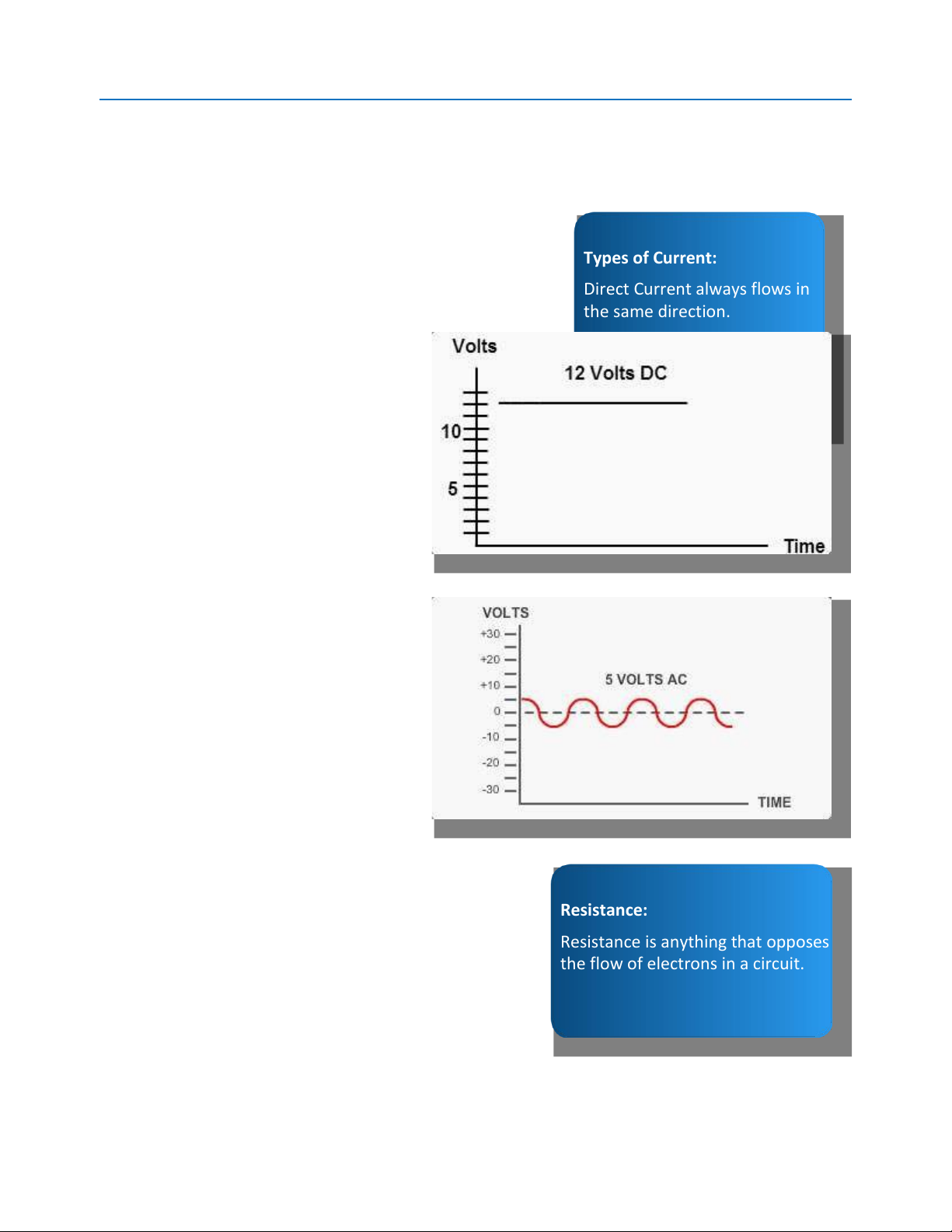
current (DC) or alternating current (AC). Types of Current:
Direct current (DC) always flows in the same direction in a
Direct Current always flows in
circuit, while alternating current (AC) flows in one direction, the same direction.
then reverses itself, and moves in the opposite direction. Alternating Current changes direction.
Batteries and other steady state devices
produce DC while AC always comes from
a moving device, such as a generator.
Technicians will find that the vast Direct
Current (DC) Flow majority of automotive
circuits are DC, whereas all household current is AC. Alternating Current (AC) Flow
Recall that in order for a current to be
AC, the current flow in a circuit must
actually change direction. In automotive
applications, alternators and wheel
speed sensors are examples of devices that produce AC Current. Resistance:
Resistance is anything that opposes
the flow of electrons in a circuit. Resistance
In an electrical circuit, anything that
opposes the flow of electrons is called
resistance. Just as voltage pushes
current through conductors, resistance limits or
reduces the number of electrons flowing in a circuit.
Tài liệu liên quan:
-
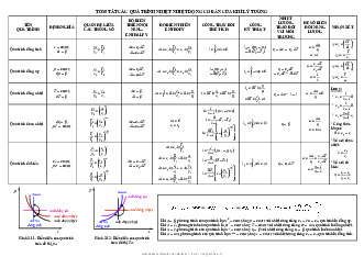
Tóm tắt Quá trình và thiết bị truyền nhiệt nhiệt động cơ bản của khí lý tưởng | Đại học Thái Nguyên
55 28 -
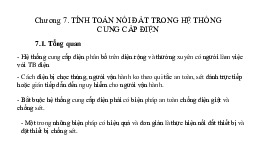
Chương 7 Tính toán nối đất trong hệ thống cung cấp điện | Đại học Thái Nguyên
44 22 -

Chương 3 Lựa chọn phương án cung cấp điện tối ưu | Đại học Thái Nguyên
34 17 -
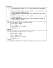
Bài tập - Các câu hỏi về máy điện không đồng bộ môn Kỹ thuật điện | Trường Đại Học Thái Nguyên
123 62 -
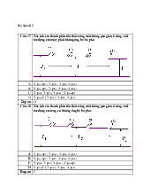
Bài Tập Số 3 Về Máy Điện - Câu Hỏi Điện Biến Áp môn Kỹ thuật điện | Trường Đại Học Thái Nguyên
85 43