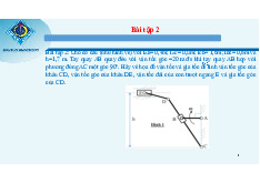
Steel Structural Engineering Project: Design of Transverse Frames | Môn Cơ học kết cấu - Đại học Cần Thơ
Steel Structural Engineering Project: Design of Transverse Frames môn Cơ học kết cấu. Tài liệu được sưu tầm gồm 130 trang, giúp bạn ôn tập tốt hơn. Mời các bạn đón xem.
Môn: Cơ học kết cấu (CN154) 10 tài liệu
Trường: Trường Đại học Cần Thơ 813 tài liệu
Tác giả:

Preview text:
lOMoAR cPSD| 23136115 Steel
Structural Engineering Project
A.P: CAO TẤN NGỌC THÂN
STEEL STRUCTURAL ENGINEERING PROJECT
Exam paper code: S1H3B6L6Q3 Design data
Design of Load-Bearing Transverse Frames for a Single-Span, Single-Story Industrial Building (Yamil
Steel Frame Workshop) with 17 Column Bays and the Following Provided Data: Transverse frame span L = 32.5 (m) Frame spacing B = 6.5 (m) Crane lifting capacity Q = 8 (T) Elevation of rail top +12 (m) Roof slope i = 15% Building length 17x6.5= 110.5 (m)
- Wind zone : II-C (Construction location: Can Tho city). - Steel material
CCT38 steel grade with a strength of:
f = 230N / mm2 = 23kN / cm 2
Preliminary selection of steel thickness t=20mm2 f = 240N / mm2 = 24kN / cm 2 v
f =380N / mm2 = 38kN / cm 2 u
Where: f : Standard yield strength of the steel.. v f u
: Standard tensile strength of the steel.
f : Design strength of the steel.
- Welding rod: N42, using manual welding method (Bh = 0.7, Bt = 0.1),
with weld strength checked using ultrasonic testing. CHAPTER I
DETERMINE THE MAIN DEMENSION
OF THE HORIZONTAL FRAME
Select initial data: -
Select the building elevation level to align with the reference elevation of ±0.000 mm for height calculations.. lOMoAR cPSD| 23136115 Steel
Structural Engineering Project
A.P: CAO TẤN NGỌC THÂN -
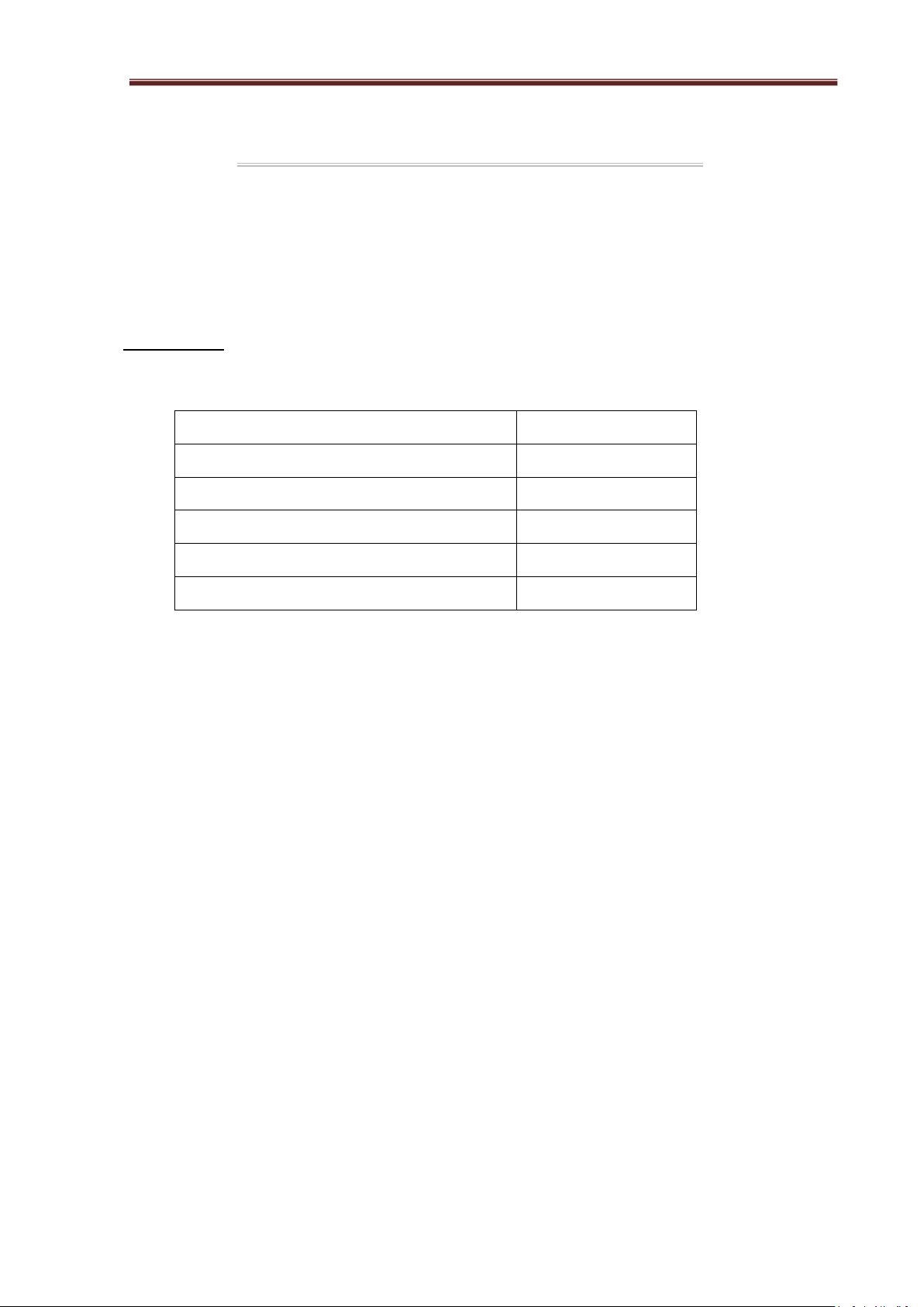
For a crane with a lifting capacity Q=8T, refer to Table II.3, page 87 of the book "Design of Single-
Story, Single-Span Industrial Steel Frames" by TS. Pham Minh Ha. The following parameters can be found:
Lifting Span Height Distance Width Base
Crane Trolley Pressur Pressure capacity gabarit slab weight e Pmax Pmin L gabarit Z weight k min Q H width G (T) G (kN) (kN) (m) k (mm) B xe k Kk (T) (mm) (mm) (T) (mm) 8 31 1010 180 5930 5100 19.62 0.605 84.7 43.5
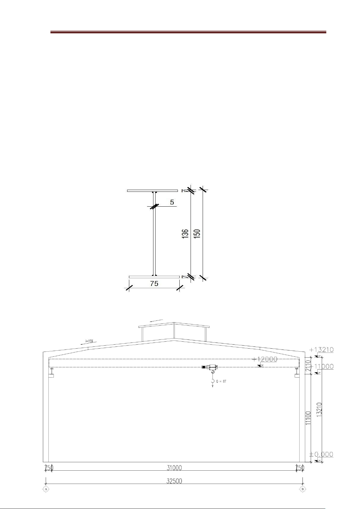
I . Vertical dimension :
- Height from crane rail to bottom of crossbeam:
H2 = Hk + bk = 1.01 + 0.2 = 1.21 (m).
With : bk = 0.2 (m) - according to the selected crane specifications.
Hk = 1.01 (m) - safety clearance between crane and crossbeam. Choose H2 = 1.21 (m).
- Height of the frame column, measured from the foundation to the bottom of the crossbeam:
H = H1 + H2 + H3 = 12 + 1.2 + 0 = 13.21 (m).
In which: H1 - rail top elevation, H1 = 12 (m).
H3 - considering the foundation level at elevation H3 = 0.
- Height of the column from the column shoulder supporting the crane girder to the bottom of the crossbeam:
Ht = H2 + Hdct + Hr = 1.21 + 0.7 + 0.2 = 2.11 (m). In which: + Hdct - crane girder height,
We have: Hdct = (1/8 – 1/10)B = (1/8 – 1/10).6.5 = (0.65 – 0.8125)m.
=> Preliminary selection Hdct= 0.7 (m).
+ Hr - height of the rail and pad, choose Hr=0.2 (m).
- Height of the column from the foundation level to the top of the column shoulder:
Hd = H - Ht = 13.21 – 2.11 = 11.1 (m). II
. Horizontal dimension :
- Considering the reference axis coinciding with the outer edge of the column (a = 0). lOMoAR cPSD| 23136115 Steel
Structural Engineering Project
A.P: CAO TẤN NGỌC THÂN
- Distance from the reference axis to the crane rail axis: L− LK 32.5−31 L1= 2= 2 =0.75(m)
With Lk = 31(m) – crane span taken from the catalog.
L= 32.5 (m) – frame span, taken according to design requirements.
- Column section height selected according to stiffness requirements:
ℎ=( ÷ ) H=( ÷ )13.21=(0.66÷0.88)(m)
choose h = 0.7 (m) = 70 (cm).
- Check the clearance between the crane and the frame:
z=L1− ℎ2 =0.75− 0.72 =0.4 (m)>zmin=0.18(m)
Preliminary section selection:
1. Preliminary selection of column dimensions and cross-sections:
- The column cross-section width is selected based on structural and stiffness requirements:
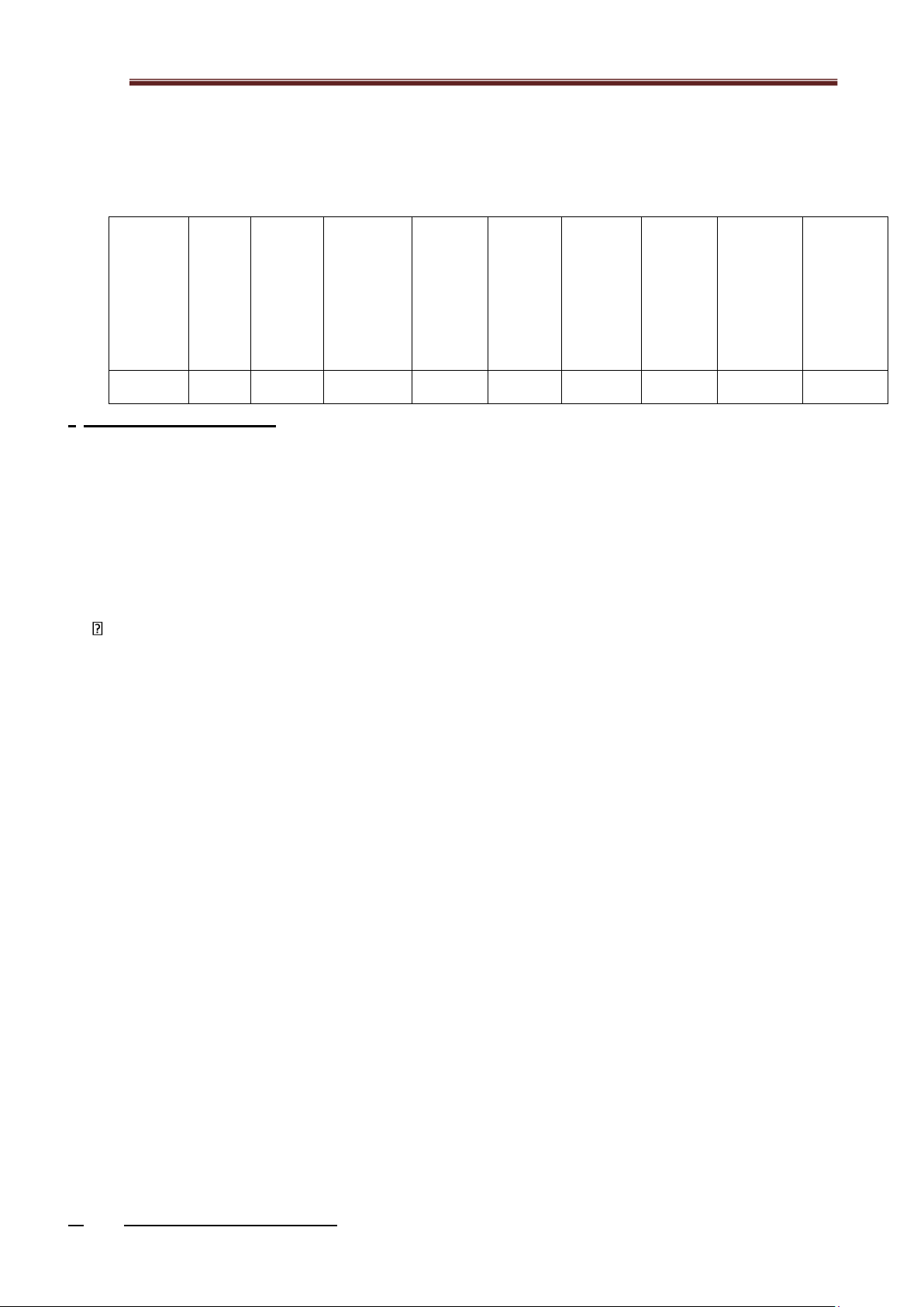
bf = (0.3÷0.5)h = (0.3÷0.5)x700 = (210 ÷ 350) mm => Choose bf = 300 mm - Web thickness: ( w
1)ℎ=(÷)×700=(10÷7) mm>6mm t = ÷ 70 => Choose tw = 8 mm. - Flange thickness: lOMoAR cPSD| 23136115 Steel
Structural Engineering Project
A.P: CAO TẤN NGỌC THÂN mm
2. Select the cross-section of the beam:
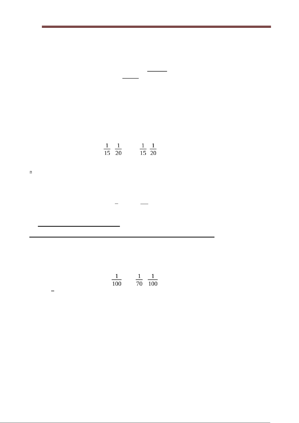
- Beam end (cross-section variation): - Head of
the beam section (change of section) ℎxl=( 1
÷)L=(÷)×32500=(541.67÷650 )mm 50 Choose ℎxl=700mm
bxl=(0.3÷0.5 )×ℎxl=(210÷350) mm
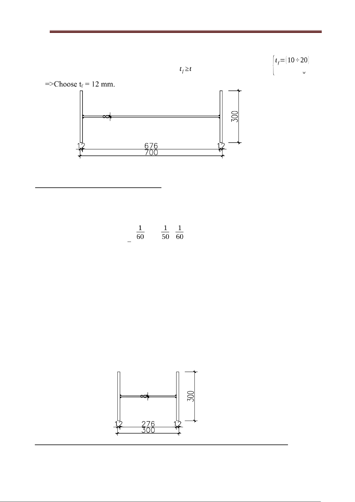
Choose bxl = 300 mm. tw = 8mm. tf = 12mm.
- End of the bar section (constant cross-
section) hxn= 300 mm bf= 300mm tw= 8mm. tf= 12mm.
3. Preliminary selection of the dimensions and cross-section of the skylight :
a. Skylight dimensions: lOMoAR cPSD| 23136115 Steel
Structural Engineering Project
A.P: CAO TẤN NGỌC THÂN
- According to architectural and lighting requirements, the roof opening is chosen to run along
the entire length of the building, except for the two end spans, with the following specifications:
+ The width of the roof opening is Lcm = (1/2 ÷ 1/5 )L →Lcm = 8m. +
The height of the roof opening is taken as Hcm = 2m.
The roof slope of the skylight is taken equal to the truss roof slope i=15%. b.
Skylight cross-section:
- Preliminary selection:I15steel section, referring to I15 steel sections available in the market,
we have the following dimensional specifications:
Figure 1.4. Preliminary selection of the skylight column cross-section lOMoAR cPSD| 23136115 Steel
Structural Engineering Project
A.P: CAO TẤN NGỌC THÂN
Figure 1.5. The main dimensions of the horizontal frame
CHAPTER II DESIGN OF BRACING SYSTEM ------
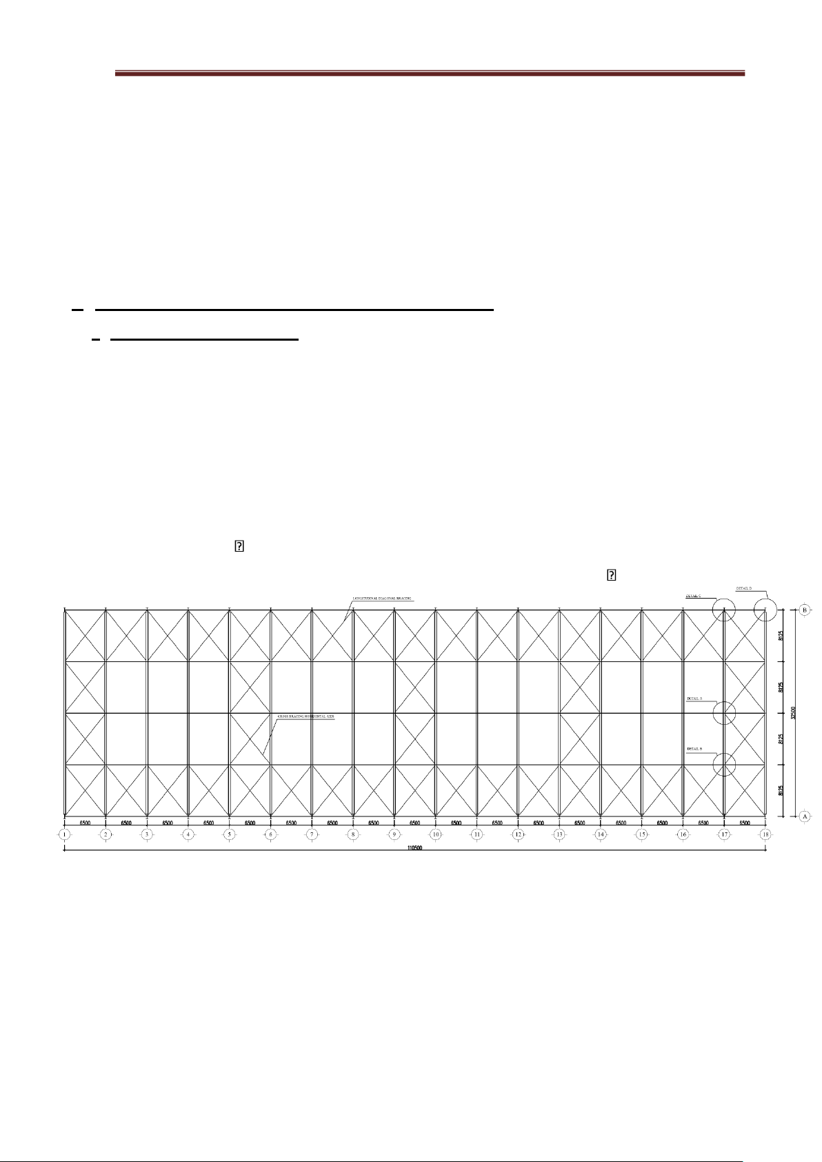
I. Roof Bracing System and Column Bracing System .
1 . Roof Bracing System .
- It is arranged in the plane of the upper wing body at both gable ends (or near the
gable ends), at the ends of the temperature blocks, and in the middle of the building
depending on its length, ensuring that the distance between the bracing is no greater than 5
column spans. The web plates of two adjacent cross beams are connected by cross-bracing members in an "X" shape.
- These cross-bracing members can be made of angle steel, round steel, or
galvanized steel cables with a diameter not less than 12 mm, or round steel with a diameter not less than 20.
=> We select the roof bracing members to be round steel with a diameter of 20.
Figure 2.1 Roof Bracing Layout Plan lOMoAR cPSD| 23136115 Steel
Structural Engineering Project
A.P: CAO TẤN NGỌC THÂN
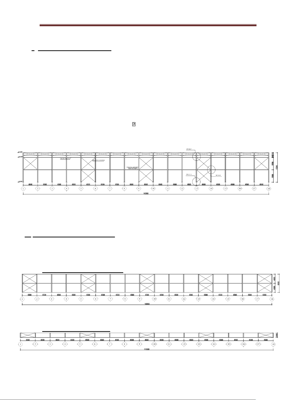
2 . Column Bracing System .
- The column bracing system serves to ensure the longitudinal stiffness of the building and
maintain the stability of the columns. It receives and transmits longitudinal forces acting on the building,
such as wind loads on the gable wall and longitudinal braking forces from the crane, down to the
foundation. The column bracing system consists of cross-bracing members arranged within the upper
and lower column spans in bays equipped with roof bracing systems.
- Since the building has a crane with a lifting capacity of 8 tons, round steel with a diameter not less than 20 mm is used.
=> Select round steel with a diameter of 20
- We select the column bracing members and column-end bracing members as C-shaped
steelsections with the designation 6CS2.5x105. The self-weight of the steel is g = 6.29 kg/m.
Figure 2.2: Column Bracing Layout Plan
II. Skylight-roof Bracing System .
- The roof bracing system at the gable is arranged similarly to the main roof bracing system;
however, the gable roof bracing system only includes the upper chord bracing and vertical bracing.
1. Upper chord bracing system .
Figure 2.3: Upper chord Bracing Layout Plan
2. Vertical bracing system .
Figure 2.4: Vertical Bracing Layout Plan
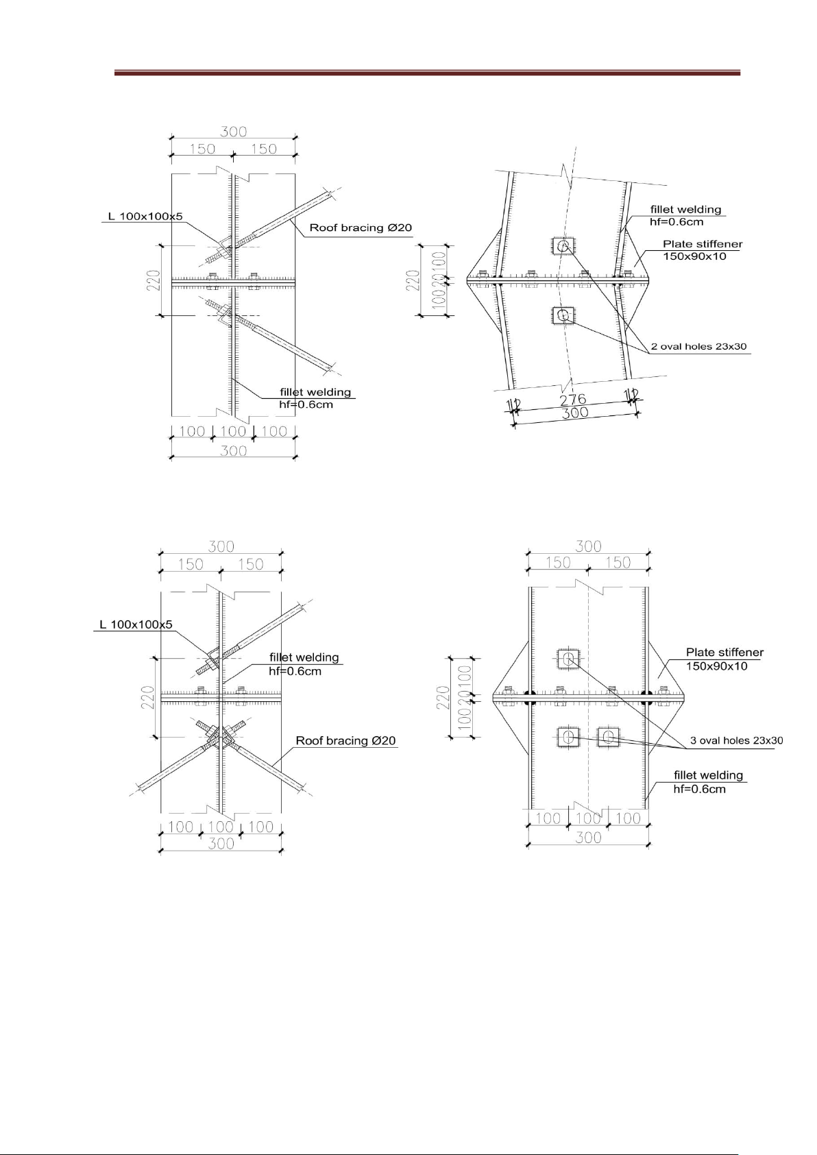
We select the column bracing members and the roof ridge bracing members as C-section steel:
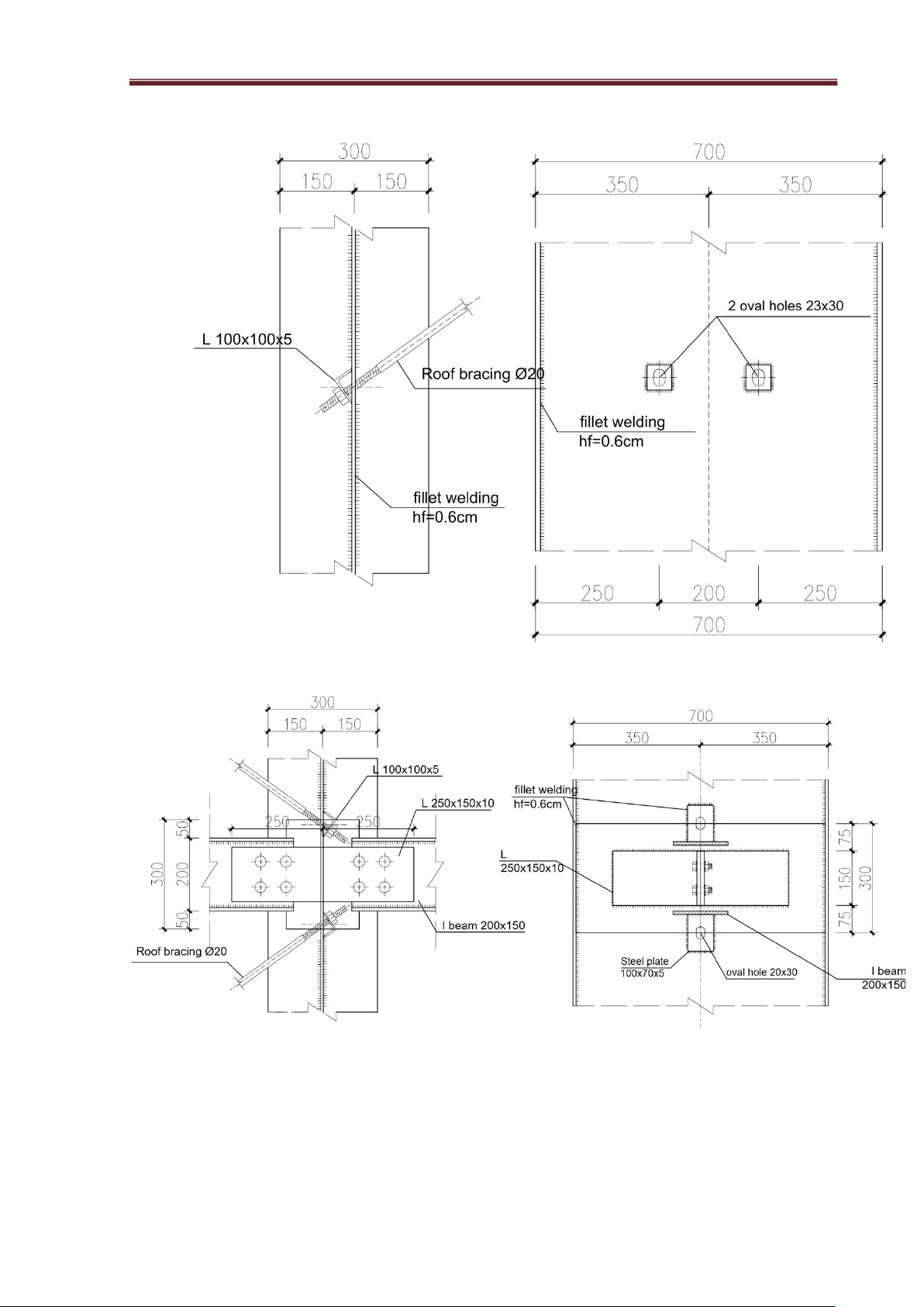
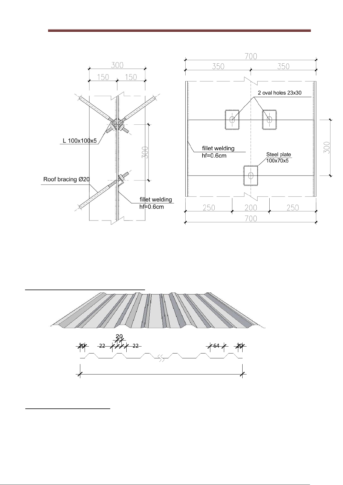
C200x65x20x3. The self-weight of steel is g = 6.29Kg/m. Details: lOMoAR cPSD| 23136115 Steel
Structural Engineering Project
A.P: CAO TẤN NGỌC THÂN DETAIL A SCALE: 1/10 DETAIL B SCALE: 1/10 lOMoAR cPSD| 23136115 Steel
Structural Engineering Project
A.P: CAO TẤN NGỌC THÂN fillet welding hf=0.6cm DETAIL C SCALE: 1/10 DETAIL D SCALE: 1/10 lOMoAR cPSD| 23136115 Steel
Structural Engineering Project
A.P: CAO TẤN NGỌC THÂN DETAIL E SCALE: 1/10 DETAIL F SCALE: 1/10 lOMoAR cPSD| 23136115 Steel
Structural Engineering Project
A.P: CAO TẤN NGỌC THÂN DETAIL G SCALE: 1/10
CHAPTER III TOLE ROOFING DESIGN --- ---
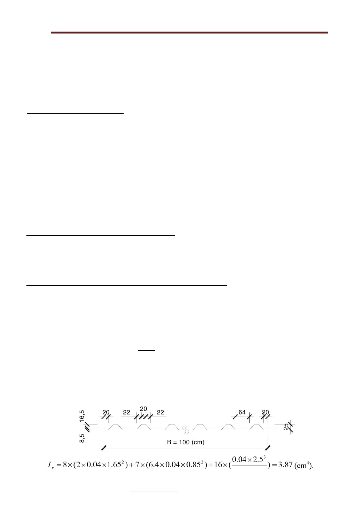
I . Geometric section characteristics . B = 100 (cm)
Figure 3.1. Cross-Section of the Steel Sheet
II. Calcualating diagram .
The corrugated sheet is calculated as a continuous beam (in the case of a continuous sheet) or a simple
beam supported by purl-ins. The cross-sectional area is calculated as shown in the a-a cross-section
diagram, with a width of B= 100 cm.
III. Load acting on corrupted sheet lOMoAR cPSD| 23136115 Steel
Structural Engineering Project
A.P: CAO TẤN NGỌC THÂN
- Including: wind load, self weight and roof live load. Roof slope is i≤15%. Therefore, the wind load
is in the opposite direction of the roof live load and the self-weight of the sheet. We choose the load
combination with the largest absolute value for calculation.
- Select the spacing of the purl-in steps on the plan as: a = 1.2m.
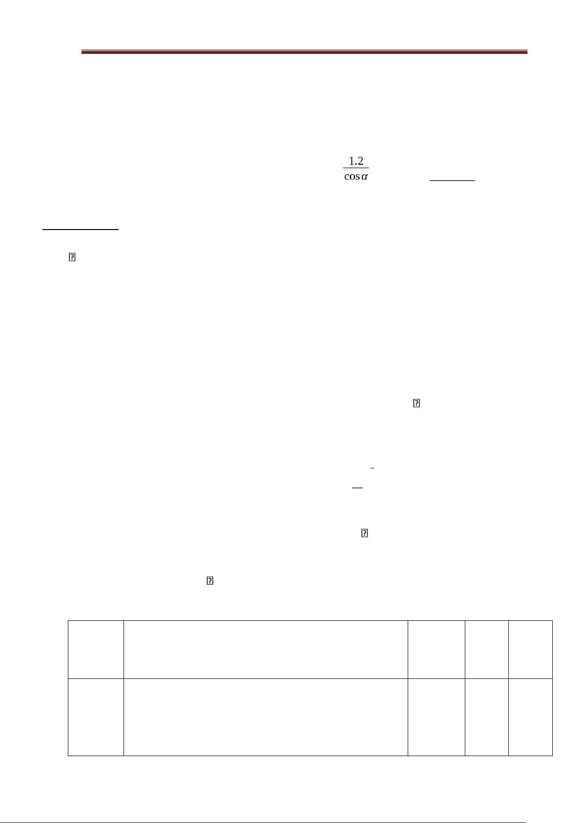
i=15%→α=arctan (0.15)=8032'=¿ a= = 1.20
=1.213(m) cos8 32' 1. Wind load :
The wind load acting on the roof is calculated according to the formula:
W k =W3s, 10.k (Ze ).c.Gf In which:
- W3 s,10 is the 3 second wind pressure corresponding to a 10 year return period: W =
is the conversion factor for win pressure form a 20 year to a 3 s,10
(γT W o)=0.852∗95=80.94 daN/m2 with γT
10 year return period, taken as 0.852
- W o is the basic wind pressure, expressed daN/m2 (TCVN 2737-2023)
- The construction site in Can tho city is taken according to zone II W o=95daN /m2
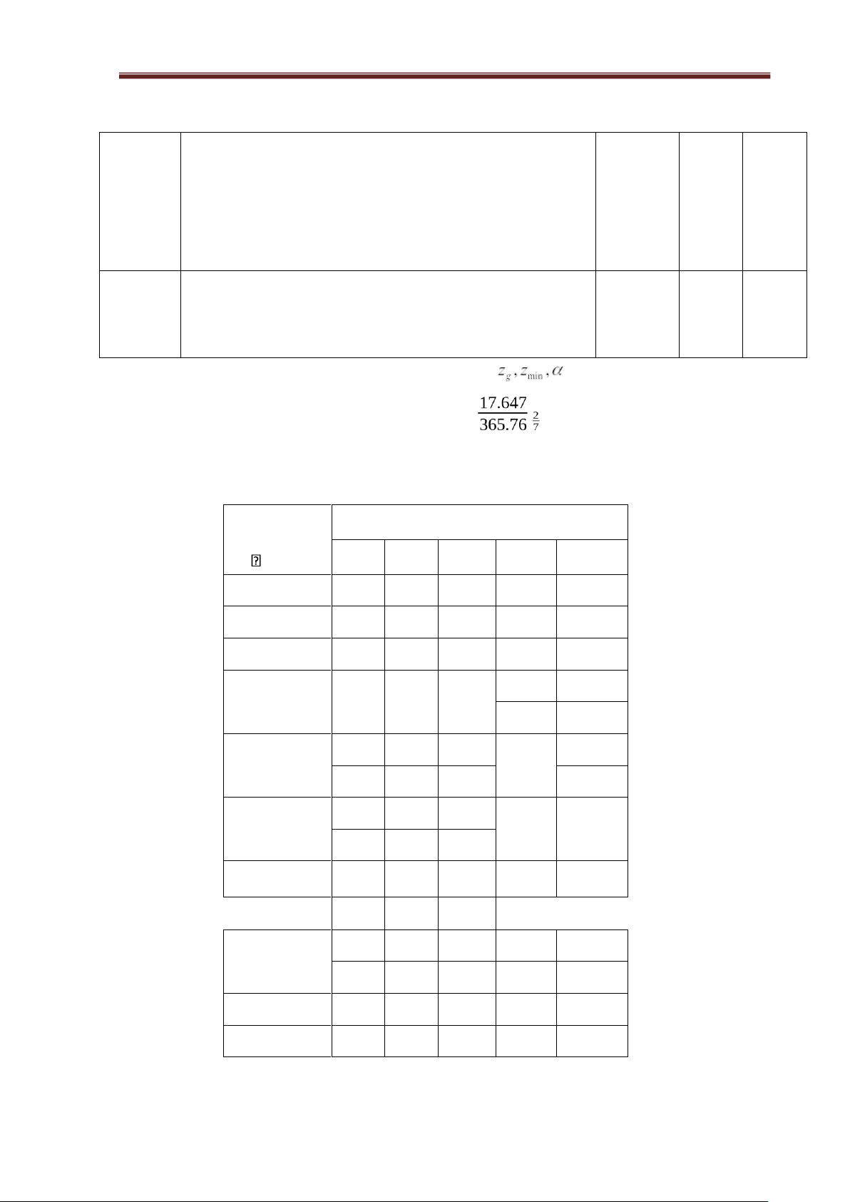
- k (ze ) is the factor according for the variation of wind pressure with height and terrain type at the equivalent height. ze 2a k
(ze )=2,01( zg ) In which:
- ze is determined according to 10.2.4(TCVN 2737-2023) ze=h
(h=13210+4437=17647mm=17.647m)
- zg is the gradient height, determined depending on the terrain type, taken from table 8, Construction
belongs to terrain type C zg=365,76
- a is the coefficient used in the power function for 3-second wind speed (averaged over a 3-second
period), determined depending on the terrain type, taken from Table 8 => a=7 Terrain
Describe the terrain type Value Value Value type zg, m zmin, α m A
Open, with no or very few obstacles no more than 1.5 213,36 2,13 11,5
m high (open coast, river surface, large lake, salt
fields, fields without tall trees...), see Figure D.1, Appendix continent D. lOMoAR cPSD| 23136115 Steel
Structural Engineering Project
A.P: CAO TẤN NGỌC THÂN B
Relatively empty, with some sparse obstacles no more 274,32 4,57 9,5
than 10 m high (suburbs with few houses, towns,
villages, open or young forests, sparsely planted
areas...), see Figure D.2, Appendix continent D.
Strongly shielded, with many obstacles close together C
10 m high or more (in cities, dense forests...), see 365,76 9,14 7,0 Figure D.3, Appendix D.
Figure 3.2. Table 8 – Values => k(ze)=2,01( ) => k(ze)= 0.845
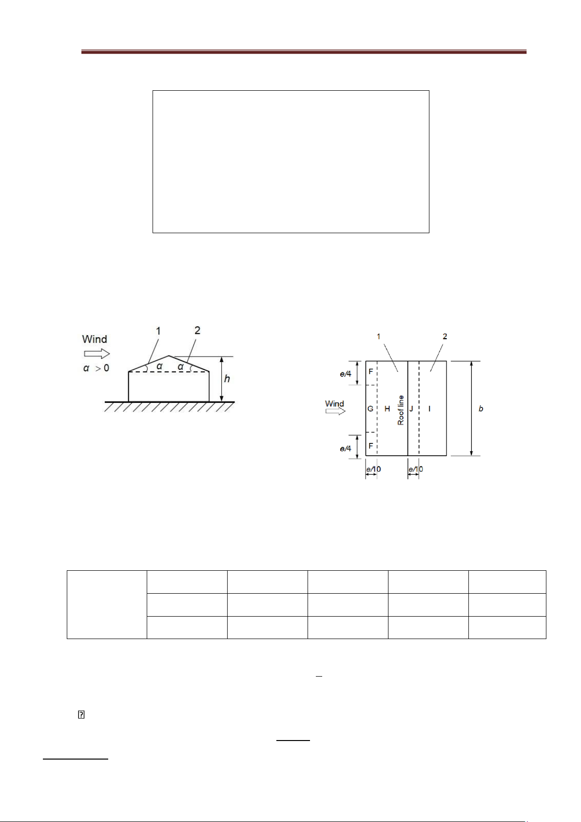
- c is the aerodynamic coefficient, determined according to 10.2.6 - Determine ce by going
through Table F.5a appendix F. Region Slope angle α, F G H I J - 45 - 0,6 - 0,6 - 0,8 - 0,7 - 1,0 - 30 -1,1 - 2,0 - 0,8 - 0,6 - 0,8 - 15 - 2,5 - 1,3 - 0,9 - 0,5 - 0,7 + 0,2 + 0,2 - 5 - 2,3 - 1,2 - 0,8 - 0,6 - 0,6 -1,7 - 1,2 - 0,6 + 0,2 5 - 0,6 + 0,0 + 0,0 + 0,0 - 0,6 - 0,9 - 0,8 - 0,3 15 - 0,4 - 1,0 + 0,2 + 0,2 + 0,2 - 0,5 - 0,5 - 0,2 30 + 0,7 + 0,7 + 0,4 - 0,4 - 0,5 - 0,0 - 0,0 - 0,0 - 0,2 - 0,3 45 + 0,7 + 0,7 + 0,6 + 0,0 + 0,0 60 + 0,7 + 0,7 + 0,7 - 0,2 - 0,3 75 + 0,8 + 0,8 + 0,8 - 0,2 - 0,3 lOMoAR cPSD| 23136115 Steel
Structural Engineering Project
A.P: CAO TẤN NGỌC THÂN
NOTE 1: When θ= 0°, Pressure changes rapidly between negative
and positive values as the angle steepens - 5° ≤ α≤ + 45°, therefore
both negative and positive values are given in this table. For this roof,
two cases need to be considered: one with all positive values and two
with all negative values. Do not consider positive and negative
values on the same side at the same time.
NOTE 1: Use linear interpolation for slope angles between values of
the same sign (do not interpolate between α=+5° and α= -5° but use
the data for flat roofs in F.2). Values equal to 0.0 are used for linear interpolation.
Figure 3.3 - Table F.5a – Coefficient ce when wind direction angle θ = 0°
Check F.4.2 - Index table of aerodynamic coefficients (TCVN 2737:2023). We choose diagram a and wind angle b) Figure 3.4 - Diagram a Figure 3.5 - Wind angle b
Check the table F.5a TCVN 2737:2023 and using interpolation method we can calculate the value o
region with angle α=8032' fall between 50 and 150. F G H I J -1.417 -1.059 -0.494 -0.529 -0.295 8032' 0.071 0.071 0.071 -0.529 -0.741
Figure 3.6 - Interpolation Table of 8032' angle
- We choose the highest number: Ce= C = -1.417 h
- Gf is the gust factor, => Gf = 0.85 + 1010 = 0.868 -
Wk = W3s,10.k(ze).c.Gf =80.94*0.845*(-1,417)*0.868= -84.122kg/m
=>q1= -84.122 * 2.1 = -176.656 (kg/m) 2.Live load on roof lOMoAR cPSD| 23136115 Steel
Structural Engineering Project
A.P: CAO TẤN NGỌC THÂN
q2=γ n×30×B=1.3×30×1=39kg/m In Which:
+γn=1.3 is the overload factor.
+B:The area of influence on the metal sheet, calculated per 1m for structural analysis.B=100(cm)
3 . Weight of a sheet of metal
q3=gtc ×ng ×B=3.768×1.1×1=4.145kg/m
gtc=1.2×δ ×γ T=1.2×0.0004×7850=3.768kg/m2 Meanwhile:
+ gtc : Standard weight of tole;
+ δ : thickness of tole = 0.4mm;
+ The overload factor 1.2 includes the corrugated of tole;
+ γT = 7850 (kg/m2) : Specific weight of roofing material;
+ ng=1.1 : is the overload factor ;
+B : Calculated width of corrugated tole, B=100 cm
4. Combination of loads acting on the tole :
Choose a dangerous combination from the following combinations:
- CASE 1 : qc1 = q1 + q3 = -176.656 + 4.145= -172.511 (kg/m).
- CASE 2 : qc2 = q2 + q3 = 39 + 4.145 = 43.15(kg/m).
5 . Internal force and cross section check of corrugated tole
- Internal forces: Primarily calculating the maximum moment (Mmax) of the corrugated sheet.
Using methods from strength of materials, the internal forces of the structural components
corresponding to the load combinations can be determined CASE 1. 1 2 1 2
M max=8 qc1l =8 ×172.511×1.2 =31.052(kg.m)
Geometric Characteristics of the Steel Sheet Section: 12 I x 3.87 3 lOMoAR cPSD| 23136115 Steel
Structural Engineering Project
A.P: CAO TẤN NGỌC THÂN W x=
ymax =1.65=2.345(cm ) -
Check the cross-section of the steel sheet as a bending member. + Strength condition:
MWmaxx 31.0522.345×100
(kg/cm2)<f ∗γ
c=2300(kg/cm2) σ== =1324.179
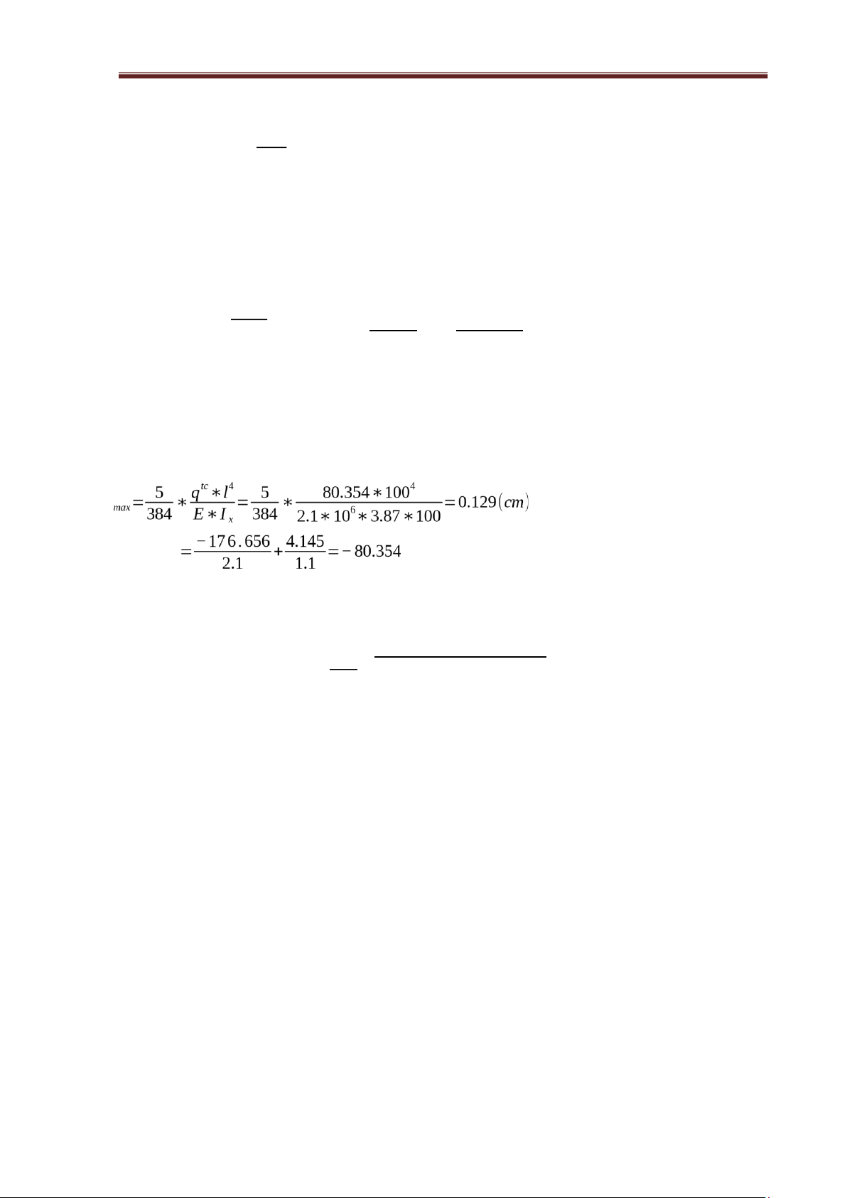
With : γ = 1 : working condition coefficient. c f : steel design strength. + deflection criteria: f With : qtc (kg/m)
E = 2,1*106 (kg/cm2) : elastic modulus of steel. f max 0.129 f 1 = =0.0013< = =0.005 L 100 [ L] 200
So that: the metal sheet is designed to meet the conditions for strength and deflection. lOMoAR cPSD| 23136115 Steel
Structural Engineering Project
A.P: CAO TẤN NGỌC THÂN CHAPTER IV
DESIGN OF THE PURLIN SYSTEM
I.Design of the purlin system.
Roof purlins in light steel frames often use cold-rolled forming steel thin (less than 3mm),
C or Z cross section. For the frame being designed, choose the purlin is cold steel with a C-
shaped section. The calculation diagram of the C purlin is a simple beam. Purlin calculated
as a member subjected to oblique bending (bending in 2 planes). I.Calculate the purlin system.
1.Preliminary selection of purlins.
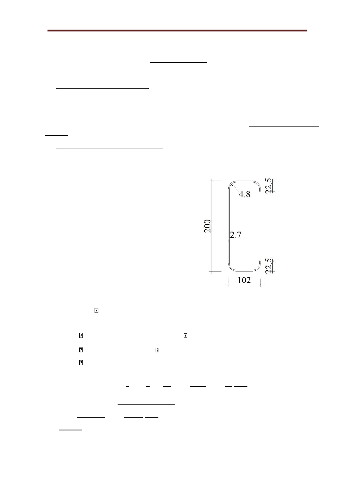
Based on the purlin catalog, choose a C-shaped purlin with number 8CS4x105 with the
following the cross-sectional characteristics are as follows: D
= 200(mm); B = 102 (mm); t = 2.7 (mm); d = 22.5 (mm); R = 4.8 (mm);
Cross section area:11.48(cm2); Ix = 774.19 (cm4);
Wx = 76..04 (cm3); Iy = 156.5 (cm4); Wy = 22.61 (cm3);
x0= 3.25 (cm); Figure 4.1. Purlin cross section area
- Purlins self-weight gtcxg=8.93(kg/m)
- Distance arranged between purlins on selected plan a=1.2 (m)
1.Load acting on purlins:
Slope i =15% Angle α=8o32' (sin α=0.148;cos α=0.989)
# Case 1: Effective loads include:
Self weight of roofing sheet: gtc 3.768kg / m2 ;
Purlin self-weight:gtcxg 8.93 kg / m (Selected in catalog);
Live load roof repair:ptc=30kg/m2(In TCVN 2737-2023); =>Total load acting on
purlins: qtc=(gtccos+ p(tcα))×a +gtcxg=(3.7680.989+30)×1.2 +8.93=49.902kg/m tc tc q=
(ng ×gcos+γ n× p )×a+ng
×gtcxg=(1.1×3.7680.989+1.3×30)×1.2 +1.1×8.93=62.173kg/m (α)
# Case 2: Including the impact of wind load on purlins:
- Wind load acting on the beam:
qtcg =W k ×a=84.122×1.2=100.946 kg/m2 qg=W
k ×a×n=84.122×1.2×2.1=211.987 kg/m Where: lOMoAR cPSD| 23136115 Steel
Structural Engineering Project
A.P: CAO TẤN NGỌC THÂN n =2.1: overload factor
=>Total load action on the purlin: qtc gtc tc 100.946 3.768
q cos α cos α ×a−gxg= 0.989 − 0.989
×1.2−8.93=88.567 kg/m ( ) ( ) q n ×gtc tc 211.987 1.1×3.768
q×a−ng×gxg= 0.989 − 0.989
×1.2−1.1×8.93=199.493kg/m
Because q*> q so we only consider case 2 when the purlin bears the load q*=199.493kg/m;
Distributed the load q* into 2 direction of action.
Figure 4.2. Diagram of distributed load acting on purlins
- Distributed the loads into 2 direction x-x and y-y: q tt
x =q∗×cos (α )=199.493×0.989=197.299kg/m qxtc kg/m
qtty=q∗×sin(α)¿199.493×0.148=29.525kg/m qtcy kg/m
2 . Internal force is generated in the purlin :
- Purlins are structural members subject to oblique bending; internal forces is calculated in 2 direction x-x and y-y: tt tt tt qx ×l2 qx ×B2 197.299×6.52 M x = 8= 8 = 8
=1041.985kg.m=104198.5kg.cm tc tc
qx ×l2 qtcx ×B2 87.593×6.52 lOMoAR cPSD| 23136115 Steel
Structural Engineering Project
A.P: CAO TẤN NGỌC THÂN M x = 8= 8 = 8
=462.601kg.m=46260.1kg.cm tt
qtty ×l2 qtty ×B2 29.525×6.52 M y= 8= 8 = 8
=155.929kg.m=15592.9kg.cm tc
qtcy ×l2 qtcy ×B2 13.108×6.52 M y = 8= 8 = 8
=69.227kg.m=6922.7kg .cm
3.Check purlin cross-section : a) Check durability:
Using this formula to check the durability of the purlin cross-section: M M W x W y c M x M y 104198.5 2
σ=W x + W y = 76.04
+=2059.958kg/cm ≤f ×γ c=2100×1=2100kg/
22.61 → The purlin cross-section meets the durability condition:
a) Check the deflection:
Using this formula to check the deflection: Deflection in 2 directions: 5 qtcx ×B4 5 − 2 f x=384
E×I x =384 87.593×10 ׿¿ tc 4 5 q y ×B 5 −2 f y=384
E×I y =384 13.108×10 ׿¿
→Deflection of purlin:f cm f 1.558 f 1
→ = =0.0024<[ ]= =0.005 l 650 l 200
=> Purlin cross-section meets the deflection conditon;
-Select the purlin cross-section that meets the requirements. lOMoAR cPSD| 23136115 Steel
Structural Engineering Project
A.P: CAO TẤN NGỌC THÂN CHAPTER V
DESIGN WALL FRAME SYSTEM
I. PRELIMINARY SELECTION OF WALL FRAME SECTION .
The frame system consists of two main types. The wall frame system for sheet cladding
uses steel bars with common cross-sections such as: C, Z, I, box steel. The wall support
system for masonry walls often uses I-shaped steel. Because the structure has a normal bay B
= 6.5 (m), Based on the wall rib catalog, choose a C-shaped wall rib with a serial number
6CS2,5x105 The cross-sectional characteristics are as follows: D = 150(mm);
B = 64 (mm); t = 2.7 (mm); d =
22.5 (mm); R = 4.8 (mm); Cross section area:8.06(cm2); Ix = 287.62 (cm4); Wx = 37.69 (cm3); Iy = 45.37 (cm4); Wy = 10.64 (cm3);
x0= 2.1(cm); Figure 5.1. Wall rib cross-section. - Self-weight of the wall
rib:gst=6.29(kg/m) II.
LOAD ACTING ON THE SIDE OF THE WALL
Loads acting on wall ribs include: weight of wall panels (tole), self-weight of wall rib beams and wind load.
We choose the distance between the wall beams a = 1m. Then we need to arrange: -
For houses: n = 1+(13.21/1) = 14.21 => choose 15 wall beams st -
For roof door: n = 1+(2/1) = 3=> choose 3 wall beams st
1.Vertical direction : (Direction x-x);
The wall frame beam bears its self-weight and the weight of the wall panels q tc
x =gtc×a+gst=3.768×1+6.29=10.058kg/m q tt
x =gtc ×a×ng+gst ×nst=3.768×1×1.1+6.29×1.1=11.064kg/m
Where:nst=nxg=ng=1.1
Tài liệu liên quan:
-
Tính toán cầu thang bê tông cốt thép 2 | Môn Cơ học kết cấu - Đại học Cần Thơ
172 86 -
Bài Tập Chương 2 - Cơ Cấu và Vận Tốc Quay | Môn Cơ học kết cấu - Đại học Cần Thơ
109 55 -
Term paper on steel structures | Môn Cơ học kết cấu - Đại học Cần Thơ
130 65 -
Bài Tập Bài 2: Phân Tích Dung Trọng và Độ Chứa Nước | Môn Cơ học kết cấu - Đại học Cần Thơ
108 54 -
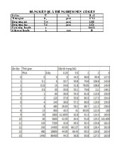
Bài 5 - Thí nghiệm nén cố kết và kết quả phân tích | Môn Cơ học kết cấu - Đại học Cần Thơ
166 83