Tiểu luận Cơ sở điều khiển điện đề tài "Footstep power generation" | Đại học Sư phạm Kỹ thuật Thành phố Hồ Chí Minh
Tiểu luận Cơ sở điều khiển điện đề tài "Footstep power generation" của Đại học Sư phạm Kỹ thuật Thành phố Hồ Chí Minh với những kiến thức và thông tin bổ ích giúp sinh viên tham khảo, ôn luyện và phục vụ nhu cầu học tập của mình cụ thể là có định hướng ôn tập, nắm vững kiến thức môn học và làm bài tốt trong những bài kiểm tra, bài tiểu luận, bài tập kết thúc học phần, từ đó học tập tốt và có kết quả cao cũng như có thể vận dụng tốt những kiến thức mình đã học vào thực tiễn cuộc sống. Mời bạn đọc đón xem!
Môn: Cơ sở điều khiển điện 3 tài liệu
Trường: Trường Đại học Sư phạm Kỹ thuật Thành phố Hồ Chí Minh 4.4 K tài liệu
Tác giả:


Preview text:
lOMoARcPSD| 36086670
HO CHI MINH CITY UNIVERSITY OF TECHNOLOGY AND EDUCATION
FACULTY FOR HIGH QUALITY TRAINING BASIC ELECTRONICS
FOOTSTEP POWER GENERATION STUDENT REPORT Supervisor Dr. Tran Vu Hoang Submitted by La Gia Bao Le Tran Vu Hoang December 12 th ,2021 lOMoAR cPSD| 36086670 lOMoARcPSD| 36086670
Table of Contents
ACKNOWLEDGEMENTS ....................................................................................................... i
ABSTRACT ................................................................................................................................ i
LIST OF PARTICIPANT MEMBERS ................................................................................... ii
LIST OF FIGURES.................................................................................................................
CHAPTER 1: INTRODUCTION...........................................................................................1
1.1. Problem statement...............................................................................................................1
1.2. Description of the Project....................................................................................................5
1.3. Benefits of the system..........................................................................................................5
1.4. Objectives............................................................................................................................5
CHAPTER 2: BACKGROUND CONTENT..........................................................................6
2.1. Introduction to Piezoelectricity ...........................................................................................6
2.1.1. Piezoelectric effect ..................................................................................................6
2.1.2. Principle of operation..............................................................................................6
2.1.3. Piezoelectric materials.............................................................................................7
2.1.4. Connection of Piezoelectricity.................................................................................7
2.2. Full-wave bridge rectifier....................................................................................................9
2.3. Boost converter..................................................................................................................11 lOMoARcPSD| 36086670
2.4. Voltage regulator circuit.....................................................................................................12
CHAPTER 3: DESIGN AND IMPLEMENTATION..................................................14
3.1. Block diagram...........................................................................................................14
3.2. Principle of Footstep power generation.....................................................................15
CHAPTER 4: SIMULATION AND ANALYSIS..........................................................16
4.1. Boost converter.........................................................................................................16
4.2. Oscillating circuit......................................................................................................17
4.3. Series regulator circuit...............................................................................................18
4.4. Simulation.................................................................................................................19
CHAPTER 5: RESULT AND CONCLUSION............................................................22
REFERENCE.........................................................................................................................23 lOMoARcPSD| 36086670 ACKNOWLEDGEMENTS
Reality has always shown that any success is associated with the support and help of
those around, whether the help is more or less, direct or indirect. During the time from the
beginning of the essay until now, we have received the attention, guidance and help of
teachers, family and friends around.
With extremely deep gratitude, we would like to express our sincerest thanks from the
bottom of our hearts to the teachers at Ho Chi Minh City University of Technology and
Education for using our knowledge and enthusiasm to achieve this goal. impart to us
valuable knowledge during our time at school.
We whole heartedly express our thanks to, Dr. Tran Vu Hoang, Project Supervisor, for
sparing time to go through every tiny detail and give his valuable suggestions to make this project and report a success.
We are mainly indebted to the authors of many references and articles which were used as the reference. ABSTRACT
Electricity is a very important resource in human's daily life. Its demand is increasing
day by day. Modern technology requires large amounts of electrical energy for different
activities. Power generation and its use efficiently is one of the issues. Nowadays numbers
of power sources are present, non-renewable & renewable, but still we can’t overcome our
power needs. In this project we are doing generation of power that converts kinetic energy
to electric energy caused by external force or intake pressure. Power can be created
naturally through daily activities such as walking or running. The generated power will be
stored and then we can use it for the purpose of providing electricity efficiently.
This kind of system is subjected to a force acting on the contact surface when people
walk on the steps or that of the platform. Power will be generated by gravity of the person. i lOMoARcPSD| 36086670
The surface will be compressed and an AC current will be generated. The control
mechanism carries piezoelectric sensor, this mechanical energy applied on the crystal into
electrical energy. When there is some vibrations, stress or straining force exerted by foot
on a flat platform. This is the phenomenon of piezoelectric effect. AC current when passing
through the diode bridge circuit will convert into DC current. Then it will stabilize the
voltage and increase the voltage to be usable.
This project seeks to establish an environmentally friendly, automatic and safe way of
generating electricity from human movement. Such a system can be highly efficient for
installation in places where frequent expectation the movement of large numbers of people
such as in educational institutions, universities and stations, airports, entrances, shopping malls and pedestrian streets.
LIST OF PARTICIPANT MEMBERS
1st semester 2021-2022
TOPIC: FOOTSTEP POWER GENERATION No Full name Student’s ID Job division
Find out the topic, write a report, 01 La Gia Bảo 20151014 make power point, design, calculation.
Find out the topic, write a report, 02 Lê Trần Vũ Hoàng 20151005
circuit simulation, calculation, design lOMoARcPSD| 36086670 LIST OF FIGURES
Figure 1.1: Nuclear Energy Production..............................................................................1
Figure 1.2: Coal Energy Production...................................................................................2
Figure 1.3: Solar Energy Production..................................................................................2
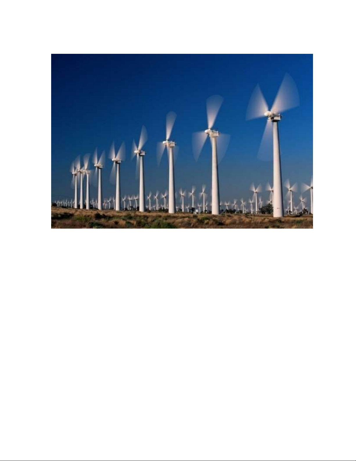
Figure 1.4: Wind Energy Production..................................................................................3
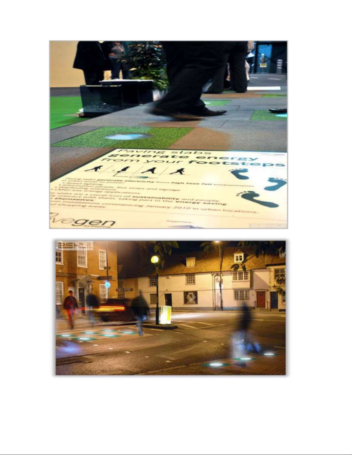
Figure 1.5: Application of Footstep Generation.................................................................4
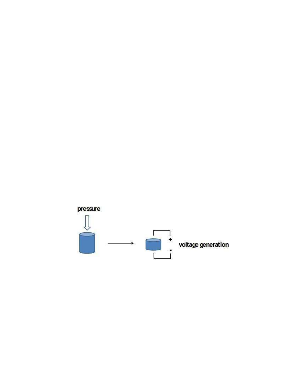
Figure 2.1: Piezoelectric effect when creating pressure......................................................6
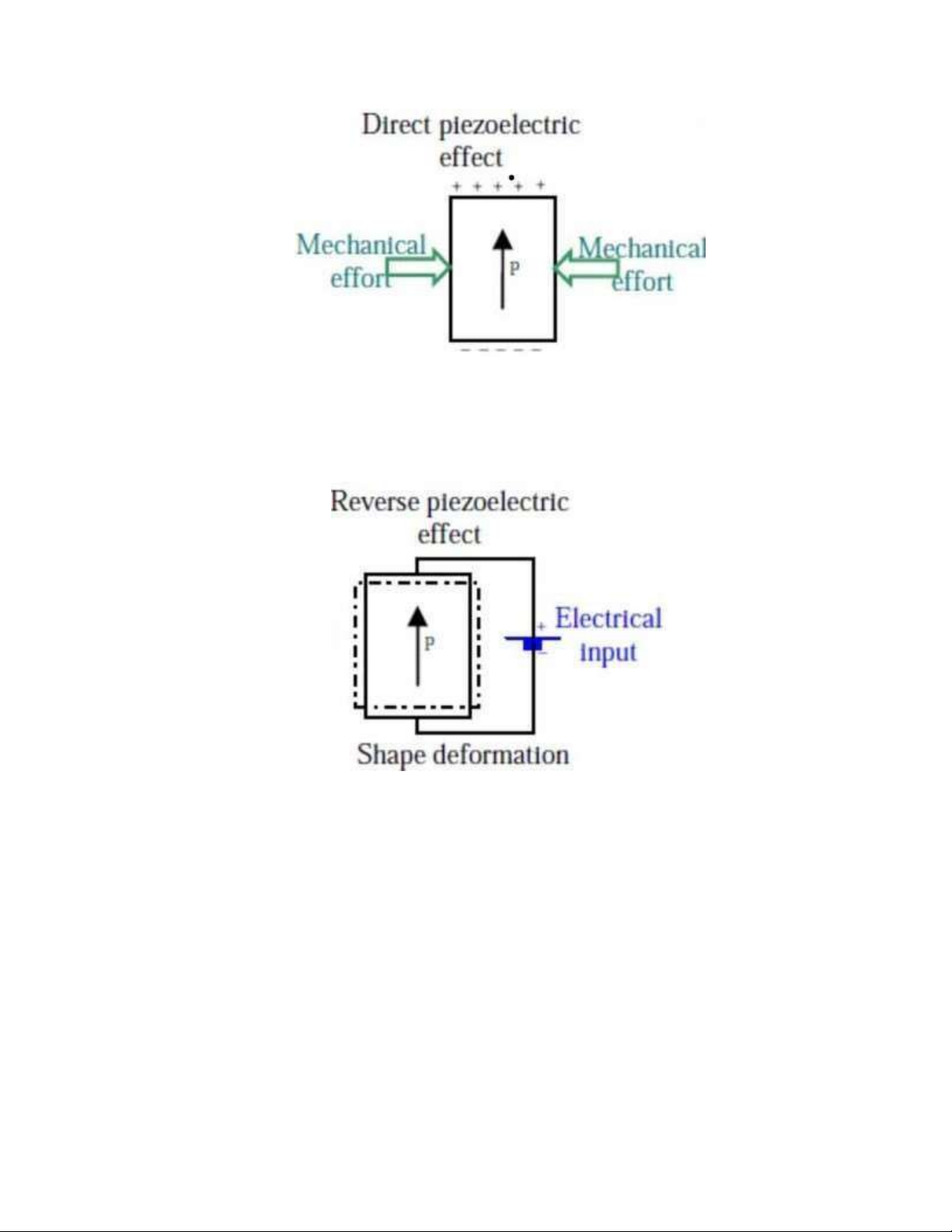
Figure 2.2: Direct piezoelectric effect................................................................................7
Figure 2.3: Reverse piezoelectric effect.............................................................................7
Figure 2.4: Value of Piezoelectric sensor of each connection.............................................8
Figure 2.5: Value of the series-parallel connection.............................................................9
Figure 2.6: Positive half-cycle..........................................................................................10
Figure 2.7: Negative half-cycle........................................................................................10
Figure 2.8: Boost converter circuit...................................................................................11
Figure 2.9: When MOSFET switch on.............................................................................12
Figure 2.10: Series regulator block diagram.....................................................................13
Figure 3.1: Block diagram of Footstep power generation.................................................14
Figure 4.1. Boost converter circuit...................................................................................16
Figure 4.2: IC 555............................................................................................................18
Figure 4.3: Series regulator circuit...................................................................................19 lOMoARcPSD| 36086670 iii
Figure 4.4: Connection of Piezoelectric sensor................................................................20
Figure 4.5: Simulation circuit...........................................................................................20
Figure 4.6: The time period.............................................................................................21
Figure 4.7: The voltage after boost...................................................................................21
Figure 4.8: The voltage after regulator.............................................................................21 lOMoARcPSD| 36086670
CHAPTER 1: INTRODUCTION
1.1 Problem statement
Problem statement: Energy is nothing but the ability to do the work. In day-to-day life,
Electricity is most commonly used energy resource. Now-a-days energy demand is
increasing and which is lifeline for people. Thus, this project was driven by the need for a
device that could generate electricity from human movement, especially footsteps.
The urgency of project: There are many sources from which electrical energy can be
generated. The main energy sources include coal, natural gas, petroleum and nuclear power.
Most of these sources have disadvantages environmental effects including air pollution; for
example: coal energy production has become one of the important causes of global warming. lOMoARcPSD| 36086670
Figure 1.1: Nuclear Energy Production
Figure 1.2: Coal Energy Production
There by an alternative source must be discovered, many people proposes for solar
energy, but it is going to be a costliest affair, moreover availability of solar energy is poor
particularly in rainy & winter seasons, as a result it is not dependable. As the availability of
conventional energy declines, there is need to find alternate energy sources lOMoARcPSD| 36086670
Figure 1.3: Solar Energy Production
Figure 1.4: Wind Energy Production
Application of project: Electricity has become important resources for human being
hence, it is needed that wasted energy must have to utilize, walking is the most common
activity done by human being while walking energy is wasted in the form of vibration to
the surface. And this wasted energy can be converted into electricity. This project gives
idea about how wasted energy is used in walking or running and being applied widely and
efficiently in some places where frequent expectation the movement of large numbers of
people such as in educational institutions, universities and stations, airports, entrances,
shopping malls and pedestrian streets. lOMoARcPSD| 36086670 lOMoARcPSD| 36086670
Figure 1.5: Application of Footstep Generation
1.2. Description of the Project
By reviewing and analyzing all these critical problems, designing new form of renewable
energy such as piezoelectricity would be a perfect option in which it is useful for domestic
application. The use of walking is increasing day by day when we are stepping amount of
this wasted energy is utilized and converted to electricity by Piezoelectric effect.
Piezoelectric effect is the effect of specific materials to generate an electric charge in
response to applied mechanical stress. It is not only considered an unlimited source of
energy but also very clean and environment friendly
1.3. Benefits of the system
No population: Unlike thermal energy, biomass production or hydro energy,
piezoelectricity does not lead to any kind of pollution nor does it cause any harm to the environment and surroundings.
No rehabilitation: Instead of destroying thousands of acres of lands, piezoelectricity
makes judicial use of it. With all its apparatus laying under the ground, a piezoelectric tile
instead of removing people from the area, asks for more populace to join in.
Independence in conditions weather: Is functional on sunny, cloudy, dry, windy and
wet days 1.4. Objectives
The aim of this research is to harvest energy from footstep using piezoelectric disk based
on the concept of polarization. The objectives of the study are as follow:
To produce renewable electricity from footstep using piezoelectric disk placed along a pathway.
To reduce the cost for power generation besides increasing the efficiency of power generation
To replace with available energy sources through human movement
To protect the natural environment beside that improving health through physical activities lOMoARcPSD| 36086670
CHAPTER 2: BACKGROUND CONTENT
2.1. Introduction to Piezoelectricity
The direct piezoelectric effect was first seen in 1880 and was initiated by the brothers
Pierre and Jacques Curie. By combining their knowledge of pyroelectricity with their
understanding of crystal structures and behaviours, the Curie brothers demonstrated the first
piezoelectric effect by using crystals of tourmaline, quartz, topaz, cane sugar, and Rochelle salt.
The piezoelectric effect finds many applications such as the production and detection of
sound, generation of high voltages, electronic frequency generation, high voltage and power
sources, sensor, piezoelectric sensor, ...
2.1.1. Piezoelectric effect
Piezoelectricity, also called the piezoelectric effect. This piezoelectric effect has two
properties. First one is the ability of certain materials to generate an AC voltage when stress
is applied. Second one is the converse effect, the generation of stress when an electric field
is applied. That means material used as a power harvesting medium
Figure 2.1: Piezoelectric effect when creating pressure
2.1.2. Principle of operation
When piezoelectric material is placed under mechanical stress, a shifting of the positive
and negative charge centres in the material takes place, which then results in an external electrical field. lOMoARcPSD| 36086670
Figure 2.2: Direct piezoelectric effect
When reversed, an outer electrical field either stretches or compresses the piezoelectric material.
Figure 2.3: Reverse piezoelectric effect
2.1.3. Piezoelectric materials
There are many materials, both natural and man-made, that exhibit a range of
piezoelectric effects. Some naturally piezoelectric occurring materials include Berlinite
(structurally identical to quartz), cane sugar, quartz, Rochelle salt, topaz, tourmaline, and
bone (dry bone exhibits some piezoelectric properties due to the apatite crystals, and the
piezoelectric effect is generally thought to act as a biological force sensor lOMoARcPSD| 36086670
2.1.4. Connection of Piezoelectricity
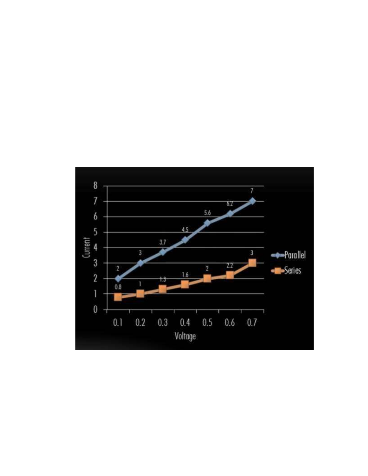
The Piezoelectric sensor is very special. According to experimenters and scientists, when
varying forces are applied on the Piezo material, different voltage readings corresponding
to the force are displayed. And when it is connected series or parallel, the value of the
voltage and the current are extremely complicated because it depends on the forces which
are applied and the material of the piezoelectric sensor. And we found information like
figure 2.4, which presented the value of the voltage and the current of each connection. As
the figure 2.4, we can see that the voltage of both connections is very small and we have to use more than one sensor.
Figure 2.4: Value of Piezoelectric sensor of each connection
It can be seen from the graph that the voltage from a series connection is good but the
current obtained is poor, whereas the current from a parallel connection is good but the
voltage is poor. But this problem is rectified in a series- parallel connection where a good
voltage as well as current can be obtained. lOMoARcPSD| 36086670
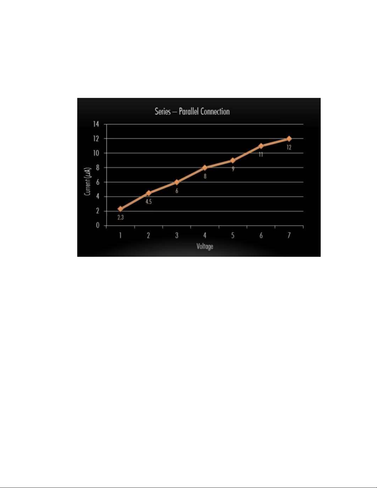
To fix the problem of the voltage of the both connections, we have to combine
seriesconnection and parallel-connection. As the figure 2.5, the series-parallel combination
not only provides an equally good voltage and current ratio but also reduces the net
resistance offered by the circuit.
Figure 2.5: Value of the series-parallel connection
2.2. Full-wave bridge rectifier
In this project, the electronic circuit requires a DC power supply to power various
electronic basic components from the available AC mains supply. To convert the input AC
to DC output, we use full-wave bridge rectifier. The circuit consists of 4 diodes. The four
diodes are connected in a closed-loop configuration to efficiency convert the AC to DC.
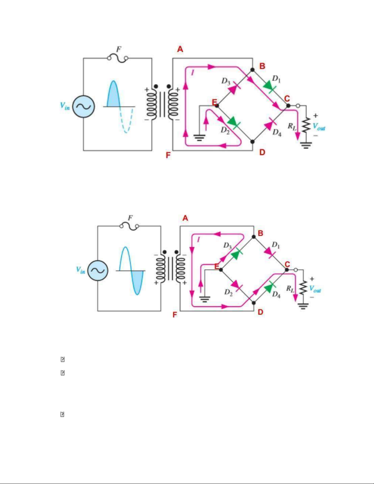
The principle of the full-wave bridge rectifier:
During the positive half-cycle of the input, D1 and D2 are forward-bias and conduct
current. D3 and D4 are reverse bias. lOMoARcPSD| 36086670
Figure 2.6: Positive half-cycle
During the negative half-cycle of the input, D3 and D4 are forward-bias and conduct
current. D1 and D2 are reverse bias.
Figure 2.7: Negative half-cycle The
advantage of full-wave bridge rectifier:
Don’t need a center-tapped (CT) so the price is low cost
In a bridge rectifier, the electric current is allowed during both positive and
negative half cycles of the input AC signal. Hence, the output DC signal is almost equal to the input AC signal.
The DC output signal of the bridge rectifier is smoother than the output DC signal of a half-wave rectifier. lOMoARcPSD| 36086670
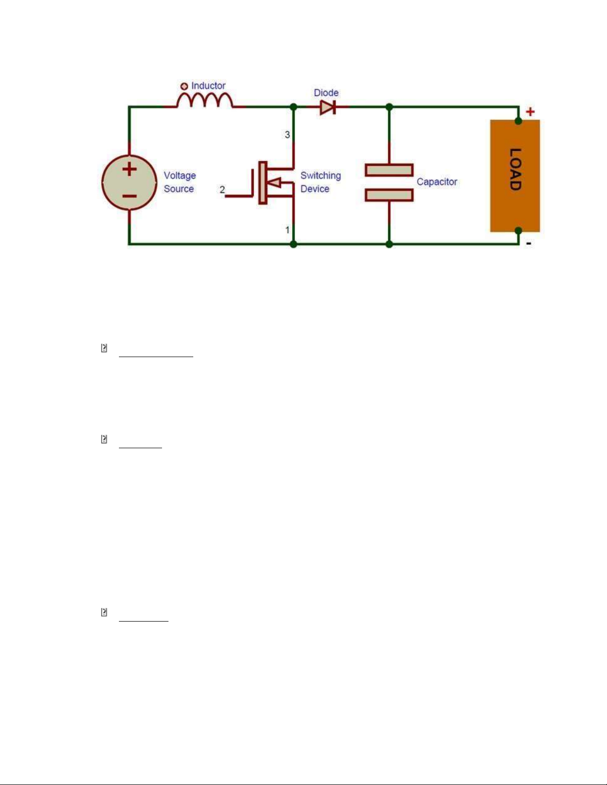
The efficiency of the bridge rectifier is higher than the efficiency of a half-wave rectifier 2.3. Boost converter
The above illustrates the basic circuit of a boost DC voltage converter. This circuit
consists of 4 basic electronic components that are inductor L, semiconductor switch S (can
be MOSFET, BJT or IGBT), diode D and capacitor C. Input DC voltage source is connected
to inductor. The MOSFET semiconductor device acts as a switch capable of opening and
closing it closes when the MOSFET is excited (a square wave is applied to the gate terminal
at high level) and opens when the MOSFET is not driven (a square wave is applied to the gate terminal at low level)
Figure 2.8: Boost converter circuit
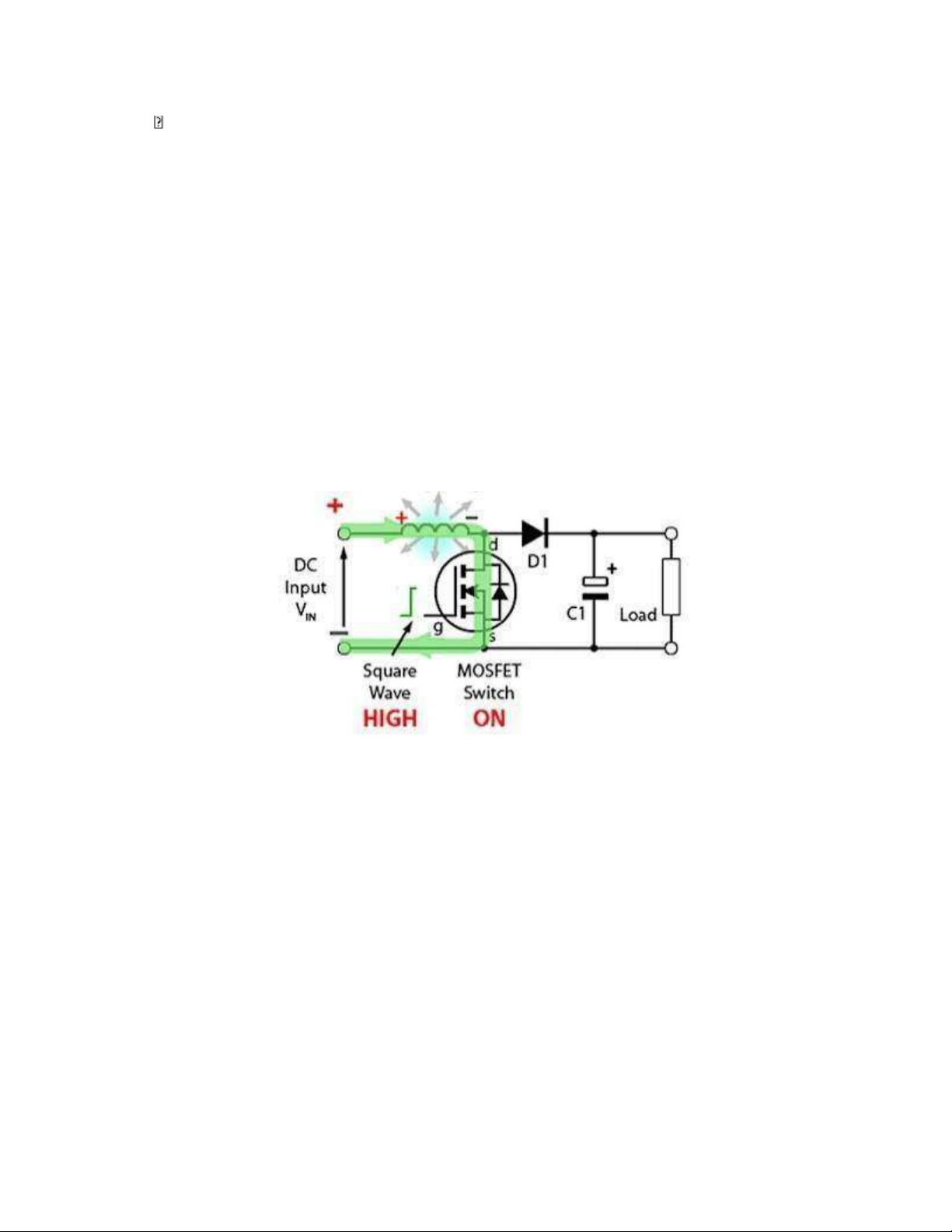
MOSFET Switch On
The MOSFET conducts electricity, causing the right end of the inductor L to be
connected to the negative terminal of the power supply. Therefore, a current will flow
between the positive and negative terminals of the power supply through the coil L and
gradually increase from some initial value. The coil accumulates energy in the form of a
magnetic field. Almost no current flows in the rest of the circuit because at this point diode
D1 breaks due to reverse bias and it will cut the load circuit from source E, current through
the load is maintained by capacitor C acting as source. lOMoARcPSD| 36086670
Figure 2.9: When MOSFET switch on
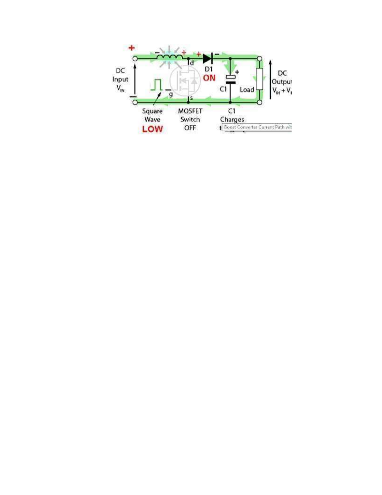
MOSFET Switch Off
The circuit is active at the time we let the MOSFET break, at this time on the coil L there
is an inductance voltage against the current reduction. The voltage polarity across the coil
L is in the opposite direction from the time the MOSFET conducts, allowing current to
flow. This results in two voltages, supply voltage VIN and voltage VL across the coil in series
with each other. This higher voltage (VIN + VL) forwards the diode D. The generated current
flows through D and charges the capacitor C to the value VIN + VL minus some voltage
across D, while providing for load.
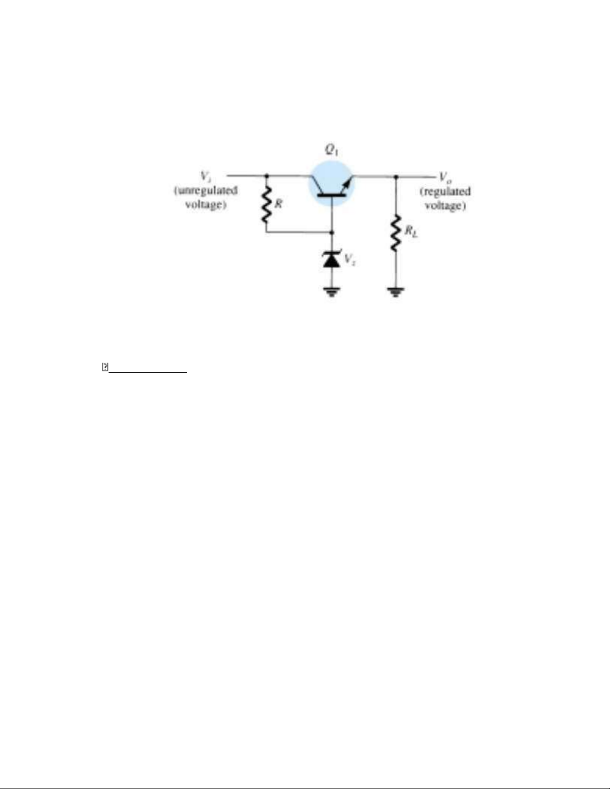
2.4. Voltage regulator circuit
In a power supply system, a regulator is an essential component, used to produce a
constant output voltage in power electronics. We need a voltage regulator that generates a
stable output for the variations in input voltage. There are different types of voltage
regulators like Zener, series, shunt, fixed positive, IC, adjustable, negative, dual tracking,
etc…Each type of circuit can provide an output dc voltage that is regulated or maintained
at a set value even if the input voltage varies or if the load connected to the output changes.
In this project, we use a series voltage regulator.
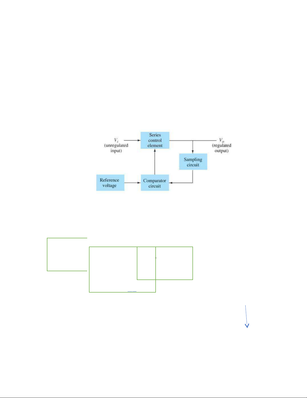
The basic connection of series regulator circuit is shown in the block diagram of
Figure.2.10. The series element controls the amount of the input voltage that gets to the lOMoARcPSD| 36086670
output. The output voltage is sampled by a circuit that provides a feedback voltage to be
compared to a reference voltage:
• If the output voltage increases, the comparator circuit provides a control signal to
cause the series control element to decrease the amount of the output voltagethereby
maintaining the output voltage.
• If the output voltage decreases, the comparator circuit provides a control signal to
cause the series control element to increase the amount of the output voltage thereby
maintaining the output voltage
Figure 2.10: Series regulator block diagram
CHAPTER 3: PRINCIPLE OF WORKING
3.1. Block diagram The piezoelec
The bridge rect ifier The boost material (sen c onverter lOMoARcPSD| 36086670 Electrical ener gy ge re The voltage consumption Battery char gulator circuit circuits
Figure 3.1: Block diagram of Footstep power generation
The figure 3.1 indicates the block diagram of a footstep power generation. This system
can be divided into several parts: The piezoelectric material (sensor), the full wave bridge,
boost converter, voltage regulator circuit and charge circuit.
The function of the piezoelectric material (sensor) is converts the pressure applied to it
into electrical energy. The source of pressure can be either from the weight of the moving
vehicles or from the weight of the people walking over it. Each object will generate different
energy levels and the output of the piezoelectric material is not a steady one. So, a bridge
circuit is used to convert this variable voltage into a linear one. The AC ripple filter is used
to filter out any other fluctuations in the output to obtain a smoother wave image.
The boost converter (step-up converter) is a DC-to-DC power converter that steps up
voltage (while stepping down current) from its input (supply) to its output (load).
The voltage regulator circuit is a circuit that has the function of generating or maintaining
a stable voltage even if the input changes over a wide range. We can simply understand that
the voltage stabilizer circuit always has a stable output voltage no matter how the input voltage changes.
The main function of the charging circuit is to store electrical energy to provide lighting,
automatically cut off when fully charged, short circuit protection, overload protection, overcurrent protection. lOMoARcPSD| 36086670
3.2. Principle of Footstep power generation
The piezoelectric material converts the pressure applied to it into electrical energy. The
source of pressure can be either from the weight of the moving vehicles or from the weight
of the people walking over it. As the power output from a single piezo film was extremely
low, combination of few Piezo films is investigated. Two possible connections were tested
- parallel and series connections. The parallel connection did not show significant increase
in the voltage output. With series connection, additional piezo-film results in increased of
voltage output but not in linear proportion. So here a combination of both parallel and series
connection is employed for producing voltage output with high current density. The current
produced by piezoelectric transducers is alternating in nature and hence cannot run, home
appliances. Thus, to make it a stable direct current, Fullbridge rectifier is commonly used
as rectifier circuits to convert the AC output of a piezoelectric into a DC voltage. The
rectifying circuits consist of 4 diodes. The produced electrical energy from piezoelectric
crystal is very low in the order of 3 volts and is stored in battery to charge controller, since
it is not possible to charge 6V battery through crystal output. To increase the voltage, the
boost converter circuit is used. The level of voltage ranges 6v and it is stored in 6v battery.
On the other hand, the output of the bridge rectifier consists of undulating ripples
superimposed on the DC voltage. By connecting a simple Zener diode at the output of the
rectifier circuit, we can get a more stable output DC voltage. With the charger we can store
energy as well as serve for lighting activities
CHAPTER 4: SIMULATION AND ANALYSIS
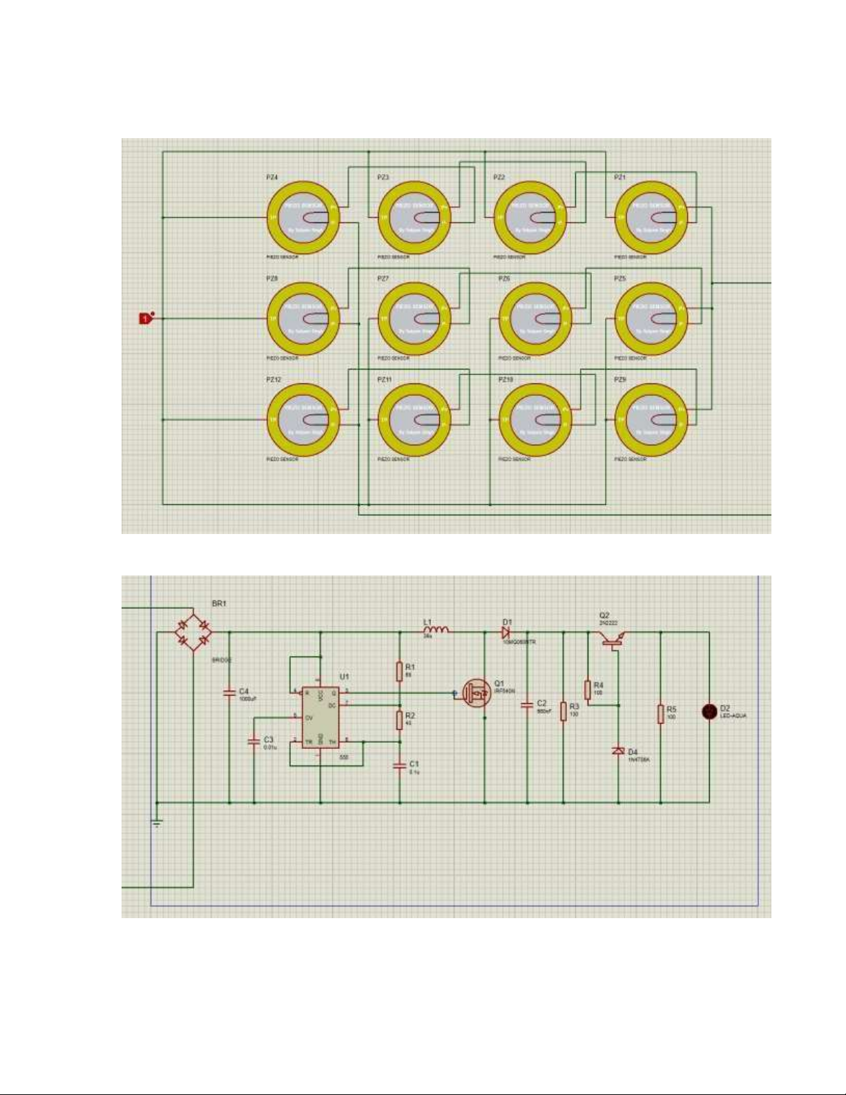
4.1. Boost converter
The figure 4.1 is the boost converter circuit. After we connect the Piezoelectric sensor
with full-wave bridge rectifier, we obtain direct current (DC), lOMoARcPSD| 36086670
Figure 4.1. Boost converter circuit - Calculate Requirements : Inductor Choose Capacitor
The maximum voltage that the capacitor can operate must be bigger than voltage output. lOMoARcPSD| 36086670
Choose maximum voltage that the capacitor can operate: 100 (V) Diode Schottky
The maximum voltage that the diode can operate must be bigger than voltage output.
Choose diode which , maximum voltage that the capacitor can operate: 60 (V)
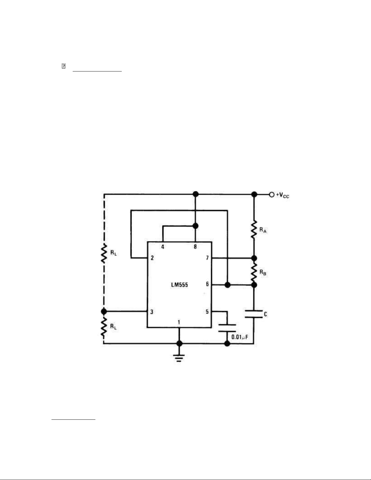
4.2. Oscillating circuit
In the oscillating circuit, we use IC 555. According Texas Instrument’s company, we obtain the circuit.
Figure 4.2: IC 555 Requirements: We choose lOMoARcPSD| 36086670 We choose
4.3. Series regulator circuit
Figure 4.3: Series regulator circuit Requirements:
Before connect series regulator circuit . When connect series regulator circuit Choose lOMoARcPSD| 36086670 4.4. Simulation
Figure 4.4: Connection of Piezoelectric sensor lOMoARcPSD| 36086670
Figure 4.5: Simulation circuit
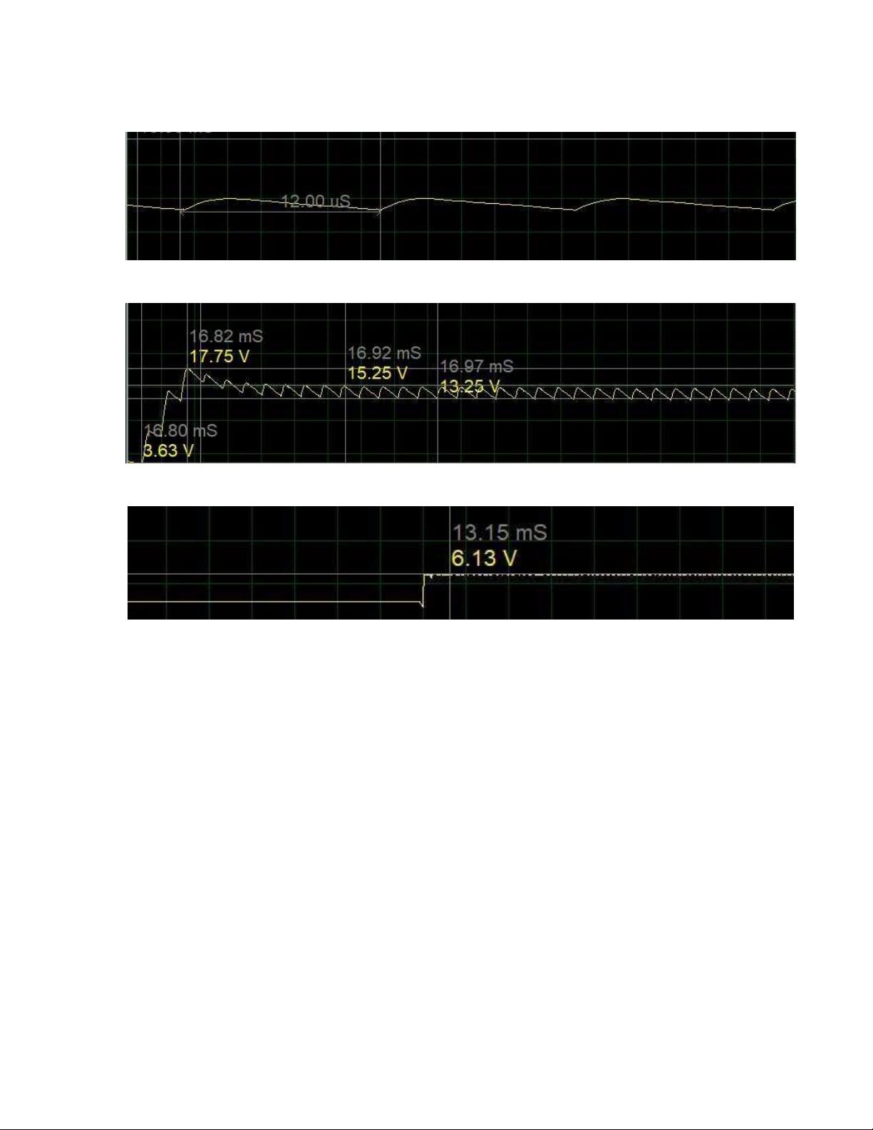
Figure 4.6: The time period
Figure 4.7: The voltage after boost
Figure 4.8: The voltage after regulator
CHAPTER 5: RESULT AND CONCLUSION
According to the simulation circuit, we can see that depending on the gravity acting on
the sensor, it is possible to change a different voltage level, but this voltage is extremely
small, so a booster and voltage stabilizer circuit is needed to can be charged to a storage
battery and provide electricity for lighting operations
In the conclusion of our project, it can be seen that this is an extremely potential energy
source because of its availability and environmental friendliness. On the other hand taking
advantage of wasted kinetic energy to convert into electricity provides a large amount of
electrical energy that needs to be promoted on a large scale. It is especially suited for
implementation in crowded areas. This can be used in street lighting without use of long
power lines. It can also be used as charging ports, lighting of pavement side buildings. lOMoARcPSD| 36086670 Advantage:
• Power generation is simply walking or running. • No need fuel input.
• Considered as available, clean energy and friendly with environment
• Energy saving and easy maintenance
• Battery is used to store the generated power. Disadvantage:
• Only applicable for the particular place.
• Initial cost of this arrangement is high.
• Mechanical moving part is high.
• Care should be taken for batteries. REFERENCE
1. Robert Boylestad – Louis Nashelsky (1998), Electronic devices and circuit theory
(seven edition), Prentice Hall
2. Kiran Boby – Aleena Paul.K – Anumol.C.V – Josnie Ann Thomas – Nimisha.K.K
(2014), Footstep Power Generation Using Piezoelectric Transducers, International
Journal of Engineering and Innovative Technology (IJEIT)
3. Brigitte Hauke (2014), Basic Calculation of a Boost Converter’s Power stage, Texas Instruments
4. Ali Khattak (2017), Footstep Power Generation System, International Journal of
Innovations in Engineering and Science (IJIES)
5. Anis Maisarah Mohd Asry - Farahiyah Mustafa - Sy Yi Sim - Maizul Isak -
Aznizam Mohamad (2019), Study on Footstep power generation using lOMoARcPSD| 36086670
Piezoelectric, Indonesian Journal of Electrical Engineering and Computer Science (IJEECS)
6. Nanomotion, The Piezoelectric Effect,
https://www.nanomotion.com/nanomotiontechnology/piezoelectric-effect/, date accessed: 15/12/2021
7. BYJU’S, Bridge Rectifier, https://byjus.com/physics/bridge-rectifier/, date accessed: 10/12/2021
8. Wikipedia, Piezoelectric sensor,
https://en.wikipedia.org/wiki/Piezoelectric_sensor, date accessed: 15/12/2021
9. Avnet Abacus, Pressure Sensor: The Design Engineer’s Guide,
https://www.avnet.com/wps/portal/abacus/solutions/technologies/sensors/pressures
ensors/core-technologies/piezoelectric/, date accessed: 16/12/2021
10.Texas Instruments (2015), LM555 Timer

