Tóm tắt về Các quy trình đúc kim loại môn Công nghệ đúc | Trường Đại học Công nghệ Thông tin, Đại học Quốc gia Thành phố Hồ Chí Minh
Tóm tắt về Các quy trình đúc kim loại môn Công nghệ đúc | Trường Đại học Công nghệ Thông tin, Đại học Quốc gia Thành phố Hồ Chí Minh. Tài liệu được sưu tầm giúp bạn tham khảo, ôn tập và đạt kết quả cao. Mời bạn đọc đón xem.
Môn: Công nghệ 15 tài liệu
Trường: Trường Đại học Công nghệ Thông tin, Đại học Quốc gia Thành phố Hồ Chí Minh 666 tài liệu
Tác giả:


Preview text:
ME 222 Manufacturing Technology - I (3-0-0-6)
Introduction to manufacturing processes
Casting processes: Moulding materials and their requirements; Patterns:
Types and various pattern materials. Various casting methods, viz., sand
casting investment casting, pressure die casting, centrifugal casting,
continuous casting, thin roll casting; Mould design; Casting defects and their remedies. (14 classes)
Metal forming processes: Various metal forming techniques and their
analysis, viz., forging, rolling, extrusion, wire drawing, sheet metal
working, spinning, swaging, thread rolling; Super plastic deformation;
Metal forming defects. (14 classes)
Metal joining processes: brazing, soldering, welding; Solid state welding
methods; resistance welding; arc welding; submerged arc welding; inert
gas welding; Welding defects, inspection. (9 classes)
Powder metallurgy & its applications (3 classes) R.Ganesh Narayanan, IITG Texts:
1. A Ghosh and A K Mallik, Manufacturing Science, Wiley Eastern, 1986.
2. P Rao, Manufacturing Technology: Foundry, Forming And Welding, Tata McGraw Hill, 2008.
3. M.P. Groover, Introduction to manufacturing processes, John Wiley & Sons, 2012
4. Prashant P Date, Introduction to manufacturing technologies Principles and
technologies, Jaico publications, 2010 (new book) References:
1. J S Campbell, Principles Of Manufacturing Materials And Processes, Tata McGraw Hill, 1995.
2. P C Pandey and C K Singh, Production Engineering Sciences, Standard Publishers Ltd., 2003.
3. S Kalpakjian and S R Schmid, Manufacturing Processes for Engineering
Materials, Pearson education, 2009.
4. E. Paul Degarmo, J T Black, Ronald A Kohser, Materials and processes in
manufacturing, John wiley and sons, 8th edition, 1999
Tentative grading pattern:
QUIZ 1: 10; QUIZ 2: 15; MID R.Ganesh SEM: Naray 30; anan, IITG END SEM: 45; ASSIGNMENT: 10 Metal casting processes
• Casting is one of the oldest manufacturing process. It is the first step
in making most of the products. • Steps: - Making mould cavity
- Material is first liquefied by properly heating it in a suitable furnace.
- Liquid is poured into a prepared mould cavity - allowed to solidify
- product is taken out of the mould cavity, trimmed and made to shape
We should concentrate on the following for successful casting operation:
(i)Preparation of moulds of patterns
(ii)Melting and pouring of the liquefied metal
(iii)Solidification and further cooling to room temperature (iv)Defects and inspection R.Ganesh Narayanan, IITG Advantages
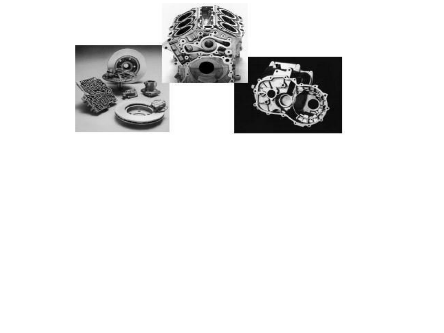
• Molten material can flow into very small sections so that intricate shapes can
be made by this process. As a result, many other operations, such as
machining, forging, and welding, can be minimized.
• Possible to cast practically any material: ferrous or non-ferrous.
• The necessary tools required for casting moulds are very simple and
inexpensive. As a result, for production of a small lot, it is the ideal process.
• There are certain parts (like turbine blades) made from metals and alloys that
can only be processed this way. Turbine blades: Fully casting + last machining.
• Size and weight of the product is not a limitation for the casting process. NPTEL R.Ganesh course o Nar n a Mayan nufan a , II ctu T riG
n g processes – I, Pradeep Kumar et al. Limitations
• Dimensional accuracy and surface finish of the castings made by
sand casting processes are a limitation to this technique.
• Many new casting processes have been developed which can take
into consideration the aspects of dimensional accuracy and surface
finish. Some of these processes are die casting process, investment
casting process, vacuum-sealed moulding process, and shell moulding process.
• Metal casting is a labour intensive process • Automation: a question R.Ganesh Narayanan, IITG
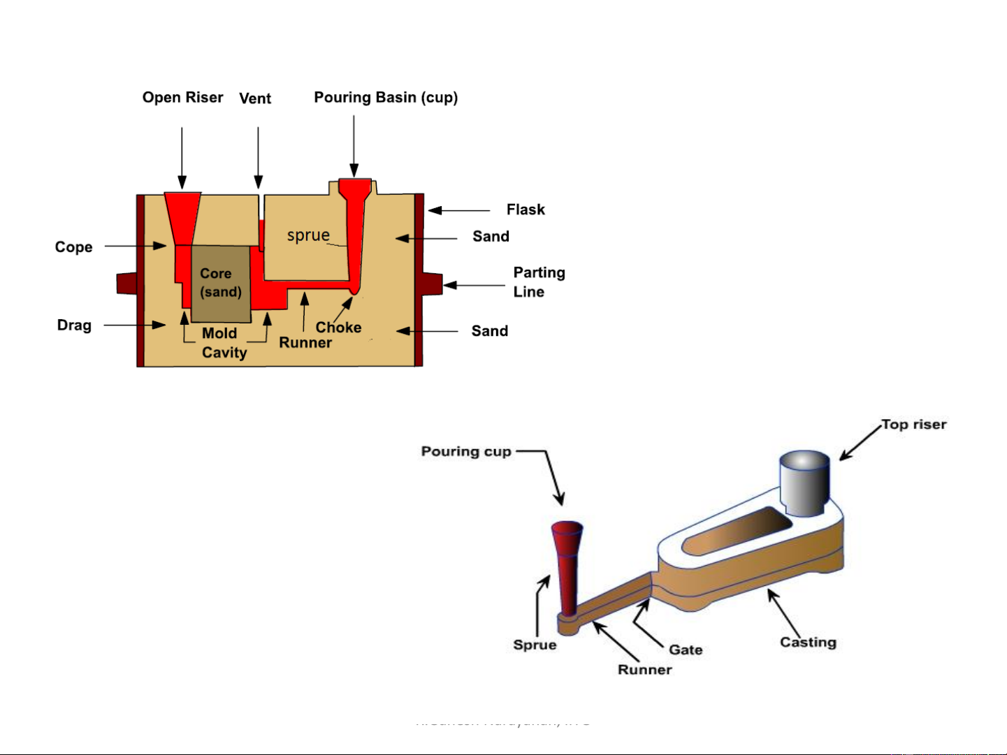
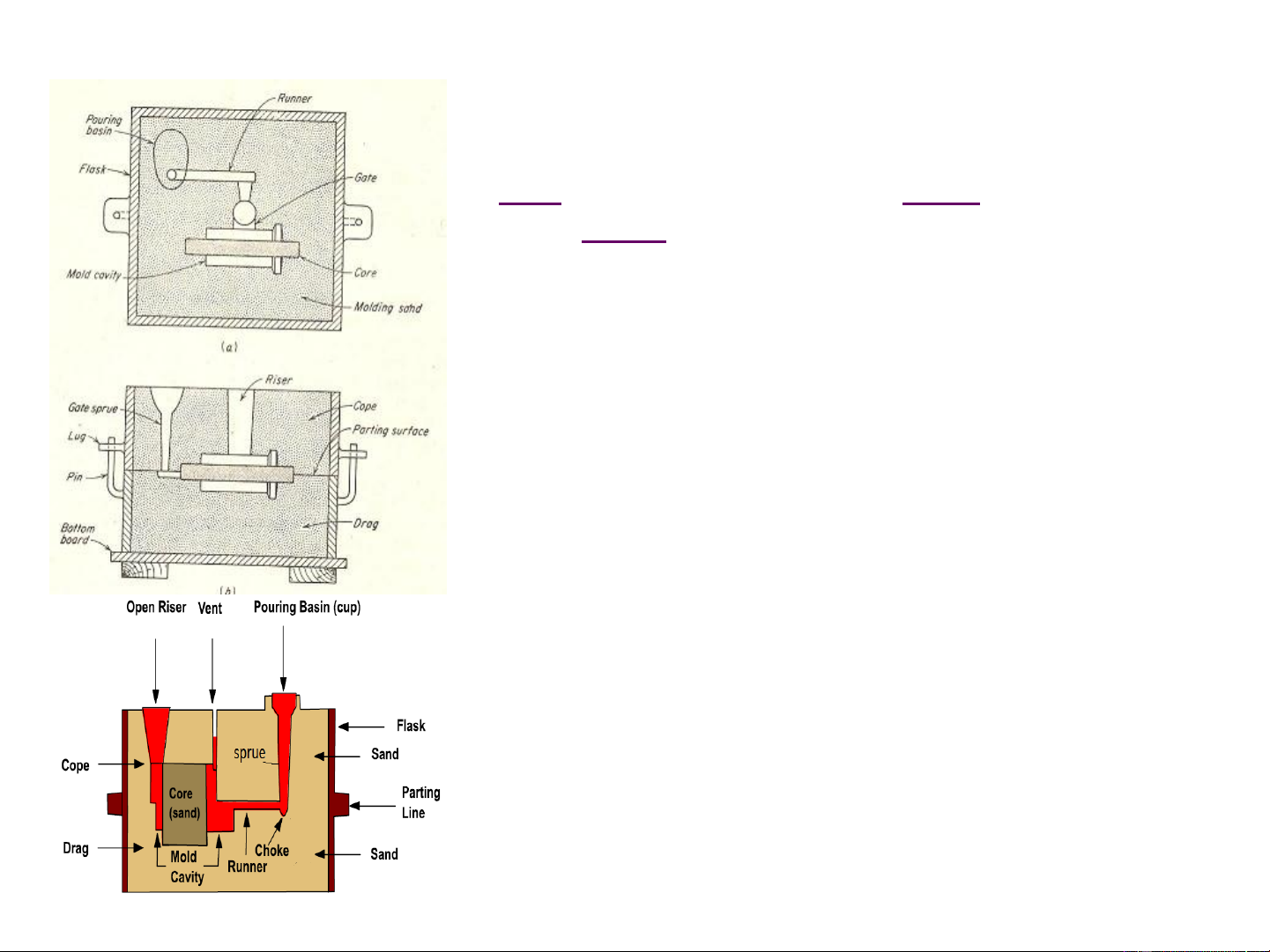
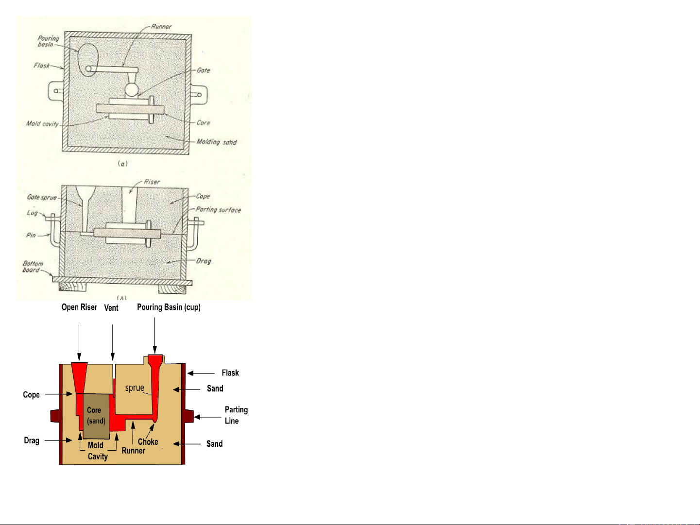
NPTEL course on Manufacturing processes – I, Pradeep Kumar et al. Typical sand mould
Mould Section and casting nomenclature
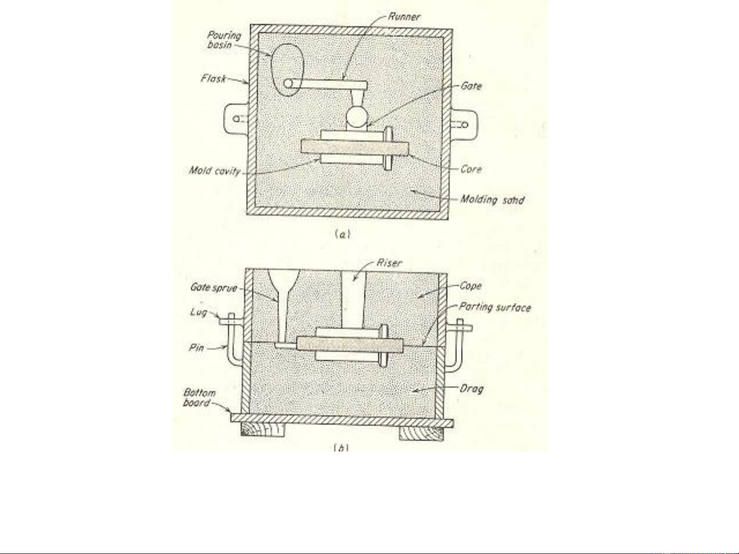
NPTEL course on Manufacturing processes – I, Pradeep Kumar et al. R.Ganesh patt Nar ern ayan att an, achIITG
ed with gating and risering system
Mould Section and casting nomenclature, (a) top view, (b) front view R.Ganesh Nar J S ay Ca an mpan b , e II ll T , G P
rinciples Of Manufacturing Materials And Processes
Important casting terms Flask: A metal or wood frame, without fixed top or
bottom, in which the mould is formed. Depending
upon the position of the flask in the moulding
structure, it is referred to by various names such as
drag – lower moulding flask, cope – upper moulding
flask, cheek – intermediate moulding flask used in three piece moulding.
Pattern: It is the replica of the final object to be made.
The mould cavity is made with the help of pattern.
Parting line: This is the dividing line between the two
moulding flasks that makes up the mould.
Moulding sand: Sand, which binds strongly without
losing its permeability to air or gases. It is a mixture of
silica sand, clay, and moisture in appropriate proportions.
Facing sand: The small amount of carbonaceous
material sprinkled on the inner surface of the mould
cavity to give a better surface finish to the castings. R.Ganesh Nar J S ay Ca an mpan b , e II ll T , G P
rinciples Of Manufacturing Materials And Processes
NPTEL course on Manufacturing processes – I, Pradeep Kumar et al.
Core: A separate part of the mould, made of sand and
generally baked, which is used to create openings and
various shaped cavities in the castings.
Pouring basin: A small funnel shaped cavity at the top of the
mould into which the molten metal is poured.
Sprue: The passage through which the molten metal, from
the pouring basin, reaches the mould cavity. In many cases
it controls the flow of metal into the mould.
Runner: The channel through which the molten metal is
carried from the sprue to the gate.
Gate: A channel through which the molten metal enters the mould cavity.
Chaplets: Chaplets are used to support the cores inside the
mould cavity to take care of its own weight and overcome the metallostatic force.
Riser: A column of molten metal placed in the mould to feed
the castings as it shrinks and solidifies. Also known as “feed head”.
Vent: Small opening in the mould to facilitate escape of air R.Ganesh Narayanan, IITG and gases. Steps in making sand castings
The six basic steps in making sand castings are,
(i) Pattern making, (ii) Core making, (iii) Moulding, (iv) Melting and pouring, (v) Cleaning Pattern making
- Pattern: Replica of the part to be cast and is used to prepare the
mould cavity. It is the physical model of the casting used to make the
mould. Made of either wood or metal.
-The mould is made by packing some readily formed aggregate
material, such as moulding sand, surrounding the pattern. When the
pattern is withdrawn, its imprint provides the mould cavity. This cavity
is filled with metal to become the casting.
- If the casting is to be hollow, additional patterns called ‘cores’, are used to form these cavities. R.Ganesh Narayanan, IITG Core making
Cores are placed into a mould cavity to form the interior surfaces of
castings. Thus the void space is filled with molten metal and eventually becomes the casting. Moulding
Moulding is nothing but the mould preparation activities for receiving molten metal.
Moulding usually involves: (i) preparing the consolidated sand mould around
a pattern held within a supporting metal frame, (ii) removing the pattern to
leave the mould cavity with cores.
Mould cavity is the primary cavity.
The mould cavity contains the liquid metal and it acts as a negative of the desired product.
The mould also contains secondary cavities for pouring and channeling
the liquid material in to the primary cavity and will act a reservoir, if required. R.Ganesh Narayanan, IITG Melting and Pouring
The preparation of molten metal for casting is referred to simply as
melting. The molten metal is transferred to the pouring area where the moulds are filled. Cleaning
Cleaning involves removal of sand, scale, and excess metal from
the casting. Burned-on sand and scale are removed to improved the
surface appearance of the casting. Excess metal, in the form of fins,
wires, parting line fins, and gates, is removed. Inspection of the
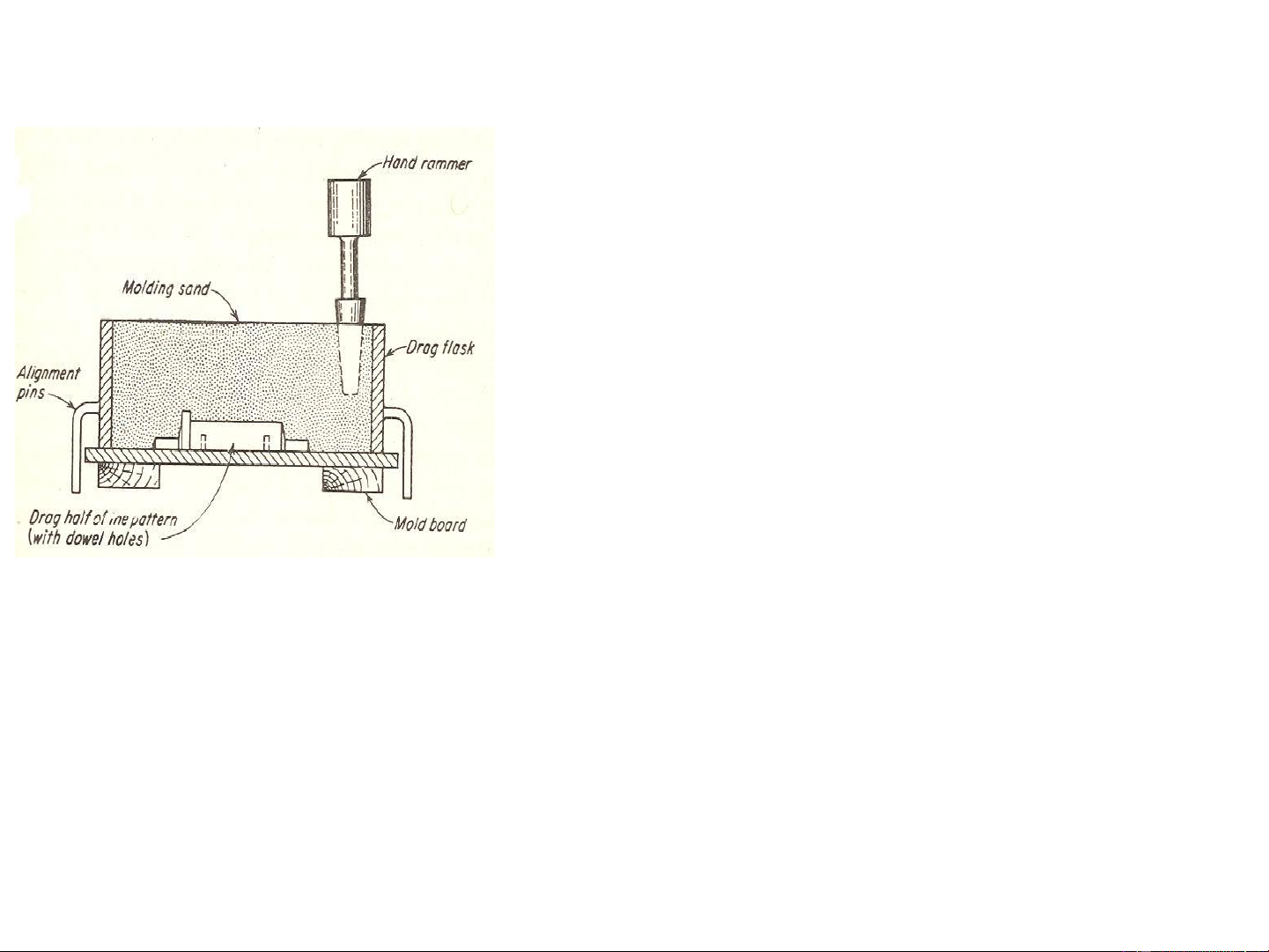
casting for defects and general quality is performed. R.Ganesh Narayanan, IITG Making a simple sand mould
1) The drag flask is placed on the board
2) Dry facing sand is sprinkled over the board
3) Drag half of the pattern is located on the mould
board. Dry facing sand will provide a non-sticky layer.
4) Molding sand is then poured in to cover the
pattern with the fingers and then the drag is filled completely
5) Sand is then tightly packed in the drag by
means of hand rammers. Peen hammers (used
first close to drag pattern) and butt hammers
(used for surface ramming) are used.
6) The ramming must be proper i.e. it must neither be too hard or soft. Too soft ramming
will generate weak mould and imprint of the pattern will not be good. Too hard
ramming will not allow gases/air to escape and hence bubbles are created in casting
resulting in defects called ‘blows’. Moreover, the making of runners and gates will be difficult.
7) After the ramming is finished, the excess sand is leveled/removed with a straight bar known as strike rod. R.Ganesh Narayanan, IITG
8) Vent holes are made in the drag to the full
depth of the flask as well as to the pattern
to facilitate the removal of gases during
pouring and solidification. Done by vent rod.
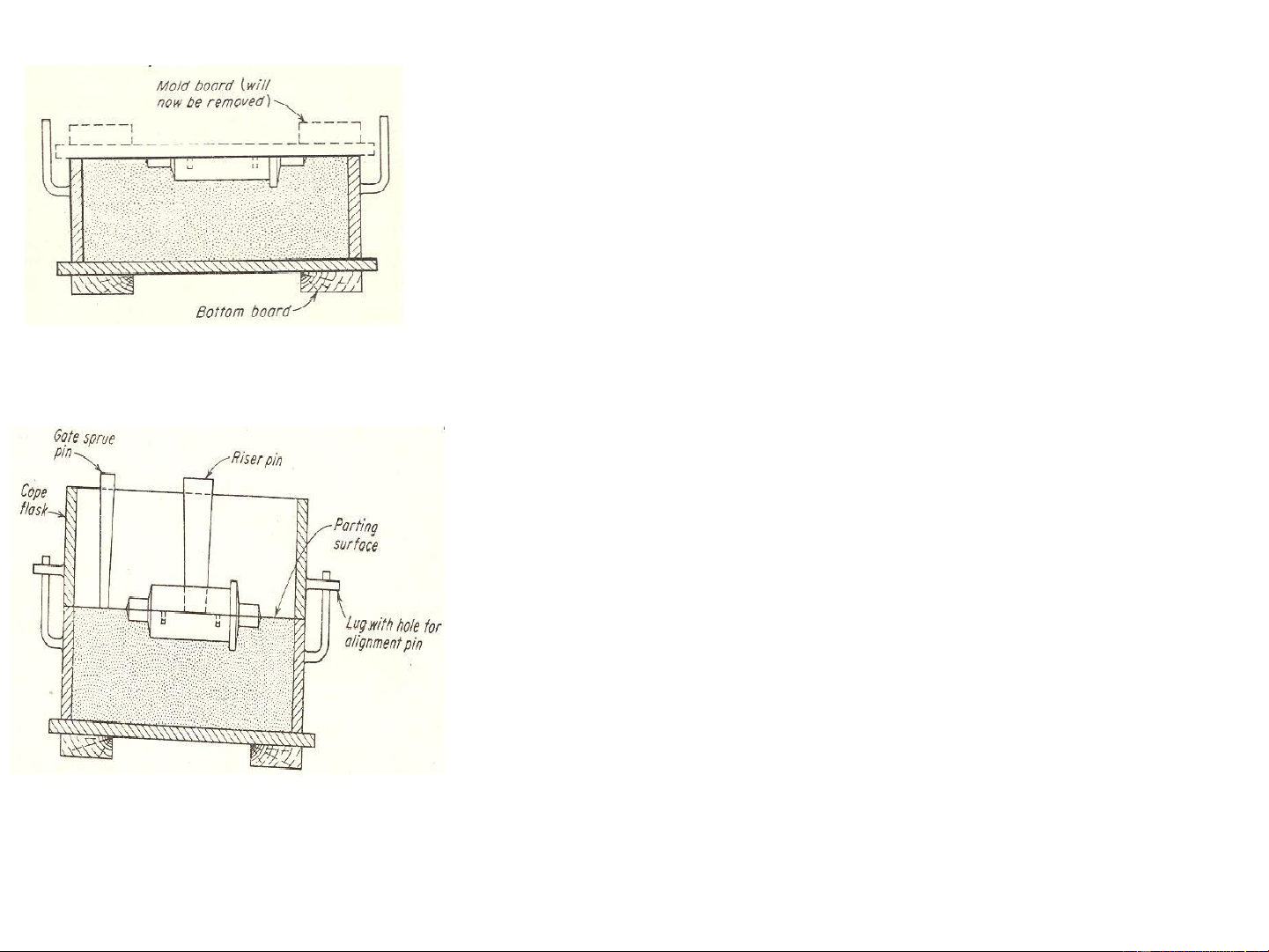
9) The finished drag flask is now made
upside down exposing the pattern.
10) Cope half of the pattern is then placed
on the drag pattern using locating pins. The
cope flask is also located with the help of
pins. The dry parting sand is sprinkled all
over the drag surface and on the pattern.
11) A sprue pin for making the sprue
passage is located at some distance from
the pattern edge. Riser pin is placed at an appropriate place.
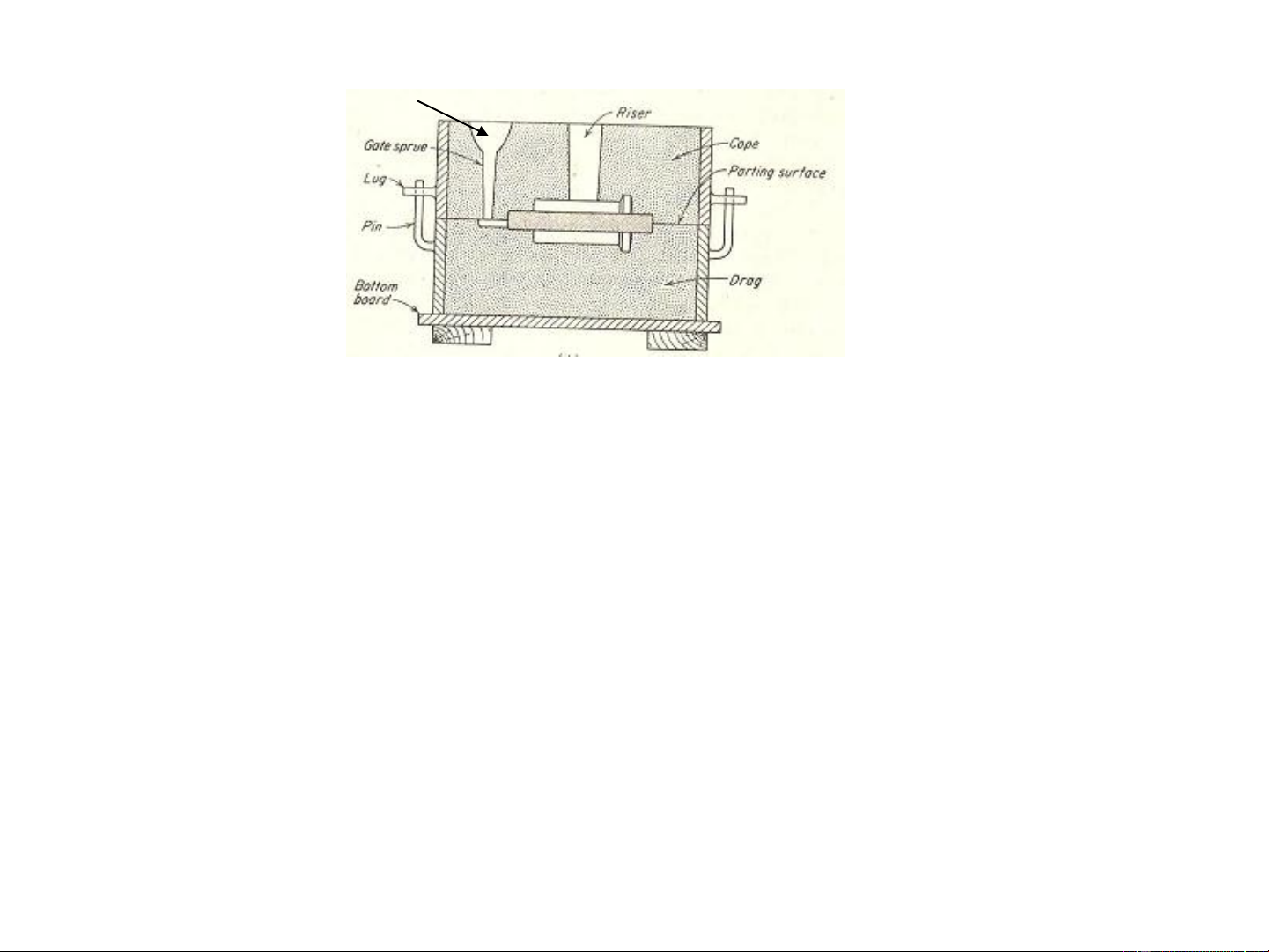
12) Filling, ramming and venting of the cope is done in the same manner. R.Ganesh Narayanan, IITG Pour basin
13) The sprue and riser are removed and a pouring basin is made at
the top to pour the liquid metal.
14) Pattern from the cope and drag is removed.
15) Runners and gates are made by cutting the parting surface with a
gate cutter. A gate cutter is a piece of sheet metal bent to the desired radius.
16) The core for making a central hole is now placed into the mould
cavity in the drag. Rests in core prints.
17) Mould is now assembled and ready for pouring. R.Ganesh Narayanan, IITG Pattern
The pattern and the part to be made are not same. They differ in the following aspects.
1.A pattern is always made larger than the final part to be made. The
excess dimension is known as Pattern allowance.
Pattern allowance => shrinkage allowance, machining allowance
2.Shrinkage allowance: will take care of contractions of a casting
which occurs as the metal cools to room temperature.
Liquid Shrinkage: Reduction in volume when the metal changes
from liquid state to solid state. Riser which feed the liquid metal to the
casting is provided in the mould to compensate for this.
Solid Shrinkage: Reduction in volume caused when metal looses
temperature in solid state. Shrinkage allowance is provided on the patterns to account for this.
Shrink rule is used to compensate solid shrinkage depending on the R.Ganesh Narayanan, IITG material contraction rate.
Cast iron: One foot (=12 inches) on the 1/8-in-per-foot shrink rule actually measures 12-1/8 inches.
So, 4 inch will be 4-1/24 inch for considering shrinkage allowance. Shrink rule for other Shrinkage allowance Material Dimension materials (inch/ft) Grey Cast Iron Up to 2 feet 0.125 2 feet to 4 feet 0.105 over 4 feet 0.083 Cast Steel Up to 2 feet 0.251 2 feet to 6 feet 0.191 over 6 feet 0.155 Aluminum Up to 4 feet 0.155 4 feet to 6 feet 0.143 over 6 feet 0.125 Magnesium Up to 4 feet 0.173 R.Ganesh Narayanan, IITG Ov er 4 feet 0.155
2. The shrinkage allowance depends on the coefficient of
thermal expansion of the material (α). A simple relation
indicates that higher the value of α, more is the shrinkage allowance.
3. For a dimension ‘l’, shrinkage allowance is αl (θf –θ0). Here
θf is the freezing temperature and θ is the room 0 temperature.
4. Machining allowance: will take care of the extra material
that will be removed to obtain a finished product. In this the
rough surface in the cast product will be removed. The
machining allowance depends on the size of the casting,
material properties, material distortion, finishing accuracy and machining method. R.Ganesh Narayanan, IITG
A Ghosh and A K Mallik, Manufacturing Science
Machining allowances of various metals Metal Dimension (inch) Allowance (inch) Up to 12 0.12 Cast iron 12 to 20 0.20 20 to 40 0.25 Up to 6 0.12 Cast steel 6 to 20 0.25 20 to 40 0.30 Up to 8 0.09 Non ferrous 8 to 12 0.12 12 to 40 0.16 R.Ganesh Narayanan, IITG 5. Draft allowance:
All the surfaces parallel to the direction in which the pattern will be
removed are tapered slightly inward to facilitate safe removal of the
pattern. This is called ‘draft allowance’. General usage:
External surfaces ; Internal surfaces, holes, pockets Typical Draft Pattern Height of the Draft angle Draft angle Allowances material given surface (External (Internal (inch) surface) surface) 1 3.00 3.00 1 to 2 1.50 2.50 Wood 2 to 4 1.00 1.50 4 to 8 0.75 1.00 8 to 32 0.50 1.00 1 1.50 3.00 1 to 2 1.00 2.00 Metal and 2 to 4 0.75 1.00 plastic 4 to 8 0.50 1.00 8 to 32 0.50 0.75 R.Ganesh Narayanan, IITG
Tài liệu liên quan:
-

Bài giảng Chương 1: Tổng quan về cơ sở dữ liệu | Trường Đại học Công nghệ Thông tin, Đại học Quốc gia Thành phố Hồ Chí Minh
49 25 -

Hướng dẫn sử dụng MARS – chương trình mô phỏng hợp ngữ (assembly) MIPS | Trường Đại học công nghệ thông tin, Đại học Quốc gia thành phố Hồ Chí Minh
31 16 -

Bài giảng Phụ thuộc hàm và dạng chuẩn môn Cơ sở dữ liệu | Trường Đại học Công nghệ Thông tin, Đại học Quốc gia Thành phố Hồ Chí Minh
36 18 -
BC THOlap - Xây Dựng Kho Dữ Liệu Quản Lý Công Ty Tour Du Lịch. Môn Công nghệ | Đại học Trường Đại học Công nghệ thông tin, Đại học Quốc gia Thành phố Hồ Chí Minh
96 48