Unspecific Hardware Configuration S7-1200 | Môn Applied Machine Learning - Đại học Sư phạm Kỹ thuật Thành phố Hồ Chí Minh
The SCE training curriculum for the integrated automation solution Totally Integrated Automation (TIA) was prepared for the program "Siemens Automation Cooperates with Education (SCE)" specifically for training purposes for public educational facilities and R&D institutions. Siemens AG does not guarantee the contents. Tài liệu được sưu tầm gồm 39 trang, giúp bạn ôn tập tốt hơn. Mời các bạn đón xem.
Môn: Applied Machine Learning (APML436564) 10 tài liệu
Trường: Trường Đại học Sư phạm Kỹ thuật Thành phố Hồ Chí Minh 4.4 K tài liệu
Tác giả:


Preview text:
lOMoAR cPSD| 58605085
SCE Training Curriculum
Siemens Automation Cooperates with Education | 02/2016 TIA Portal Module 011-100
Unspecified Hardware Configuration with SIMATIC S7-1200
For unrestricted use in educational and R&D institutions. © Siemens AG 2016. All rights reserved.
SCE Training Curriculum | TIA Portal Module 011-100, Edition 02/2016 | Digital Factory, DF FA
Matching SCE Trainer Packages for these training curriculums
• SIMATIC S7-1200 AC/DC/RELAY (set of 6) "TIA Portal" Order no.: 6ES7214-1BE30-4AB3
• SIMATIC S7-1200 DC/DC/DC (set of 6) "TIA Portal" Order no.: 6ES7214-1AE30-4AB3 lOMoAR cPSD| 58605085
• Upgrade SIMATIC STEP 7 BASIC V13 SP1 (for S7-1200)
(set of 6) "TIA Portal" Order no.: 6ES7822-0AA03-4YE5
Note that these trainer packages are replaced with successor packages when necessary.
An overview of the currently available SCE packages is available at: siemens.com/sce/tp Continued training
For regional Siemens SCE continued training, get in touch with your regional SCE contact siemens.com/sce/contact
Additional information regarding SCE siemens.com/sce
Information regarding use
The SCE training curriculum for the integrated automation solution Totally Integrated Automation (TIA) was
prepared for the program "Siemens Automation Cooperates with Education (SCE)" specifically for training
purposes for public educational facilities and R&D institutions. Siemens AG does not guarantee the contents.
This document is to be used only for initial training on Siemens products/systems, which means it can be
copied in whole or part and given to those being trained for use within the scope of their training. Circulation
or copying this training curriculum and sharing its content is permitted within public training and advanced
training facilities for training purposes.
Exceptions require written consent from the Siemens AG contact person: Roland Scheuerer roland.scheuerer@siemens.com.
Offenders wil be held liable. Al rights including translation are reserved, particularly if a patent is granted or
a utility model or design is registered.
Use for industrial customer courses is explicitly not permitted. We do not consent to commercial use of the training curriculums.
We wish to thank the TU Dresden, particularly Prof. Dr.-Ing. Leon Urbas and Dipl.-Ing. Annett Pfeffer, the
Michael Dzial as Engineering Corporation and al other involved persons for their support during the
preparation of this training curriculum.
For unrestricted use in educational and R&D institutions. © Siemens AG 2016. All rights reserved. 2
4d03884cfcdbd88b7f012887963793f1.docx Table of contents
1 Goal ...................................................................................................................................................................... 4
2 Prerequisite .......................................................................................................................................................... 4
3 Theory .................................................................................................................................................................. 4
3.1 SIMATIC S7-1200 automation system .......................................................................................................... 4 lOMoAR cPSD| 58605085
SCE Training Curriculum | TIA Portal Module 011-100, Edition 02/2016 | Digital Factory, DF FA
3.1.1 Range of modules .................................................................................................................................. 5
3.2 Operator control and display elements of the CPU 1214C DC/DC/DC ......................................................... 7
3.2.1 Front view of the CPU 1214C DC/DC/DC .............................................................................................. 7
3.2.2 SIMATIC memory card (MC) .................................................................................................................. 7
3.2.3 Operating states of the CPU .................................................................................................................. 8
3.2.4 Status and error displays........................................................................................................................ 8
3.3 STEP 7 Basic V13 (TIA Portal V13) programming software ......................................................................... 9
3.3.1 Project .................................................................................................................................................... 9
3.3.2 Hardware configuration .......................................................................................................................... 9
3.3.3 Planning the hardware ......................................................................................................................... 10
3.3.4 TIA Portal – Project view and portal view ............................................................................................. 11
3.3.5 Basic settings for the TIA Portal ........................................................................................................... 12
3.3.6 Set the IP address on the programming device ................................................................................... 14
3.3.7 Set the IP address in the CPU ............................................................................................................. 16
3.3.8 Restore the factory settings of the CPU ............................................................................................... 18
4 Task .................................................................................................................................................................... 19
5 Planning .............................................................................................................................................................. 20
6 Structured step-by-step instructions ................................................................................................................... 20
6.1 Create a new project ................................................................................................................................... 20
6.2 Read the hardware of SIMATIC S7-1200 .................................................................................................... 21
6.3 Configure the Ethernet interface of the CPU 1214C ................................................................................... 28
6.4 Configure the address areas ....................................................................................................................... 30
6.5 Save and compile the hardware configuration ............................................................................................ 30
6.6 Download the hardware configuration to the device ................................................................................... 31
6.7 Archive the project ....................................................................................................................................... 37
6.8 Checklist ...................................................................................................................................................... 38
7 Additional information ......................................................................................................................................... 39 lOMoAR cPSD| 58605085
SCE Training Curriculum | TIA Portal Module 011-100, Edition 02/2016 | Digital Factory, DF FA
UNSPECIFIED HARDWARE CONFIGURATION
– FOR A SIMATIC S7-1200 1 Goal
In this chapter, you wil first learn how to create a project. Next you wil be shown how you can use
the TIA Portal to detect hardware already installed and add it to a project. This hardware will then be configured. 2 Prerequisite
You do not need any previous knowledge from other chapters to successfully complete this
chapter. You only need an S7-1200 controller and a PC with the STEP 7 Basic V13 (TIA Portal V13) software. 3 Theory
3.1 SIMATIC S7-1200 automation system
The SIMATIC S7-1200 automation system is a modular microcontroller system for the lower performance range.
A comprehensive range of modules is available to optimally adapt the system to the automation task.
The S7 controller consists of a power supply and a CPU with integrated inputs and outputs or
additional input and output modules for digital and analog signals.
If necessary, communication processors and function modules are also used for special tasks such as stepper motor control.
The programmable logic controller (PLC) uses the S7 program to monitor and control a machine or
process. In doing so, the I/O modules are scanned in the S7 program using input addresses (%I)
and addressed using output addresses (%Q).
The system is programmed with the TIA Portal Basic or Professional software. lOMoAR cPSD| 58605085
SCE Training Curriculum | TIA Portal Module 011-100, Edition 02/2016 | Digital Factory, DF FA
3.1.1 Range of modules
The SIMATIC S7-1200 is a modular automation system and offers the fol owing range of modules:
Central processing units (CPUs) with different performance, integrated inputs/outputs, and
PROFINET interface (e.g. CPU 1214C)
Power supply module (PM) with input 120/230 V AC, 50 Hz / 60 Hz, 1.2 A / 0.7 A and output 24 V DC / 2.5 A
Signal boards (SBs) for adding analog or digital inputs/outputs, in which case the size of the CPU
remains unchanged. (Signal boards can be used with CPUs 1211C / 1212C and 1214C.)
Signal modules (SMs) for digital and analog inputs and outputs (a maximum of 2 SMs can be used
for CPU 1212C and a maximum of 8 SMs for CPU 1214C.) lOMoAR cPSD| 58605085
SCE Training Curriculum | TIA Portal Module 011-100, Edition 02/2016 | Digital Factory, DF FA
Communication modules (CMs) for serial communication RS232 / RS 485
(Up to 3 CMs can be used for CPUs 1211C / 1212C and 1214C.)
Compact switch module (CSM) with 4x RJ45 sockets 10/100 Mbps
SIMATIC memory cards from 2 MB to 32 MB for storing program data and for easy exchange of CPUs during maintenance.
Note: Only a single CPU (any type) with integrated digital inputs and digital outputs is
needed for this module. lOMoAR cPSD| 58605085
SCE Training Curriculum | TIA Portal Module 011-100, Edition 02/2016 | Digital Factory, DF FA
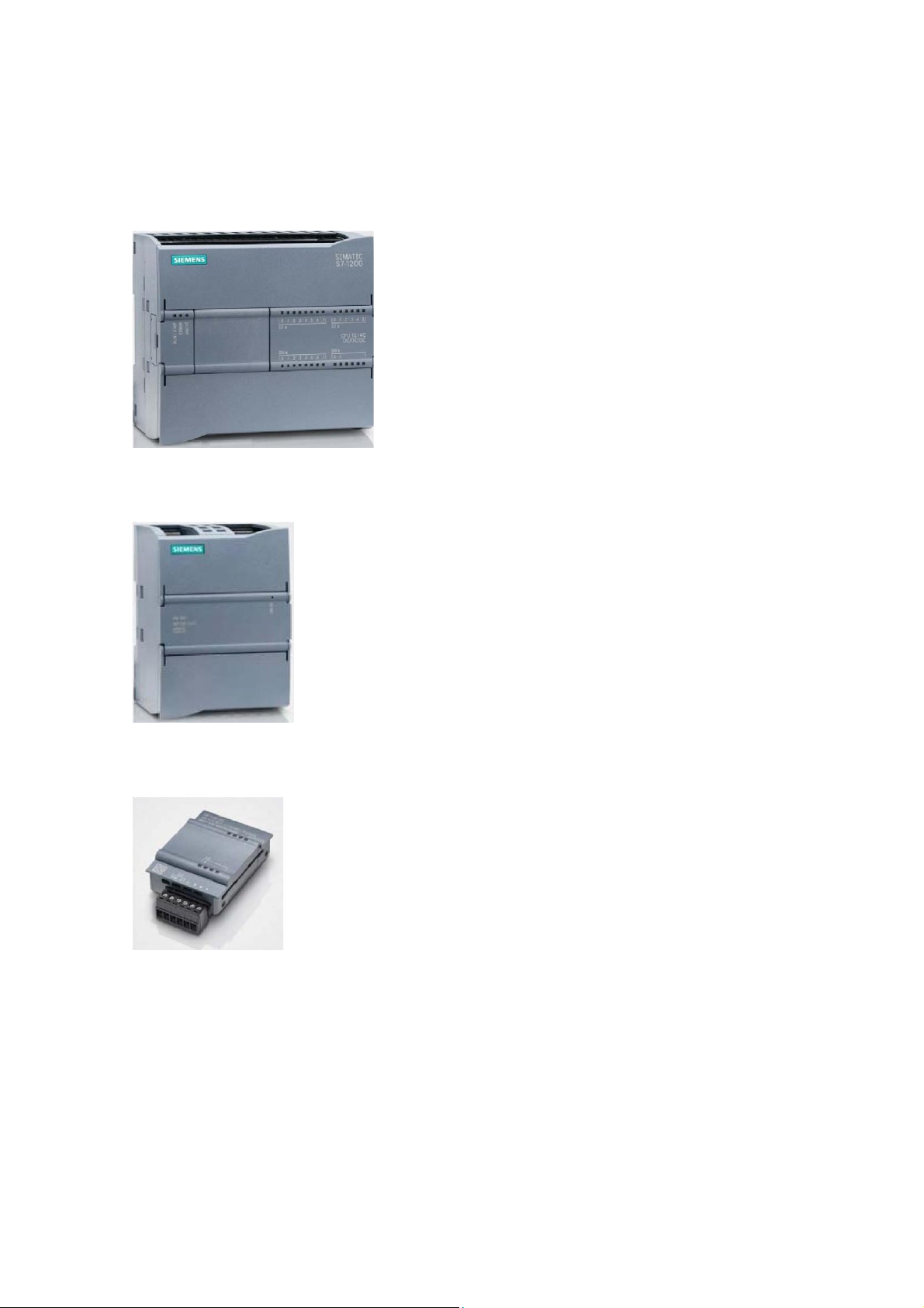
3.2 Operator control and display elements of the CPU 1214C DC/DC/DC
3.2.1 Front view of the CPU 1214C DC/DC/DC
With integrated power supply (24 V connection) and integrated inputs and outputs, the CPU 1214C
DC/DC/DC is immediately ready for use without any other components.
The CPU has an integrated TCP/IP connection for communication with a programming device.
The CPU can thus communicate with HMI devices or other CPUs via an Ethernet network. ① 24 V connection ②
Plug-in terminal block for user wiring (behind the cover flaps) ③
Status LEDs for the integrated I/O and the operating state of the CPU ④
TCP/IP connection (on the underside of the CPU)
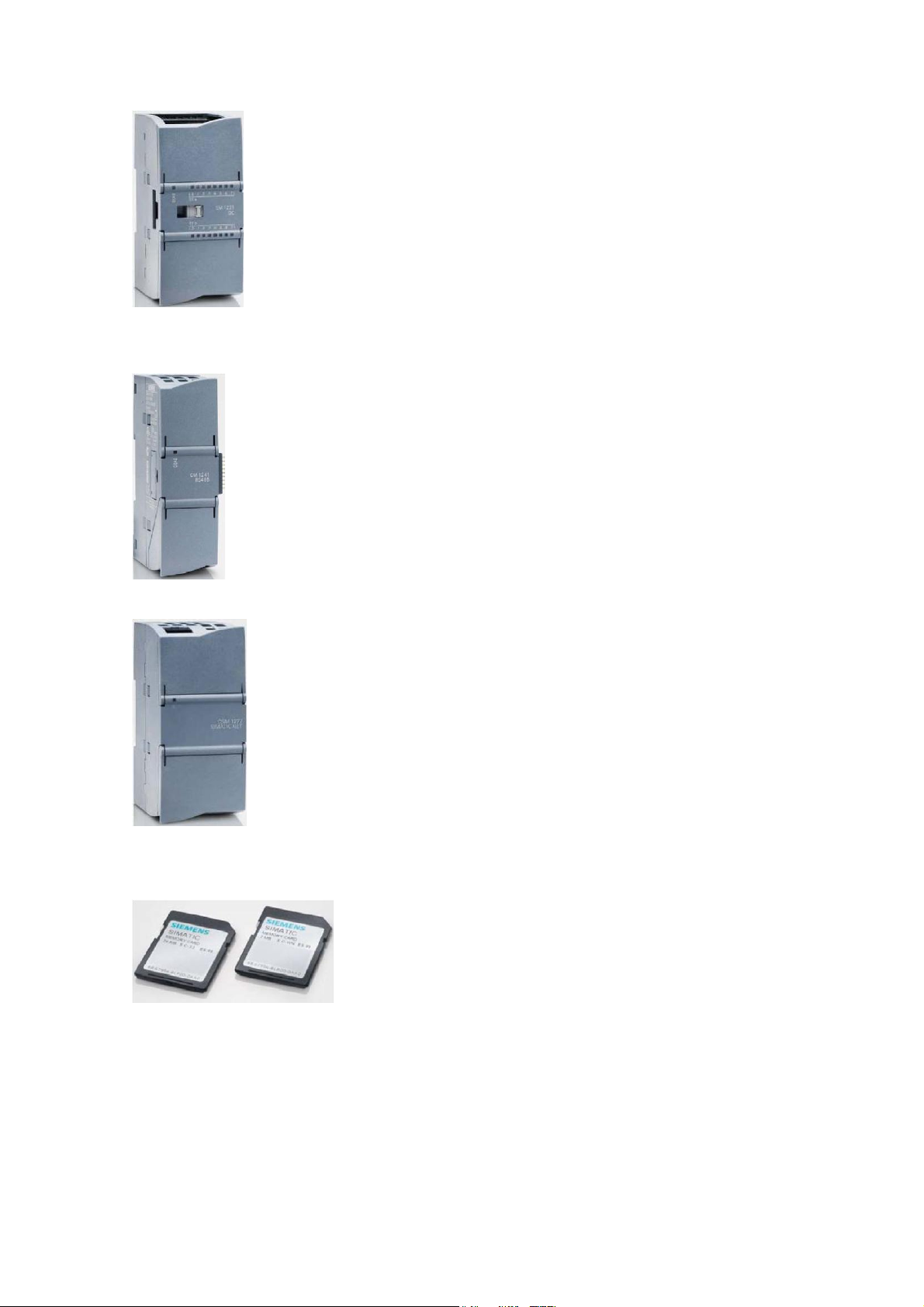
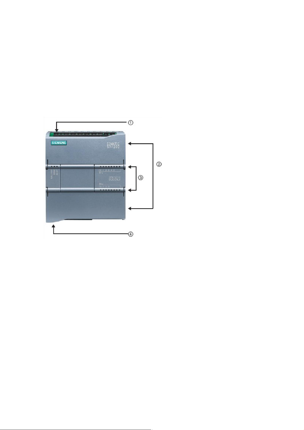
3.2.2 SIMATIC memory card (MC)
The optional SIMATIC memory card (MC) stores a program as well as data, system data, files and projects. It can be used for: -
Transferring a program to multiple CPUs -
Firmware update of CPUs, signal modules (SMs) and communication modules (CMs) - Easy replacement of the CPU lOMoAR cPSD| 58605085
SCE Training Curriculum | TIA Portal Module 011-100, Edition 02/2016 | Digital Factory, DF FA
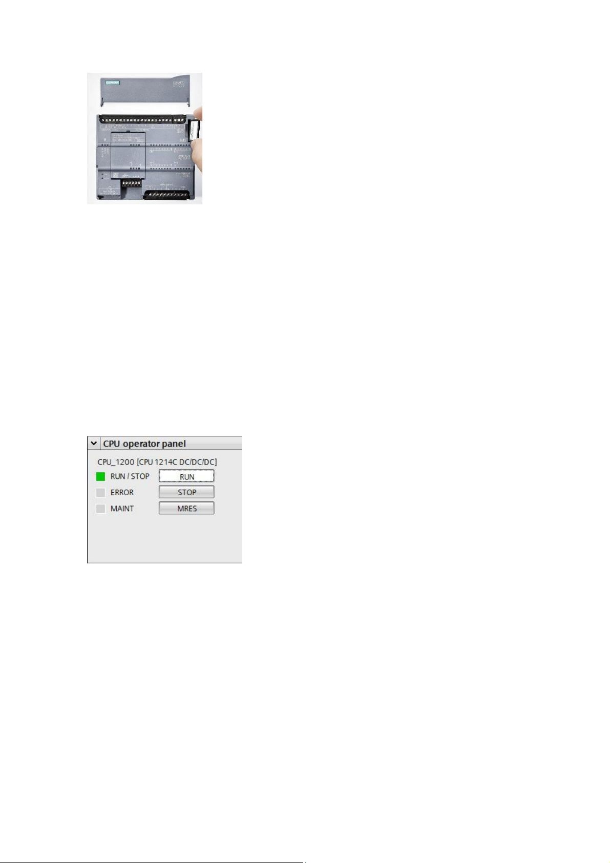
3.2.3 Operating states of the CPU
The CPU can have the following three operating states:
● In the STOP operating state, the CPU is not executing the program and you can download a project.
● In the STARTUP operating state, the CPU is starting up.
● In the RUN operating state, the program is cyclical y executed.
The CPU does not have a physical switch for changing the operating state.
You use the button on the operator panel of the STEP 7 Basic software to change the operating
state (STOP or RUN). The operator panel also contains an MRES button for performing a memory
reset and displays the status LEDs of the CPU.
3.2.4 Status and error displays
The RUN/STOP status LED on the front side of the CPU indicates the current operating state of
the CPU by the color of the display. lOMoAR cPSD| 58605085
SCE Training Curriculum | TIA Portal Module 011-100, Edition 02/2016 | Digital Factory, DF FA ● Yellow light indicates STOP operating state. ● Green light indicates RUN operating state. ● A flashing light
indicates STARTUP operating state.
There are two additional LEDs here: ERROR LED for indicating errors and MAINT LED for
indicating that maintenance is required.
3.3 STEP 7 Basic V13 (TIA Portal V13) programming software
The STEP 7 Basic V13 (TIA Portal V13) software is the programming tool for the
following automation systems: - SIMATIC S7-1200 - Basic Panels
STEP 7 Basic V13 provides the following functions for automation of a system: -
Configuration and parameter assignment of the hardware -
Specification of the communication - Programming -
Testing, commissioning and servicing with operational/diagnostic functions - Documentation -
Creation of visualizations for SIMATIC Basic Panels using the integrated WinCC Basic software
Support is provided for al functions through detailed online help. 3.3.1 Project
To implement a solution for an automation and visualization task, you create a project in the TIA
Portal. A project in the TIA Portal contains the configuration data for the configuration and
internetworking of devices as well as the programs and the configuration of the visualization.
3.3.2 Hardware configuration
The hardware configuration includes the configuration of the devices, consisting of the hardware of
the automation system, the field devices on the PROFINET bus system and the hardware for
visualization. The configuration of the networks specifies the communication between the various
hardware components. Individual hardware components are inserted in the hardware configuration from catalogs. lOMoAR cPSD| 58605085
SCE Training Curriculum | TIA Portal Module 011-100, Edition 02/2016 | Digital Factory, DF FA
The hardware of SIMATIC S7-1200 automation systems comprises the controller (CPU), the signal
modules for input and output signals (SMs), the communication modules (CMs) and other specialpurpose modules.
The signal modules and the field devices connect the input and output data of the process to be
automated and visualized to the automation system.
The hardware configuration enables the downloading of automation and visualization solutions to
the automation system and access to the connected signal modules by the controller.
3.3.3 Planning the hardware
Before you can configure the hardware, you must plan it (hardware planning). In general, you begin
by selecting which control ers are needed and how many. You then select the communication
modules and signal modules. The selection of signal modules is based on the number and type of
inputs and outputs needed. As the final step, a power supply that ensures the necessary power
supply must be selected for each controller or field device.
The functionality required and the ambient conditions are of vital importance for planning the
hardware configuration. For example, the temperature range in the application area sometimes
limits which devices are available for selection. Fail-safe operation might be another requirement.
The TIA Selection Tool (Select automation technology TIA Selection Tool and fol ow the
instructions) provides you support. Note: The TIA Selection Tool requires Java.
Note for online research: If more than one manual is available, you should look for the
description "Device Manual", "Product Manual" or simply "Manual" (as opposed to
"Function Manual", "List Manual", "System Manual", etc.) in order to find the device specifications. lOMoAR cPSD| 58605085
SCE Training Curriculum | TIA Portal Module 011-100, Edition 02/2016 | Digital Factory, DF FA
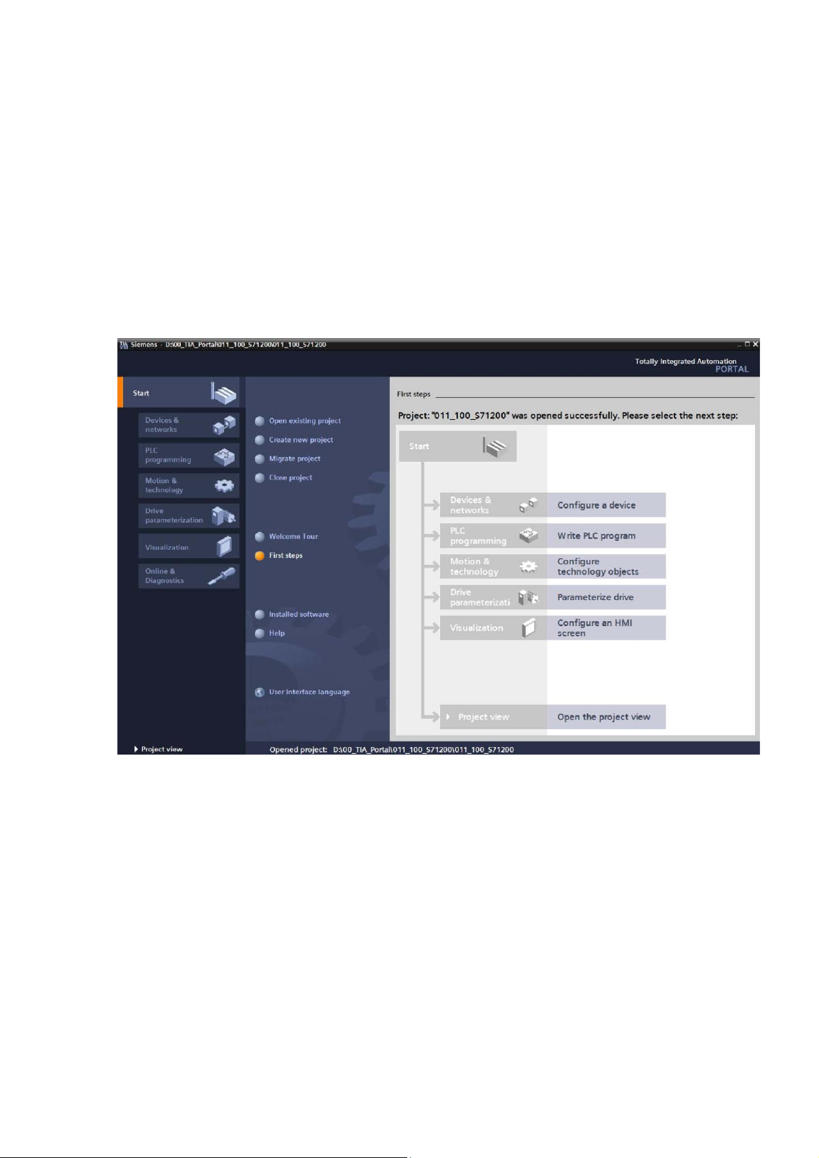
3.3.4 TIA Portal – Project view and portal view
The TIA Portal has two important views. When started, the TIA Portal displays the portal view by
default. This view makes getting started easier, especially for beginning users.
The portal view provides a task-oriented view of the tools for working on the project. Here, you can
quickly decide what you want to do and open the tool for the task at hand. If necessary, a change
to the project view takes place automatical y for the selected task.
Figure 1 shows the portal view. At the bottom left, there is an option to switch between this view and the project view. Figure 1: Portal view
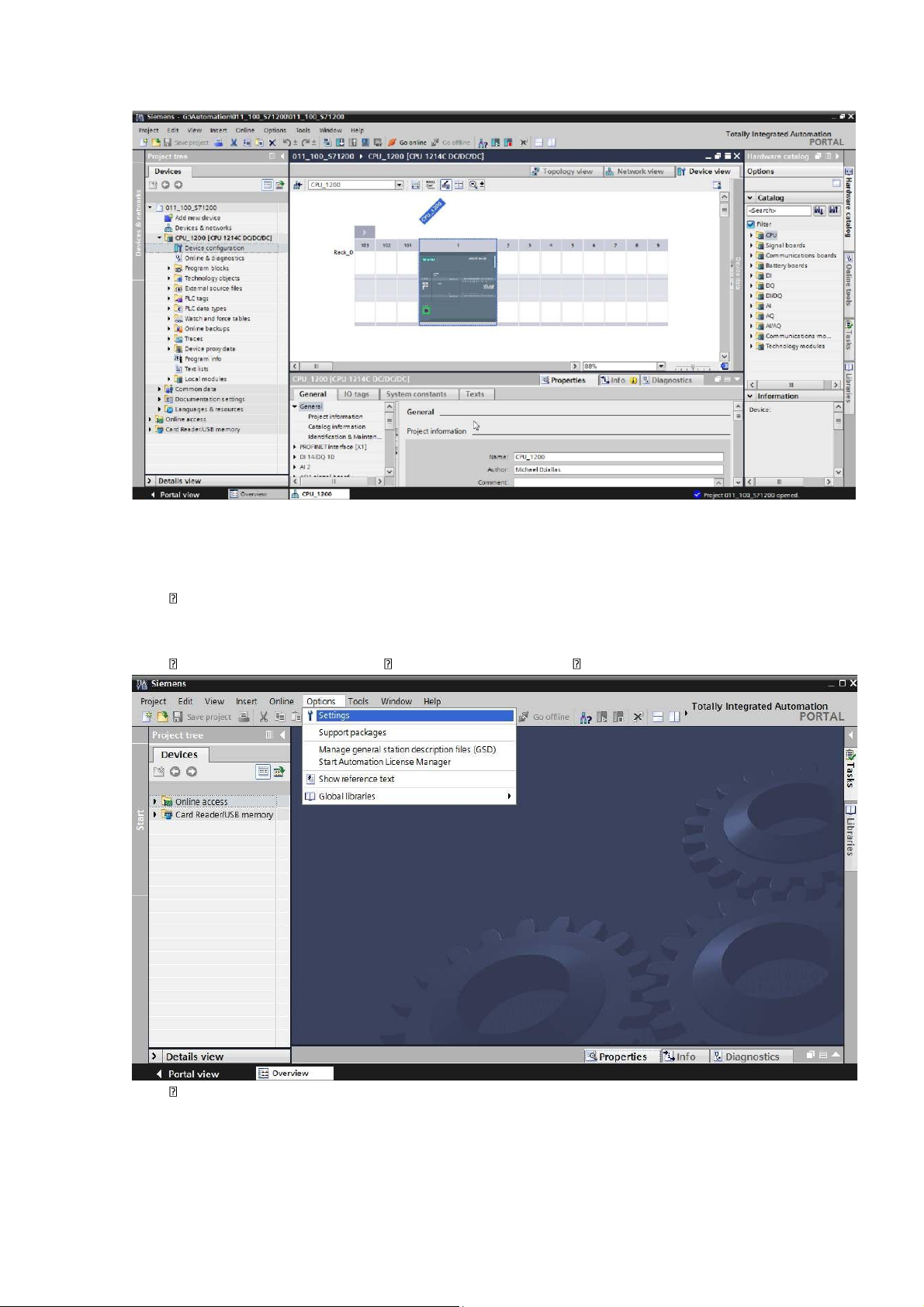
The project view, as shown in Figure 2, is used for hardware configuration, programming, creation
of the visualization and many other tasks.
By default, the project view displays the menu bar with the toolbars at the top, the project tree with
all components of a project on the left and the so-cal ed "task cards" with instructions and libraries, for example, on the right.
If an element (for example, the device configuration) is selected in the project tree, it is displayed in
the center and can be worked on there. lOMoAR cPSD| 58605085
SCE Training Curriculum | TIA Portal Module 011-100, Edition 02/2016 | Digital Factory, DF FA Figure 2: Project view
3.3.5 Basic settings for the TIA Portal
Users can specify their own default settings for certain settings in the TIA Portal. A few
important settings are shown here.
In the project view, select the "Options" menu and then "Settings".
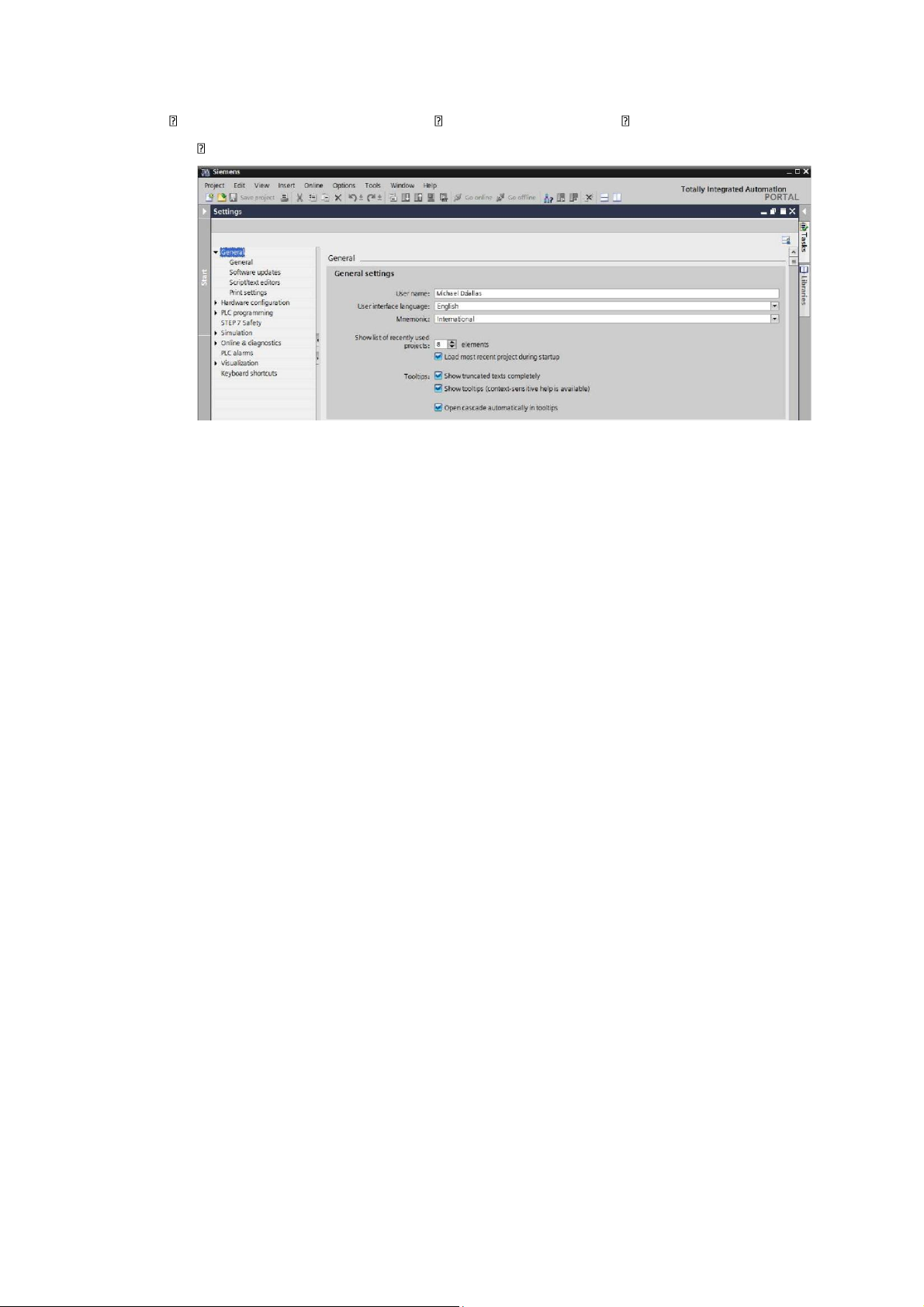
One basic setting is the selection of the user interface language and the language for the
program display. In the curriculums to follow, "English" will be used for both settings. lOMoAR cPSD| 58605085
SCE Training Curriculum | TIA Portal Module 011-100, Edition 02/2016 | Digital Factory, DF FA
Under "General" in "Settings", select "User interface language English" and "Mnemonic International".
Note: These settings can always be changed. lOMoAR cPSD| 58605085
SCE Training Curriculum | TIA Portal Module 011-100, Edition 02/2016 | Digital Factory, DF FA
3.3.6 Set the IP address on the programming device
To program an SIMATIC S7-1200 controller from the PC, the programming device or a laptop,
you need a TCP/IP connection or an optional PROFIBUS connection.
For the PC and SIMATIC S7-1200 to communicate with each other via TCP/IP, it is important that
the IP addresses of both devices match.
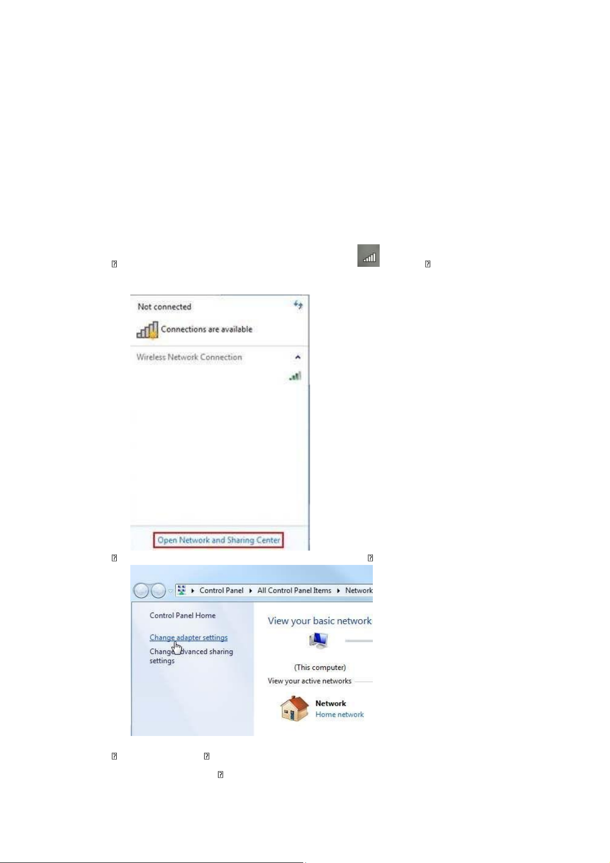
First, we show you how to set the IP address of a PC with Windows 7 operating system.
Locate the network icon in the taskbar at the bottom and click "Open Network and Sharing Center".
In the open Network and Sharing Center window, click "Change adapter settings".
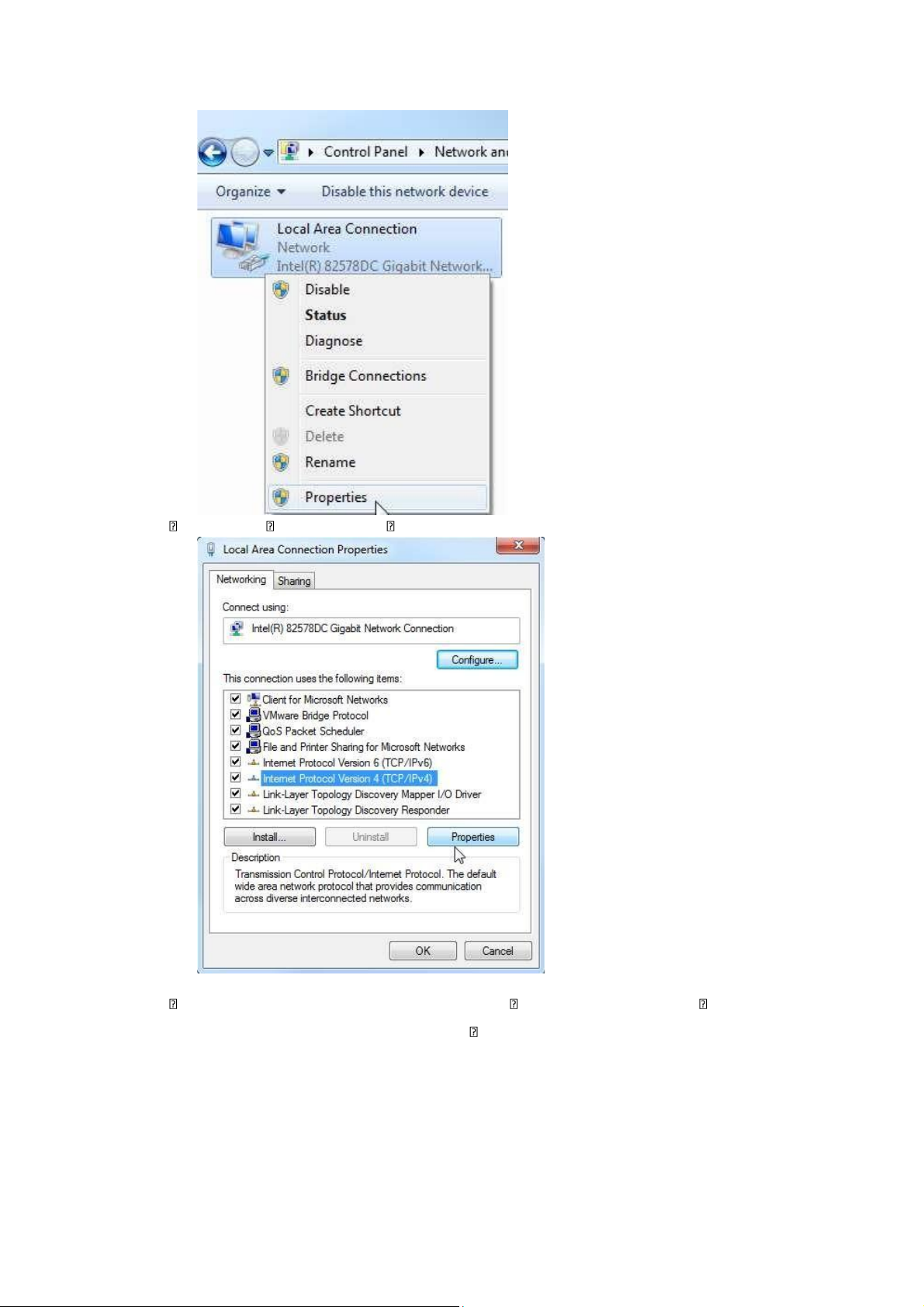
Select the desired "Local Area Connection" that you want to use to connect to the
controller and click "Properties". lOMoAR cPSD| 58605085
SCE Training Curriculum | TIA Portal Module 011-100, Edition 02/2016 | Digital Factory, DF FA
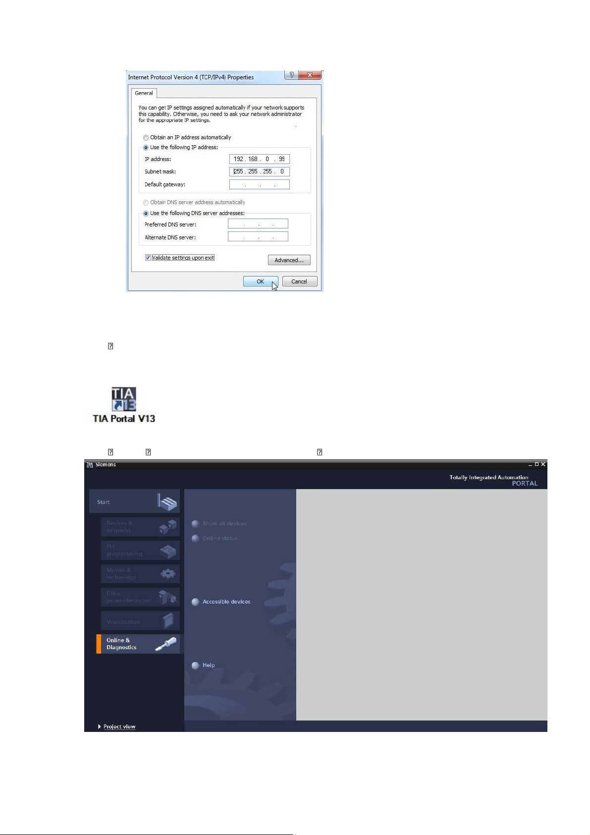
Next, select "Properties" for "Internet Protocol Version 4 (TCP/IP)".
You can use the fol owing address, for example IP address: 192.168.0.99 Subnet mask
255.255.255.0 and accept the settings ( "OK") lOMoAR cPSD| 58605085
SCE Training Curriculum | TIA Portal Module 011-100, Edition 02/2016 | Digital Factory, DF FA
3.3.7 Set the IP address in the CPU
The IP address of SIMATIC S7-1200 is set as follows.
Select the Totally Integrated Automation Portal for this, which is opened here with a double- click (® TIA Portal V13)
Select "Online & diagnostics", and open the "project view". lOMoAR cPSD| 58605085
SCE Training Curriculum | TIA Portal Module 011-100, Edition 02/2016 | Digital Factory, DF FA
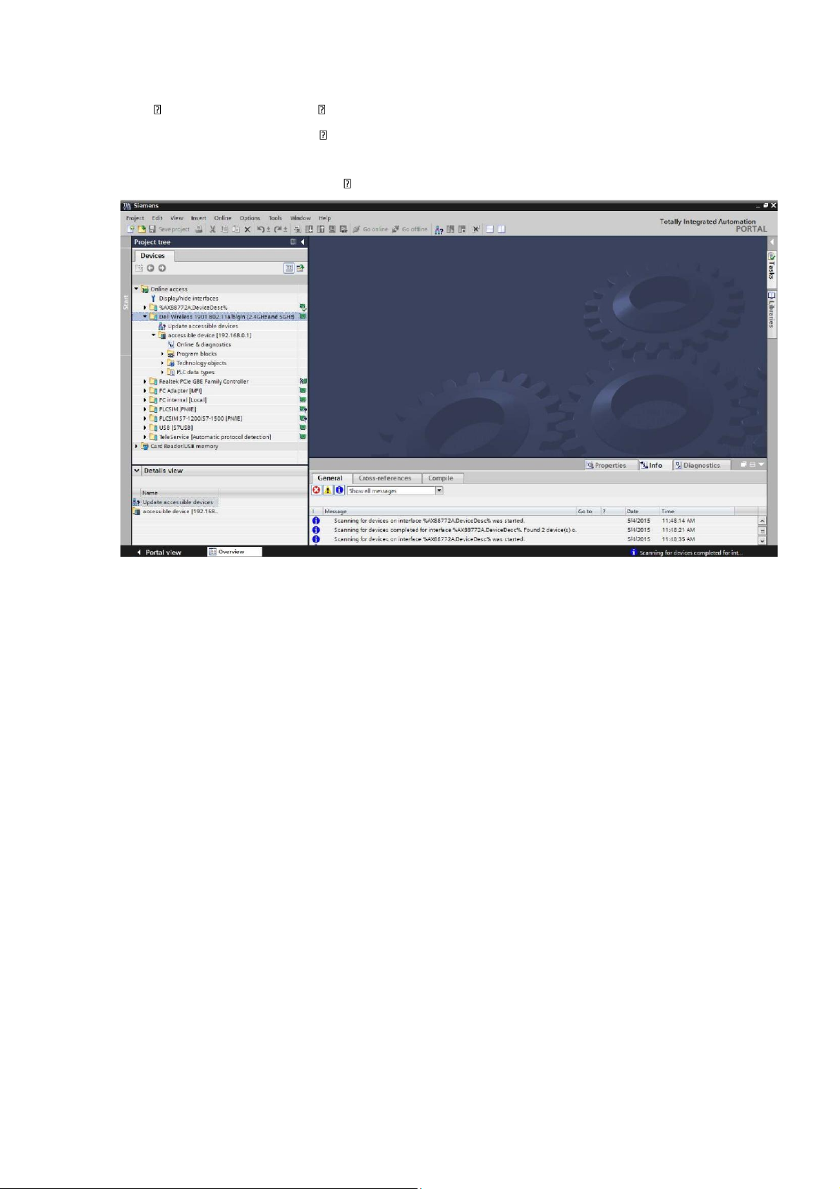
In the project tree under "Online access", select the network adapter that was set
previously. If you click "Update accessible devices" here, you see the IP address (if
previously set) or the MAC address (if IP address not yet assigned) of the connected
SIMATIC S7-1200. Select "Online & diagnostics" here. lOMoAR cPSD| 58605085
SCE Training Curriculum | TIA Portal Module 011-100, Edition 02/2016 | Digital Factory, DF FA
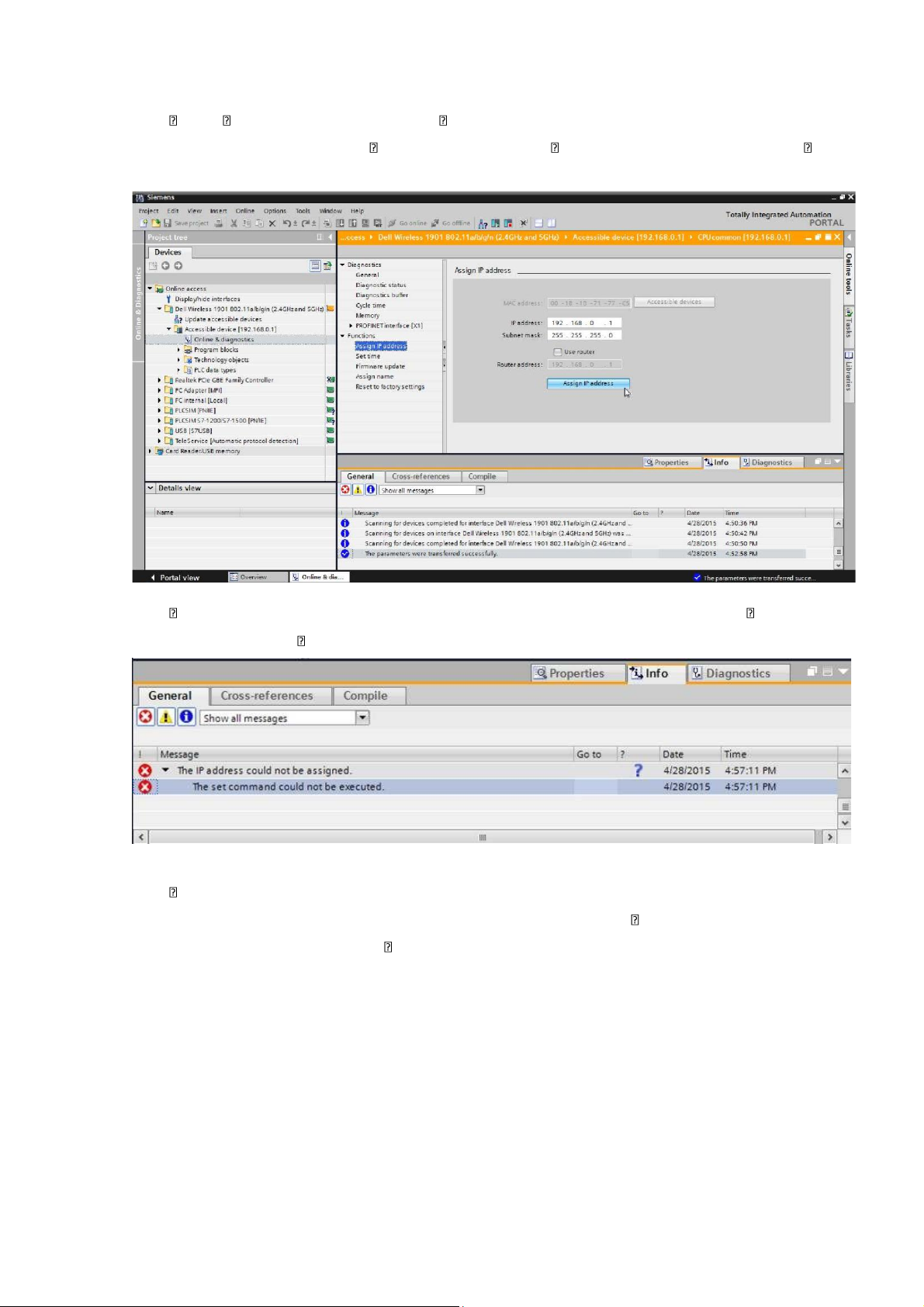
Under "Functions", you now find the "Assign IP address" item. Enter the following IP
address here (example): IP address: 192.168.0.1 Subnet mask 255.255.255.0. Click
"Assign IP address" and this new address wil be assigned to your SIMATIC S7-1200.
If the IP address was not successfully assigned, you will receive a message in the "Info" window under "General".
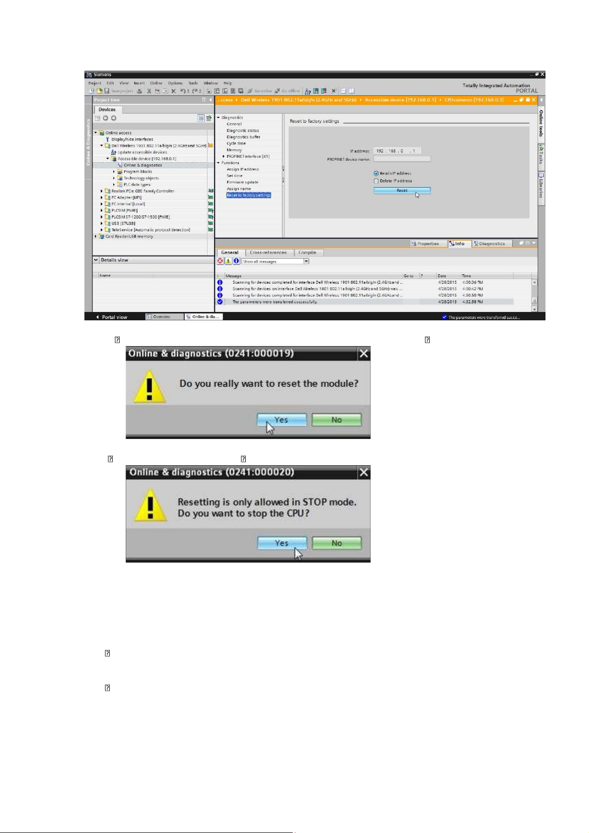
3.3.8 Restore the factory settings of the CPU
If the IP address could not be assigned, the program data on the CPU must be deleted. This
is done by resetting the CPU. To reset the control er, select the "Reset to factory
settings" function and click "Reset". lOMoAR cPSD| 58605085
SCE Training Curriculum | TIA Portal Module 011-100, Edition 02/2016 | Digital Factory, DF FA
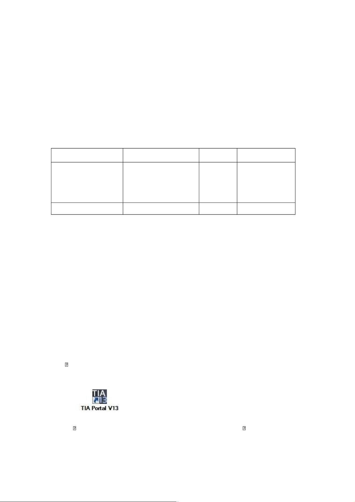
Confirm the prompt asking if you real y want to reset the module with "Yes".
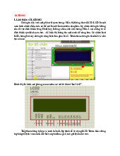
If necessary, stop the CPU. ( "Yes") 4 Task
Create a project and add the modules of the existing hardware (here: Trainer Package SIMATIC
S7-1200 with CPU 1214C) by using the automatic hardware detection of the TIA Portal. The
following modules must be detected:
SIMATIC S7-1200, CPU 1214C DC/DC/DC
(Order number: 6ES7 214-1AG40-0XB0)
1X SIMATIC S7-1200, signal board ANALOG OUTPUT SB1232, 1 AO (Order number: 6ES7 232-4HA30-0XB0) lOMoAR cPSD| 58605085
SCE Training Curriculum | TIA Portal Module 011-100, Edition 02/2016 | Digital Factory, DF FA 5 Planning
Because this is a new system, a new project must be created.
The hardware for this project is already specified by the existing hardware (here: SIMATIC S7-1200
Trainer Package). Therefore, a selection does not have to be made. Instead, the listed modules of
the Trainer Package are detected directly. The order numbers (see Task or Table 1) can be used for checking purposes.
The Ethernet interface must be set for the configuration of the CPU. For the digital and analog
inputs and outputs, the address areas corresponding to Table 1 will be set. Module Order number Slot Address area CPU 1214C DC/DC/DC 6 ES7 214-1AG40-0XB 0 1 DI 0.0 -1.5 DQ 0.0 - 1.1 AI 64 / 66 SB1232, 1 AO 6 ES7 232-4HA30-0XB 0 AO 64
Table 1: Overview of the planned configuration
As the final step, the hardware configuration must be compiled and downloaded. Any errors
present can be detected during compiling and incorrect modules can be detected when the
controller is started (only possible when hardware is present and instal ed identically).
The tested project must be saved and archived.
6 Structured step-by-step instructions
You can find instructions on how to carry out planning below. If you already have the relevant
previous knowledge, it wil be sufficient to focus on the numbered steps. Otherwise, simply fol ow
the steps in the instructions.
6.1 Create a new project
Select the Totally Integrated Automation Portal for this, which is opened here with a double- click (® TIA Portal V13)
In the portal view under the "Start" menu, select the command "Create new project".
Tài liệu liên quan:
-
Hướng dẫn sử dụng & lập trình màn hình 16x2 | Môn Applied Machine Learning - Đại học Sư phạm Kỹ thuật Thành phố Hồ Chí Minh
144 72 -
Yolov5 - detecting and recognizing hand sign language | Môn Applied Machine Learning - Đại học Sư phạm Kỹ thuật Thành phố Hồ Chí Minh
141 71 -

Điều khiển tự động hóa hệ thống điện công nghiệp | Môn Applied Machine Learning - Đại học Sư phạm Kỹ thuật Thành phố Hồ Chí Minh
97 49 -
Perceptron Training and Logic Function Analysis | Môn Applied Machine Learning - Đại học Sư phạm Kỹ thuật Thành phố Hồ Chí Minh
131 66