Chapter 10 Advanced Welding Symbols
Chapter 10 Advanced Welding Symbols
Môn: Tài liệu Tổng hợp 3.6 K tài liệu
Trường: Tài liệu khác 3.9 K tài liệu
Tác giả:

Preview text:
Chapter 10 advanced Welding Symbols Learning ObjecTive
• Be able to interpret AWS welding symbols that include all of the information that could be used on them Key Terms Weld all around Pitch Spacer Field weld Chain intermittent weld Convex contour Weld length Staggered intermittent weld Concave contour Intermittent weld Consumable insert Flush contour Skip weld Backing Melt-through Overview
Many additional elements can be added to the basic parts of the AWS welding
symbol. The additional elements and their placement, along with the basic parts
of the welding symbol, are shown in Figures 10-1 and 10-2. They are described
throughout the remainder of this chapter. weLd aLL arOund
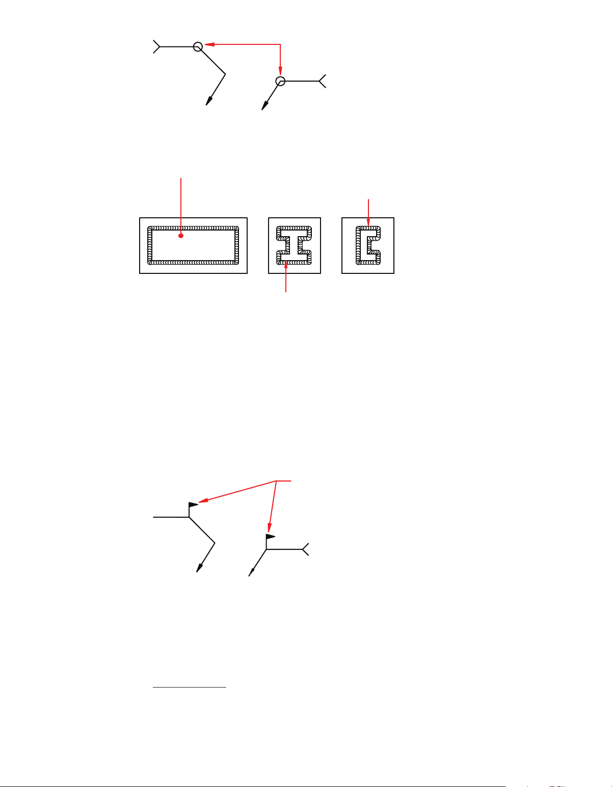
The specification to weld all around requires that the weld be made to
encapsulate the entire joint. In the case of a circular joint, the weld all around
symbol is not required. The weld all around symbol consists of a circle that
is placed over the intersection where the end of the reference line meets the
arrow. Examples of weld all around welds and welding symbols are shown in Figures 10-3 and 10-4. 149
M10_CORG3839_02_SE_C10.indd 149 26/09/15 4:49 pm
Figure 10-1 AWS Standard Locations of the Elements of a Welding Symbol (AWS A2.4:2012,
Figure 3 reproduced and adapted with permission from the American Welding Society (AWS), Miami, FL.)
Figure 10-2 AWS Supplementary Symbols (AWS A2.4:2012, Figure 2 reproduced and adapted with permis-
sion from the American Welding Society (AWS), Miami, FL.) 150 Chapter 10
M10_CORG3839_02_SE_C10.indd 150 26/09/15 4:49 pm Weld All Around Symbols
Figure 10-3 Weld All Around Symbols
PLATE WELDED ON TOP OF ANOTHER PLATE CHANNEL WELDED TO A PLATE BEAM WELDED TO A PLATE
Figure 10-4 Example of Weld All Around Welds FieLd weLd
A field weld is defined by the American Welding Society (AWS) as “[a] weld
made at a location other than a shop or the place of initial construction.”1 The
field weld symbol consists of a flag that is placed at the intersection where the
end of the reference line meets the arrow (see Figure 10-5). Field Weld Symbols
Figure 10-5 Field Weld Symbol Examples
1 AWS A3.0M/A3.0:2010, reproduced with permission from the American Welding Society (AWS), Miami, FL
advanced Welding Symbols 151
M10_CORG3839_02_SE_C10.indd 151 26/09/15 4:49 pm weLd LengTh
Each weld, with the exception of spot and plug welds, has a length component.
The weld length may be the entire length of the joint or some portion thereof.
There are several different methods for providing the weld length information
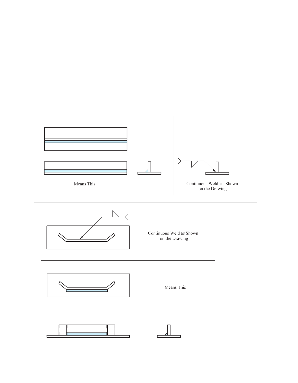
on a drawing. When the weld is to be the entire length of the joint, the length
component is not required on the welding symbol. The welding symbol points
to the joint requiring the weld, and the weld is made the entire length of that par-
ticular joint, as shown in Figure 10-6. If a weld is required to make a change in di-
rection, an additional welding symbol or a multi-arrow symbol should be used.
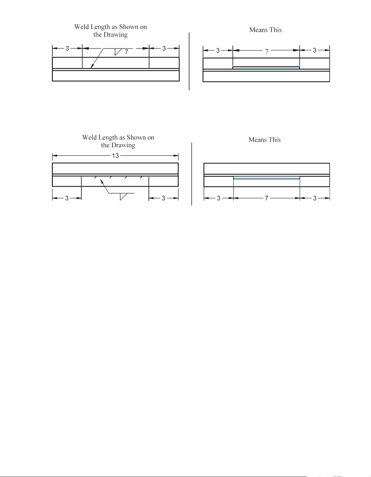
When the weld length is not required to extend the complete length of the
joint, it can be defined by placing the required length to the right of the weld
symbol. The welding symbol then points to the area of the joint requiring the
weld. It may replace the standard length dimension, as shown in Figure 10-7.
Figure 10-6 Examples of Continuous Welds 152 Chapter 10
M10_CORG3839_02_SE_C10.indd 152 26/09/15 4:49 pm
Figure 10-7 Weld Length Specified on Welding Symbol Between Extension Lines
Figure 10-8 Weld Length Specified on Welding Symbol Between Extension Lines with
Section Lines Representing the Weld Area
Placing section lines in the area where the weld is to be placed can also be
used in combination with standard dimensions and welding symbols to iden-
tify the required weld length and weld location. See Figure 10-8. inTermiTTenT weLds
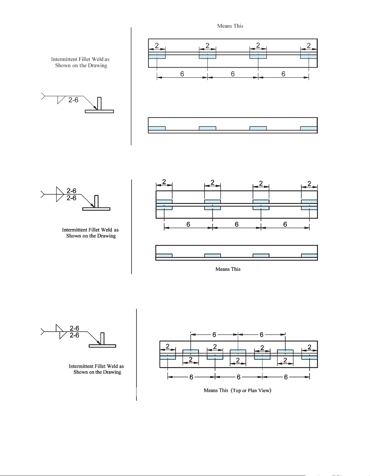
An intermittent weld, also called a skip weld, consists of a series of welds
placed on a joint, with unwelded spaces between each of the welds. The indi-
vidual weld segments in an intermittent weld have a length and pitch compo-
nent. The weld length is the linear distance of each weld segment. The length is
shown in the welding symbol to the right of the weld symbol. The pitch is the
center-to-center distance of each of the weld segments. It is shown to the right
of the length on the welding symbol, with a dash between the two. This concept is shown in Figure 10-9.
When intermittent welds are placed on both sides of a joint, they can be
either directly opposite each other, known as a chain intermittent weld, or they
can be offset, known as a staggered intermittent weld. The chain intermittent
weld is shown in Figure 10-10. The staggered intermittent weld is shown in Figure 10-11.
advanced Welding Symbols 153
M10_CORG3839_02_SE_C10.indd 153 26/09/15 4:49 pm
Figure 10-9 Intermittent Weld
Figure 10-10 Chain Intermittent Weld
Figure 10-11 Staggered Intermittent Weld 154 Chapter 10
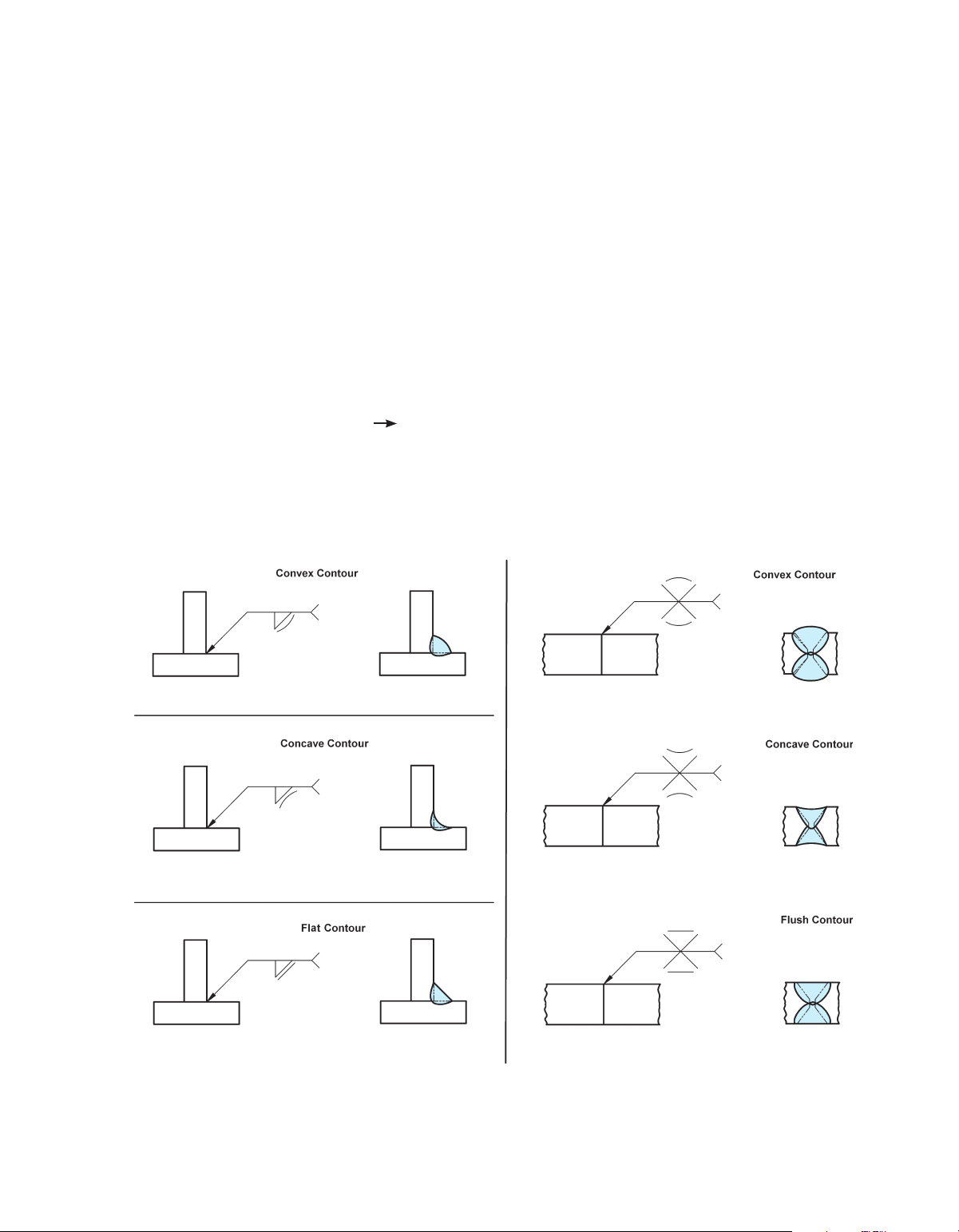
M10_CORG3839_02_SE_C10.indd 154 26/09/15 4:49 pm weLd cOnTOur symbOLs
The contour of a weld refers to the shape of its face. A weld with a convex
contour has a face that protrudes out in a convex shape from its toes; a weld
with a concave contour has a face that is concave (sinks in from its toes); and
a weld with a flush contour has a face that is flush with the base metal, or is
flat from one toe to the other. When required, the contour symbol is added to a
welding symbol so that it is oriented to mimic the required contour of the weld
(see Figure 10-12). When a contour symbol is not added to the welding symbol,
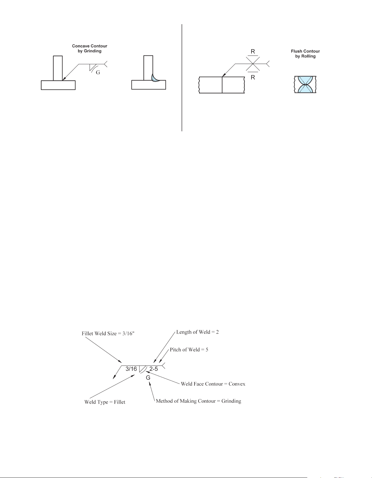
standard welding and shop practices should be followed. Finish symbOLs
Placing a finish symbol adjacent to the contour symbol specifies the method of
making the contour. The finish symbols are made up of letters. The letters and
their corresponding methods are listed below. U = unspecified
This means that any appropriate method may be used. G = grinding M = machining C = chipping
Figure 10-12 Contour Symbols
advanced Welding Symbols 155
M10_CORG3839_02_SE_C10.indd 155 26/09/15 4:49 pm
Figure 10-13 Examples of Contour Symbols with Method of Finish R =rolling H =hammering P =planishing
See Figure 10-13 for an example of a finish Symbol. FiLLeT weLds
A welding symbol for a fillet weld includes the required fillet weld symbol and
(as needed) the size, length, pitch, contour, method of making the contour, weld
all around, field weld, and any other supplemental information listed in the tail
of the welding symbol. See Figure 10-14.
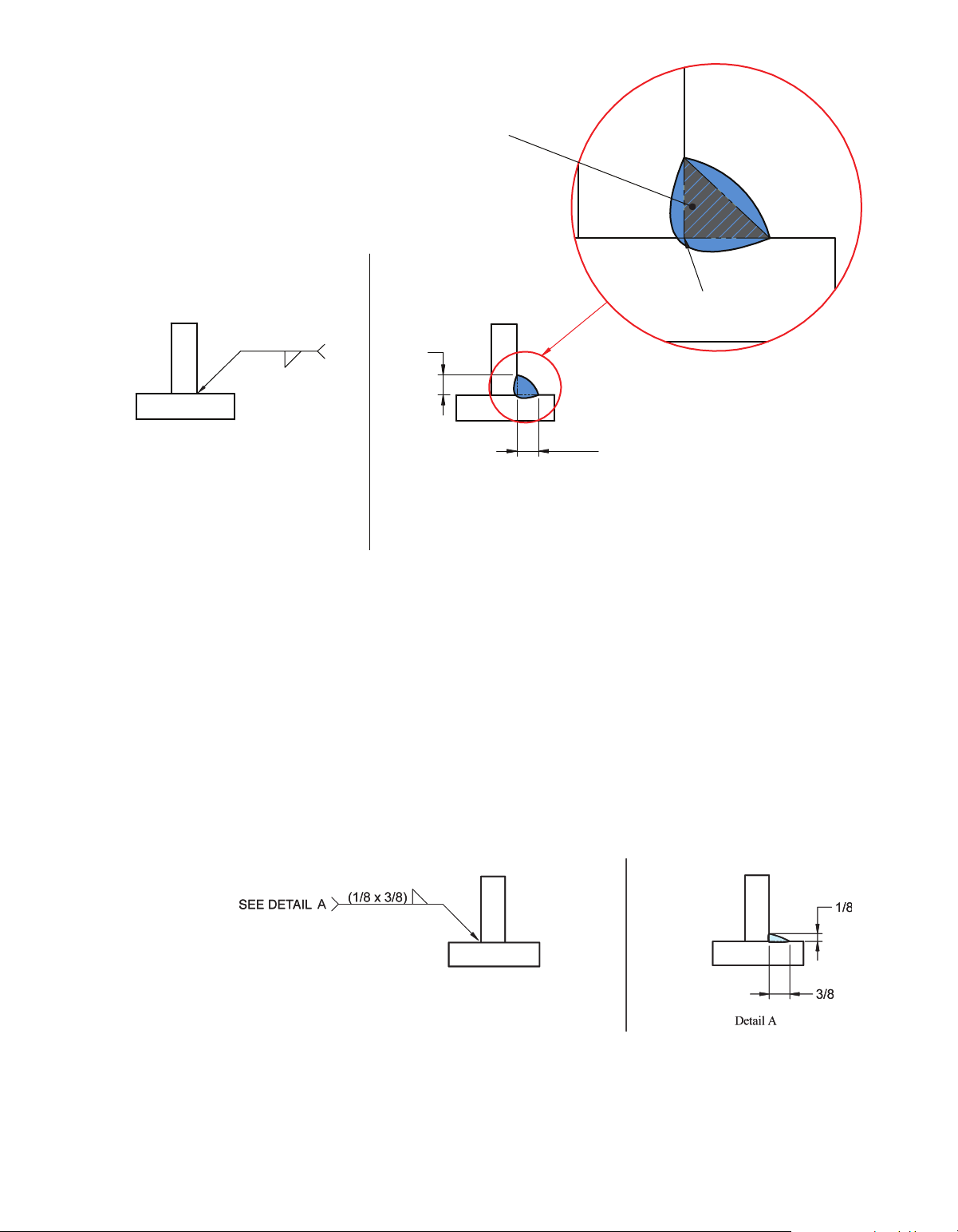
The size of the fillet weld is shown to the left of the weld symbol. It rep-
resents the length of the legs of the largest right triangle that can fit within the
weld at it's smallest point, with the vertex of the triangle located at the intersec-
tion of the two members being joined. See Figure 10-15.
Figure 10-14 Example of a Welding Symbol for a Fillet Weld 156 Chapter 10
M10_CORG3839_02_SE_C10.indd 156 26/09/15 4:49 pm Largest Right Triangle That Can Be Formed Within the Weld
Note: When a fillet weld is measured,
the measurement is taken at the location where it is the smallest. Vertex 3/16 3/16 3/16 This Shown on Means This the Drawing
Figure 10-15 Fillet Weld Size
unequaL Leg FiLLeT weLds
A fillet weld can be required to have unequal legs. In such cases, the size for
each of the legs is shown on the welding symbol to the left of the weld sym-
bol and is written in parentheses. The only way to know which leg goes with
which size is through either a detail drawing that shows the weld joint, as in
Figure 10-16; a note; or other revealing information, such as one of the legs is
required to be longer than one of the sides, as in Figure 10-17.
Figure 10-16 Unequal Leg Fillet with Detail Drawing
advanced Welding Symbols 157
M10_CORG3839_02_SE_C10.indd 157 26/09/15 4:49 pm
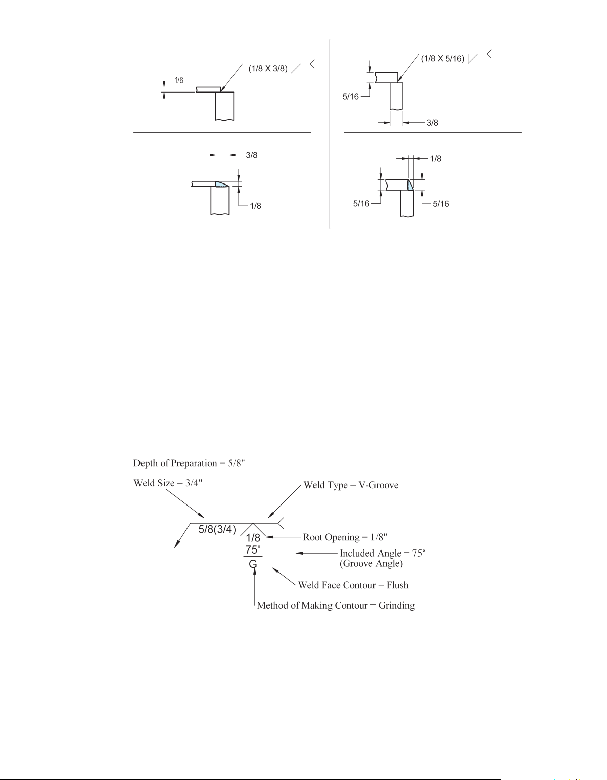
Figure 10-17 Unequal Leg Fillets That Could Be Shown Without Detail grOOve weLds
The welding symbol for a groove weld may include, as needed, the groove
weld symbol, size, depth of preparation, root opening, groove angle (also called
included angle) contour, method of making the contour, length, pitch, weld all
around, field weld, and any other supplemental information listed in the tail of
the welding symbol. See Figures 10-18 and 10-19. When the type of joint prepa-
ration (joint geometry) is optional, the weld symbol may be omitted. In such
cases, an empty reference line with the letters CJP in the tail indicate a complete
joint penetration weld. In other cases of optional joint geometry, the weld size
shown in parenthesis, may be the only item on the reference line.
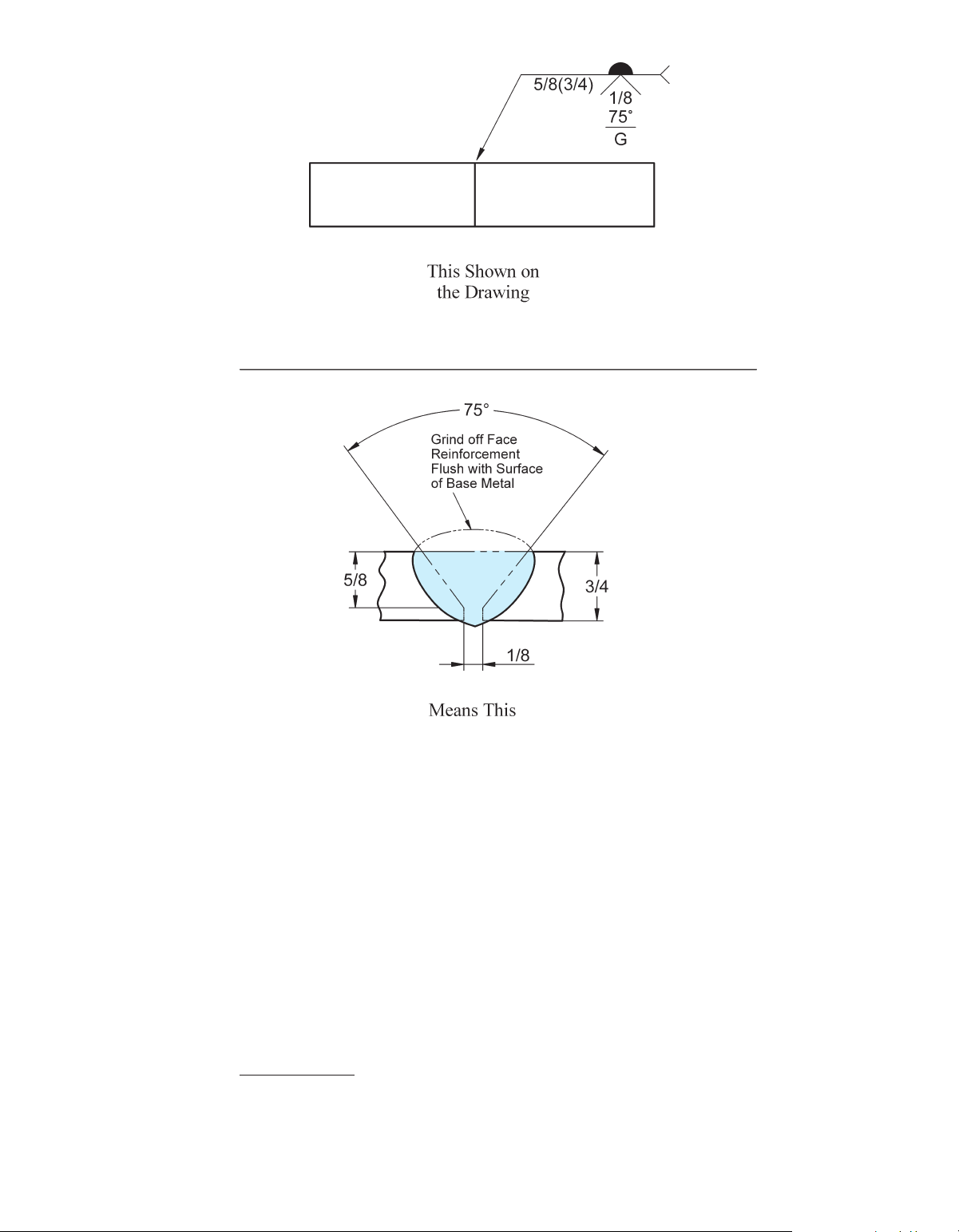
Figure 10-18 Welding Symbol Example for a Groove Weld 158 Chapter 10
M10_CORG3839_02_SE_C10.indd 158 26/09/15 4:49 pm
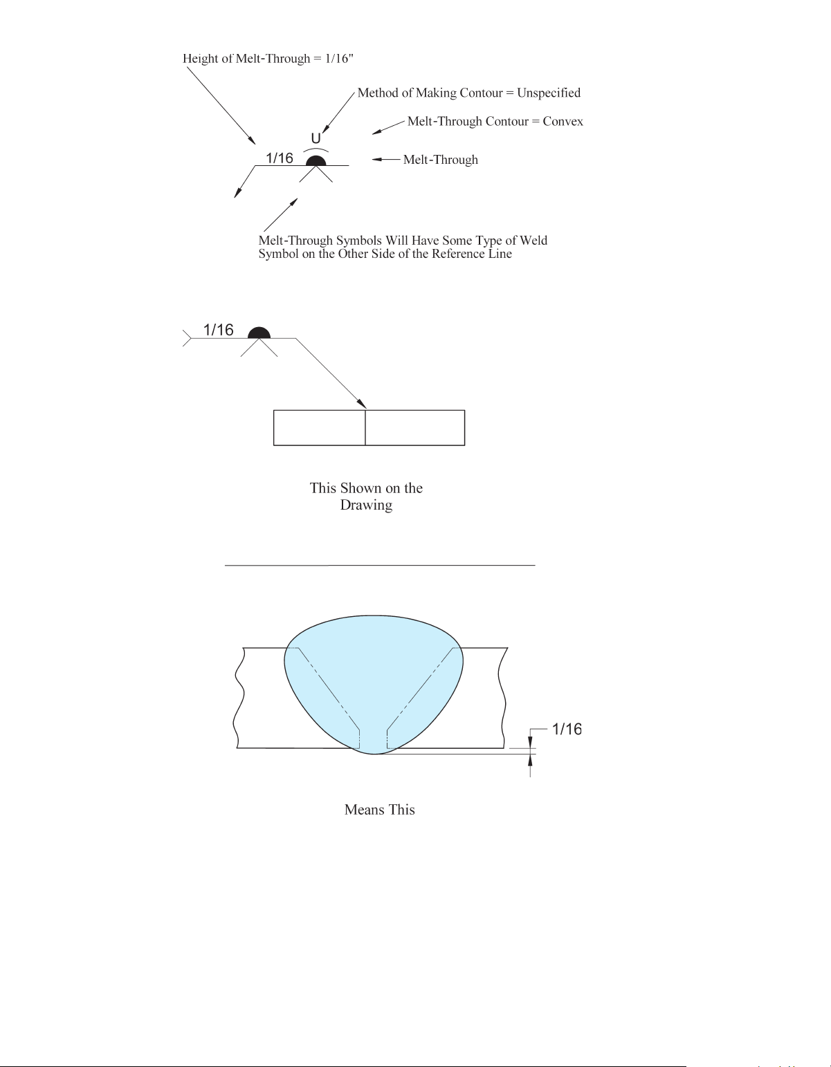
Figure 10-19 Example of a Groove Weld meLT-ThrOugh
Melt-through is defined by the American Welding Society (AWS) as “visible
root reinforcement produced in a joint welded from one side.”2 In other words,
melt-through is the penetrated weld metal that extends beyond the base metal on
the backside of a joint welded from the opposite side. Height, contour, method
of contour, and tail specifications are all supplemental types of information that
can be added to the melt-through weld symbol. See Figures 10-20 and 10-21.
2 AWS A3.0M/A3.0:2010, reproduced with permission from the American Welding Society (AWS), Miami, FL
advanced Welding Symbols 159
M10_CORG3839_02_SE_C10.indd 159 26/09/15 4:49 pm
Figure 10-20 Welding Symbol with Melt-Through
Figure 10-21 Melt-Through Example 160 Chapter 10
M10_CORG3839_02_SE_C10.indd 160 26/09/15 4:49 pm cOnsumabLe inserT
A consumable insert is preplaced filler metal that is fused into the root of the
joint. Consumable inserts come in five different classes. The five classes corre-
late to the following five shapes:
1. Class 1: Inverted T cross section
2. Class 2: J shaped cross section
3. Class 3: Solid ring shape
4. Class 4: Y shaped cross section
5. Class 5: Rectangular shaped cross section
The class number (1, 2, 3, 4, or 5) required for the application should
be shown in the tail of the welding symbol (see Figure 10-22). AWS A5.30/
A5.30M:2007 Specification for Consumable Inserts further defines and specifies
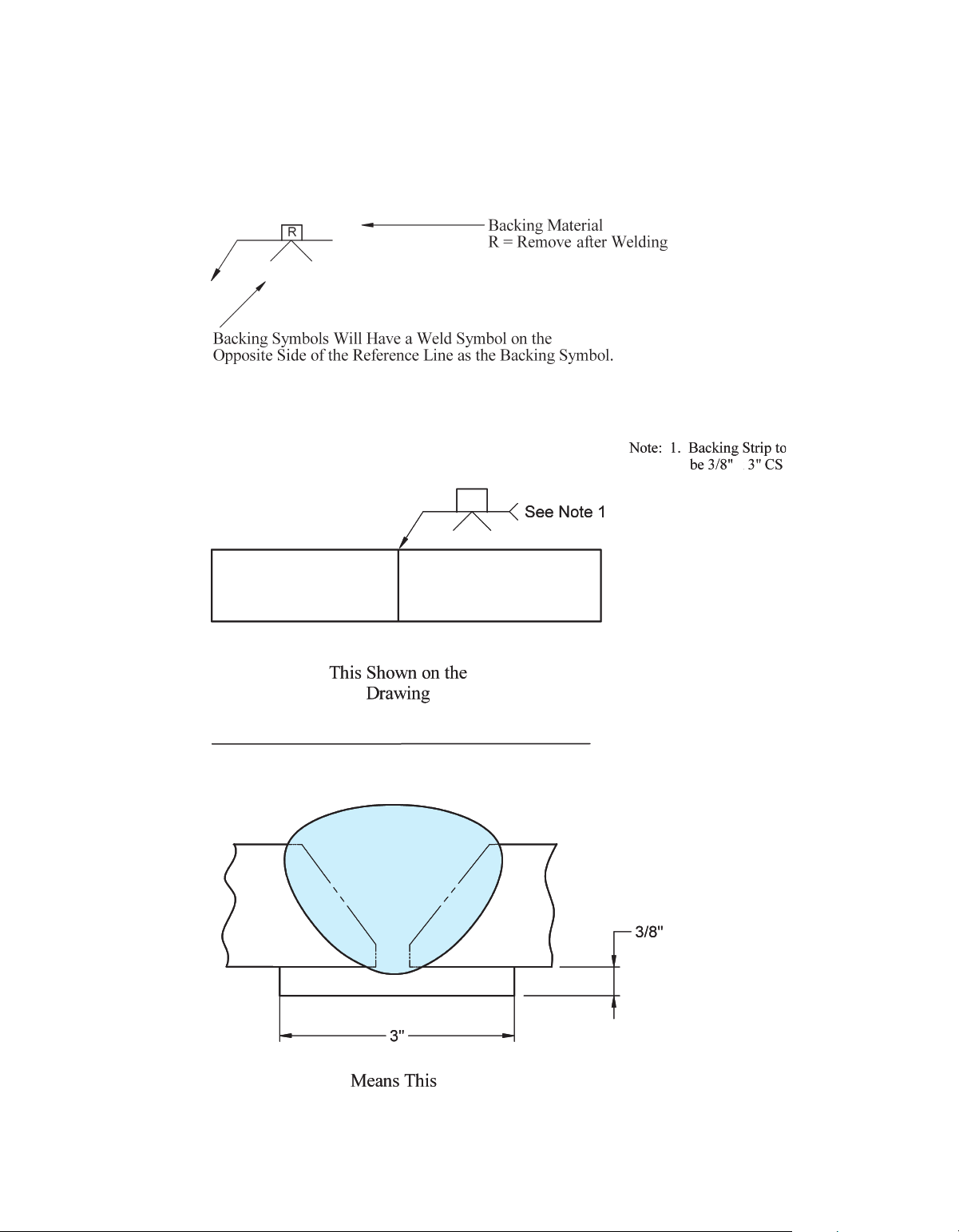
the requirements of the five classes of consumable inserts. bacKing
Backing refers to placing something against a weld joint to support the molten
metal. In most cases, it is placed against the backside of the weld joint, thus
the term backing. For certain instances, however, like electroslag and electrogas
welding, it can be used on both sides of the weld joint because both sides of the
joint have molten metal at the same time and both sides must be supported.
There are many types of backing, including backing bar or backup bar, backing
pass, backing weld, backing ring, backing shoe, and backing strip. There are
many methods for applying backing. Backing can be made from material that CLASS 1 INSERT This Shown on the Drawing Means CONSUMABLE INSERT This
Figure 10-22 Melt-Through Example
advanced Welding Symbols 161
M10_CORG3839_02_SE_C10.indd 161 26/09/15 4:49 pm
will fuse into the weld or it can be made from material that will not fuse into
the weld. Fused backing can be required to be removed after welding or left
on to become part of the completed weld joint. When backing is to be removed
after welding, an “R” is placed within the perimeter of the backing symbol.
Figure 10-23 shows a backing symbol with an “R,” indicating backing material
that is to be removed after welding. Figure 10-24 shows a welding symbol and
Figure 10-23 Welding Symbol with Backing Material *
Figure 10-24 Backing Strip Weld 162 Chapter 10
M10_CORG3839_02_SE_C10.indd 162 26/09/15 4:49 pm
weld for a joint that is to have a backing strip that is to be left on after welding.
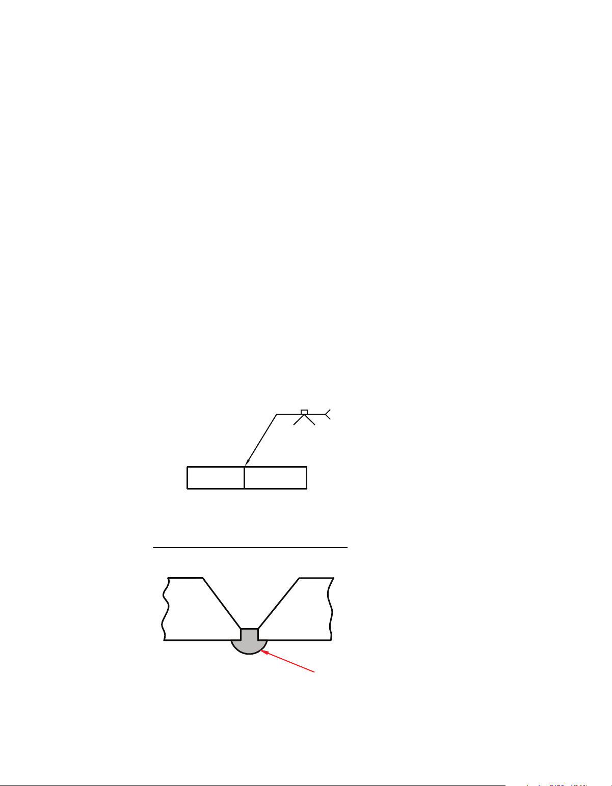
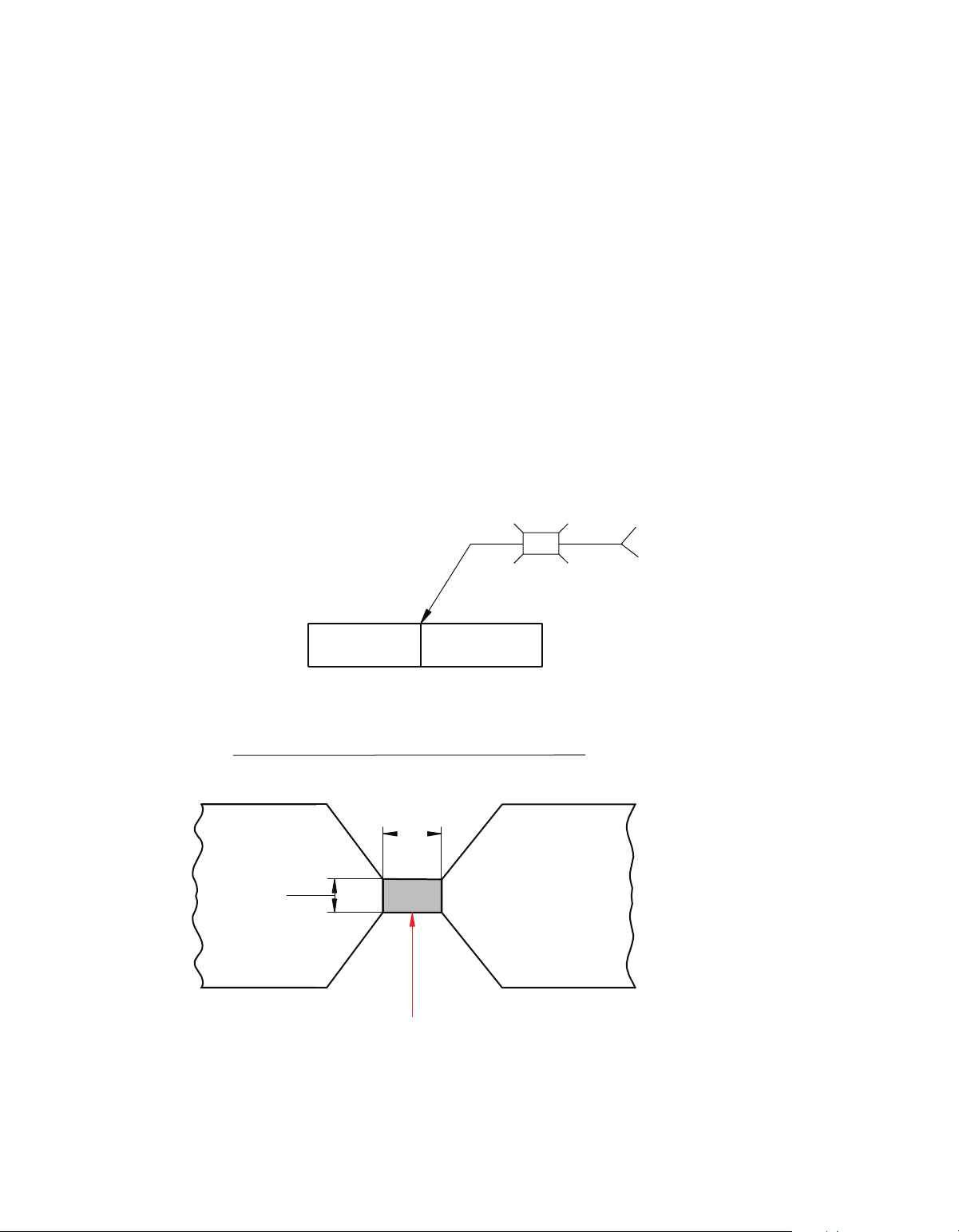
Notice there is no “R,” used in this symbol. spacer
For certain applications, a spacer can be used between weld joint members. The
requirement to use a spacer is shown by the spacer symbol, which is a rectan-
gular box placed on the center of the reference line, as shown in Figure 10-25.
When the spacer symbol is used, the size and type of material should be shown
in the tail of the welding symbol.
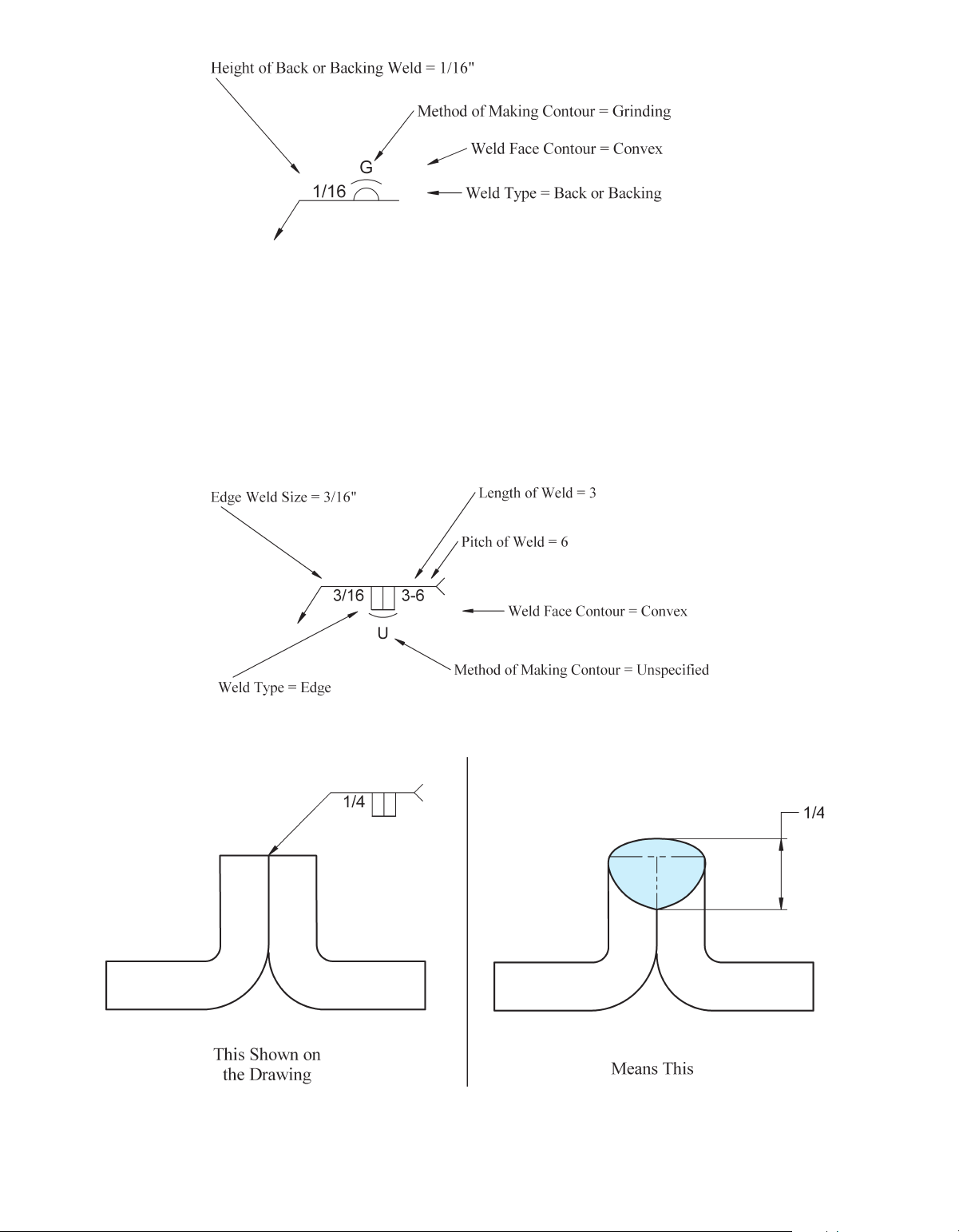
bacKing weLds and bacK weLds
Backing welds and back welds use the same weld symbol, which looks like an
unshaded half circle. Determination of which type (backing weld vs. back weld)
is required based on the symbol alone cannot be made. A note in the tail of the
welding symbol may be provided to specify which type of weld is required, a
multiple reference line may be used to indicate the sequence of operation, or
it may be specified in the welding procedure. Height, contour, and method of
contour are all types of information that can be added to the back or backing weld symbol. See Figure 10-26. 5/16 * 1/2 - 1018 This Shown on the Drawing 1 /2 5 /16 SPACER Means This Figure 10-25 Spacer
advanced Welding Symbols 163
M10_CORG3839_02_SE_C10.indd 163 26/09/15 4:49 pm
Figure 10-26 Backing Welds and Back Welds edge weLds
The welding symbol for an edge weld includes the edge weld symbol and when
required, the following additional information: size, length, pitch, contour and
method of finish. When the size of an edge weld is specified, it refers to the throat
of the weld (the distance from the root to the face of the weld). Figure 10-27
shows the symbol for an edge weld with all of the supplemental information that
may be used. Figure 10-28 shows the meaning of the weld size for an edge weld.
Figure 10-27 Edge Welding Symbol Figure 10-28 Edge Weld 164 Chapter 10
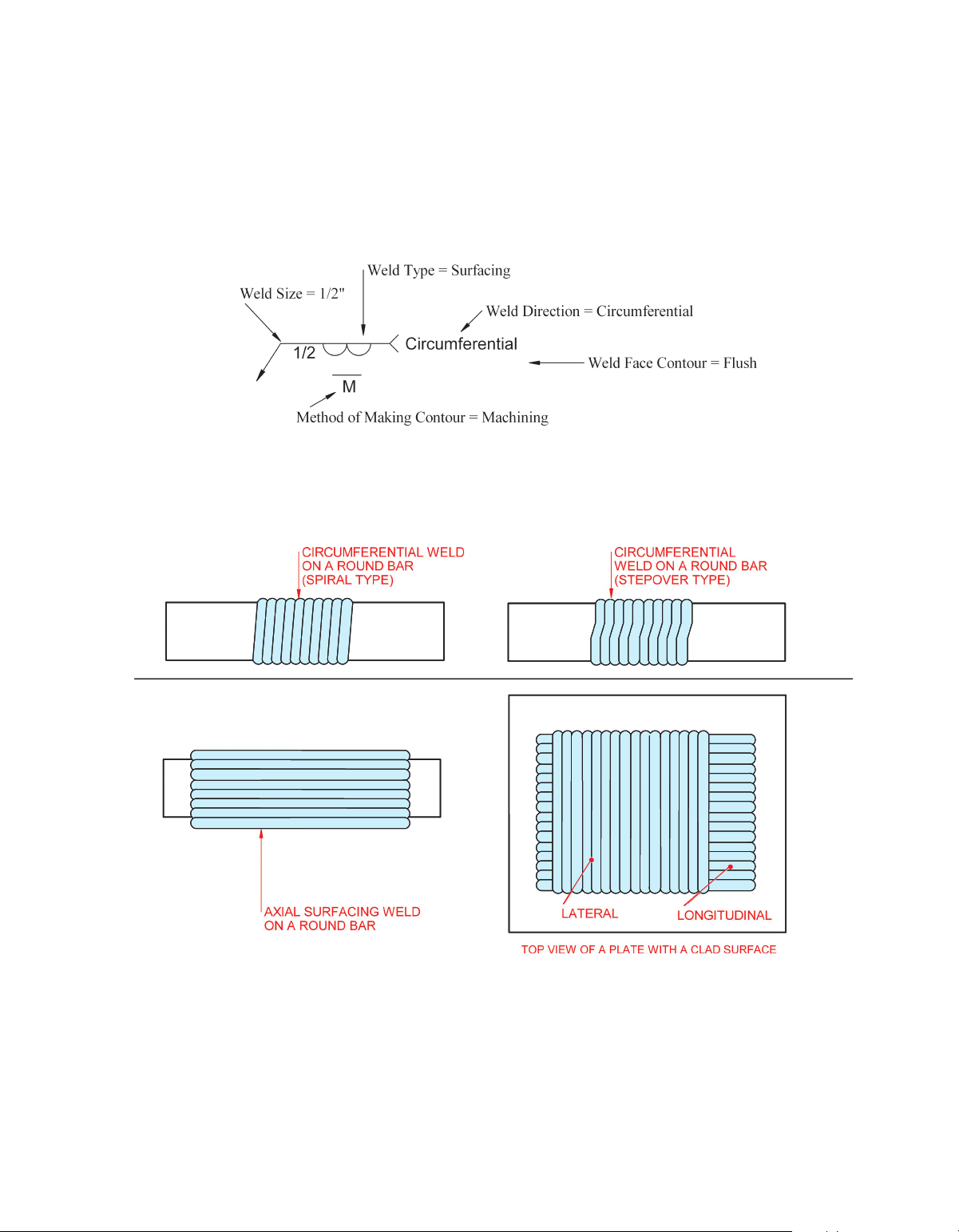
M10_CORG3839_02_SE_C10.indd 164 26/09/15 4:49 pm surFacing weLds
The size of a surfacing weld is determined by its height from the substrate to the
face of the weld. The weld direction of surfacing welds is identified in the tail
of the welding symbol by the terms axial, circumferential, longitudinal, and lateral,
or it may be identified in a welding procedure. See Figure 10-29. Examples of
surfacing weld placement direction are shown in Figure 10-30.
Figure 10-29 Surfacing Welding Symbol
Figure 10-30 Surfacing Welds
advanced Welding Symbols 165
M10_CORG3839_02_SE_C10.indd 165 26/09/15 4:49 pm
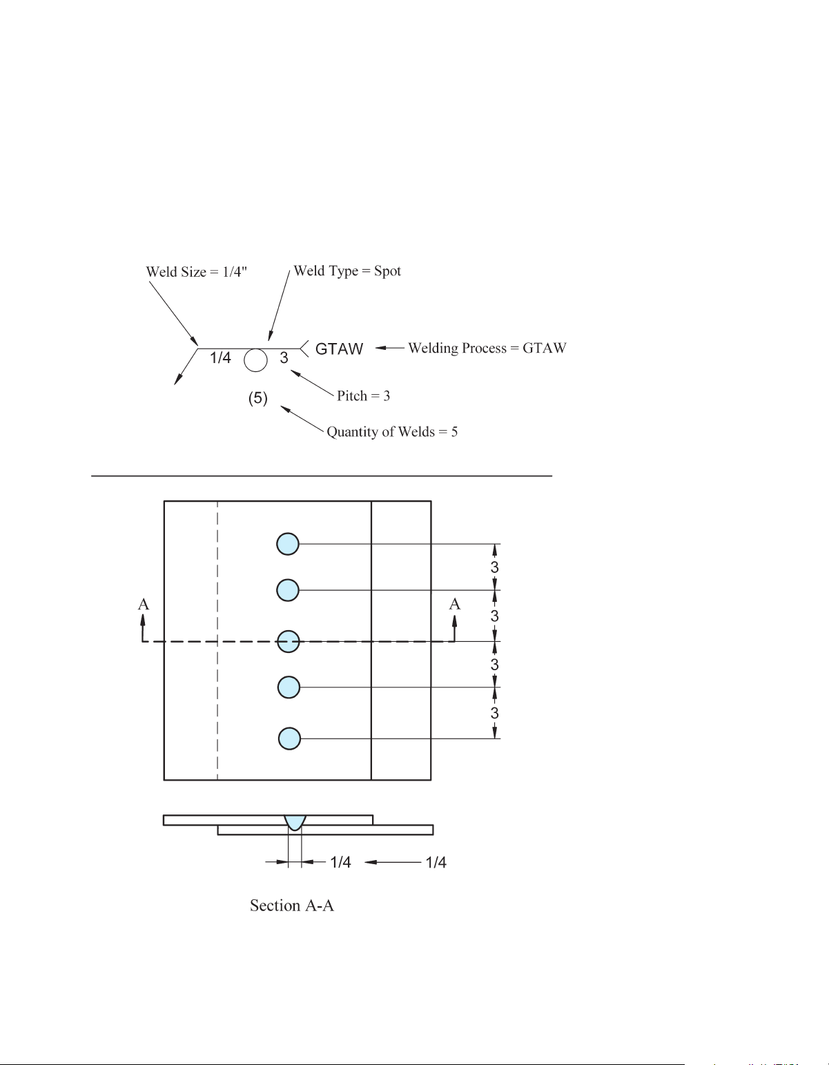
spOT and prOjecTiOn weLds
Figure 10-31 shows how the size, quantity, pitch, and process for spot welds
are depicted. The size refers to the size of the weld at the junction of the faying
surfaces of the materials being joined. Shear strength, given in pounds or new-
tons, may be used in place of the size dimension. There is no length dimension.
As you saw in Chapter 9, the spot weld symbol may be placed on the arrow
side or other side of the reference line, or it may straddle the line to indicate no
arrow side or other side significance. Projection welds use the same symbol,
size, quantity, and pitch designators, except projection welds should be shown
only as arrow side or other side.
Is the Weld Size at the Faying Surfaces
Figure 10-31 Welding Symbol Example for a Spot or Projection Weld 166 Chapter 10
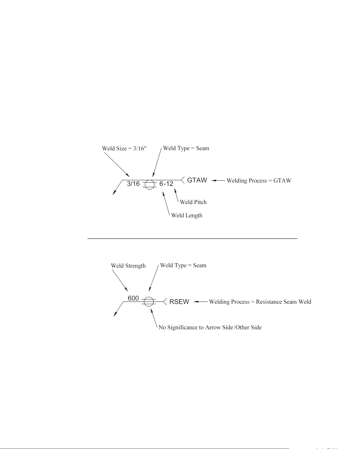
M10_CORG3839_02_SE_C10.indd 166 26/09/15 4:49 pm seam weLds
The seam-welding symbol indicates a weld that takes place between the faying
surfaces of a lap joint that may be composed of two or more lapped pieces. The
weld is done typically by moving the lap joint between two rolling electrical
contact wheels that pass current through the joint to create a type of rolling spot
weld called a resistance seam weld (RSEW), or by a welding process that has
enough arc energy to melt through one of the plates and weld down into the
other(s). Seam welds can be made by making overlapping spot welds to form
a seam. Figure 10-32 shows two different seam welding symbols with supple-
mental information that may be used.
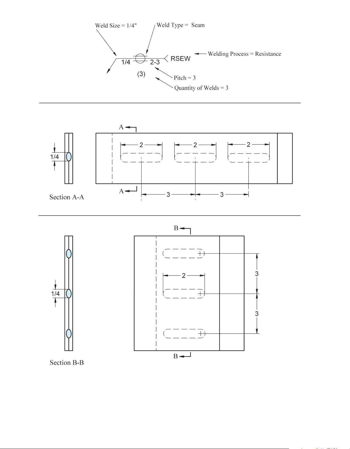
Figure 10-33 shows two different ways that seam welds can be made: end
to end or side by side. End to end is considered the way indicated by the weld-
ing symbol unless a separate detail indicates otherwise.
Figure 10-32 Welding Symbol Example for a Seam Weld
advanced Welding Symbols 167
M10_CORG3839_02_SE_C10.indd 167 26/09/15 4:49 pm
Figure 10-33 Different Configurations for Seam Welds 168 Chapter 10
M10_CORG3839_02_SE_C10.indd 168 26/09/15 4:49 pm
Tài liệu liên quan:
-

Ung dung game hoa trong cac chien dich MKT
27 14 -
Bao cao Chi so TMDT Viet Nam 2025
30 15 -
Thông tư quy định về việc phân quyền, phân cấp và phân định thẩm quyền quản lý nhà nước về giáo dục cho chính quyền địa phương
31 16 -
Nghị quyết về phát huy các giá trị di sản văn hóa gắn với phát triên du lịch bền vững tỉnh Khánh Hòa đến năm 2025, định hướng đến năm 2030
33 17 -
Quyết định phê duyệt Chiến lược phát triển du lịch Việt Nam đến năm 2030
20 10