19 Flight operations management: A comprehensive overview môn Quản trị chiến lược hàng không | Học viện Hàng Không Việt Nam
The role of airline Captain has always been that of ultimate accountability for the aircraft, its passengers and crew, but the role has evolved significantly over the last century since the first pilots carried passengers for reward across Tampa Bay on January 1, 1914.1 Early pilots had perhaps more in common with pioneers than the image attributed to themtoday. Tài liệu được sưu tầm gồm 19 trang, giúp các bạn ôn luyện và phục vụ cho việc học tập, đạt kết quả tốt. Mời các bạn đón xem!
Môn: Quản trị chiến lược hàng không 12 tài liệu
Trường: Học viện Hàng Không Việt Nam 639 tài liệu
Tác giả:


Preview text:
lOMoAR cPSD| 59757093 19 Operating a flight A pilot’s perspective Nathan Mi ler 1.Introduction
The role of airline Captain has always been that of ultimate accountability for the
aircraft, its passengers and crew, but the role has evolved significantly over the last
century since the first pilots carried passengers for reward across Tampa Bay on January
1, 1914.1 Early pilots had perhaps more in common with pioneers than the image
attributed to themtoday. Pilots flew in many cases by the seat of their pants. Reading
Ernst K. Gann,2 one can hardly relate to the modernday commander. Early beginnings
Over many years, aircraft have become more sophisticated, with piston engine power
plants driving propellers in the De Havilland Dove through to the Douglas DC3 and
culminating in the mighty Lockheed Constellation. This gave way to gas- turbine-
powered aircraft in the 1950s with the advent of the ill-fated De Havi land Comet,
followed by the hugely successful Boeing 707. With this sophistication came a number
of fundamental changes for those who commanded and flew these aircraft. Early piston
aircraft were, by modern standards, unreliable; their piston power plants stretching the
limits of the technology of the time, they experienced numerous engine failures and
other mechanical perturbations. Furthermore, systems aboard these aircraft were, by
modern standards, rudimentary. Previous generations of aircraft were literally ‘Fly by
Wire’, with a direct connection between the pilots’ control columns and the control
surfaces, via cables. Aerodynamic design, power, weight and speed a l contributed to
how the aircraft flew and how the pilots interpreted the airc raft through the control columns.
Early navigation and radio communications were conducted by dedicated
professionals, namely the navigator and the wireless operator. Long since forgotten,
these roles were necessary in order to carry out the complex tasks associated with
operating early aircraft wireless communication systems and navigating using maps,
dead reckoning, and celestial navigation. More recently, the retirement of aircraft such
as the Boeing 727 and 747-300 saw the role of flight engineer, the trusted expert tasked
to manage the complex systems associated with modern aircraft, become redundant.
The advent of the Jet Age in the 1950s welcomed in a new era in aircraft
sophistication, speed, size and reliability. Whilst the early Pratt &
WhitneyJT3D- 1 engines of the B707-120B were, by modern-day standards,
underpowered, inefficient and relatively unreliable, these power plants brought with
A pilot’s perspective268
them a new age for air travel. Very quickly, modern technology, fromtransistor to
digital and computer, saw the removal of the flight wireless operator, with this role
now absorbed by the pilots. Next, with the new INS (Inertial Navigation System)
technology, the navigator’s role came to an end with the introduction of aircraft such
as the B747-100. Finally, with the advent of FADEC (Fully Automated Digital Engine
Control), further improved engine reliability, and enhancements such as digital engine
monitoring and displays, the flight engineer was removed in aircraft such as the B747-
400. The cockpit, having been reduced from perhaps five persons, is now a cosy two
(excluding augmented crew operations). Compared to the swashbuckling explorer days
of Ernst Gann, today’s pilots are not expected to discover or learn or ‘pioneer’ – far
fromit. Now, airlines, and by far most of their passengers, expect a flight to be a far
more sombre, calm and repetitiously banal affair.
The modern airline Captain and his crew are tasked with just that: to ensure that the
flight departs on time, avoids even the slightest hint of danger and travels uneventfully
to its destination, where it touches down on time. Sophisticated systems are only part
of the trick to this. Decades of honed procedures, relentlessly trained into skilled
professionals using leading training techniques ensure that the Captain and crew are
able to offer the sound contented monotony which today’s air travel demands. This
chapter will discuss the ways in which the modern airliner and its flight crew come
together in a detailed and intricate systemto performrepeatedly, a complex,
highlysynchronized routine, the result of which is predictably safe, routine and ultimately successful.
Role and responsibility of the Pilot in Command (PIC)
Whilst the intention of this chapter is not to engage in a detailed description of the role
of the PIC, it is, however, necessary to at least bring to life the core legal concerns of the
PICin terms of their day-to-day responsibility:
legal civil aviation legislation, including Civil Aviation Regulations
(CARs) and Civil Aviation Orders (CAOs) safety disposition of the aircraft security. Customer interaction
The modern-day Captains cannot ignore their role in terms of the customer. In general
terms, this has been one area where little demonstrable progress has been made.
Arguably, in the post-9/11 world of locked cockpit doors and heightened security,
modern flight crew are more isolated fromtheir passengers than ever before. Prior to
9/11, many Captains would enjoy inviting passengers into the cockpit or even, for a
lucky few, up for a landing in the jump seat.3 Many an aviation career was born through
a fortuitous invitation to witness a landing from immediately behind the controls. The
interactions between today’s flight crew and the customer are limited to visibility whilst
walking through the terminal and occasionally, time permitting, during disembarkation
in addition to the venerable public announcements (PAs). Today however, the PA must
be carefully considered. PAs prior to departure can be a useful tool to both provide the
A pilot’s perspective269
Captain’s reassurance as well as to convey flight and destination information. These,
however, are made time permitting. PAs during flight are becoming less effective as
passengers are engaged with either their own portable electronic devices, such as
tablets, smartphones, etc., or the aircraft’s in-flight entertainment, in which case, an
unfortunately timed announcement during a critical phase in the movie can irritate,
rather than inform. As the role of the flight attendant has become far more
sophisticated in meeting the customers’ expectations (see Chapter 20), pilots have
lacked this training and in many cases still believe their primary role – to conduct a safe
flight – is sufficient in and of itself.
Initial recruitment and training of pilots
Airline employment programs are typically cyclical, with two key drivers: airline expansion pilot attrition. Airline expansion
Historically, this meant the acquisition of additional airframes, achieving net growth
in fleet size. There can be numerous drivers for this, ranging from commercially driven
opportunities to nationalistic and politically driven ones. Whilst fleet renewal and
replacement can and does create a temporary increase in crew demand, due to the
need for additional crew in training (and therefore not yet operating), overall this is
not a permanent state. More recently, as airlines have sought to increase profitability
and ROIC(return on invested capital), one key lever has been to increase aircraft
utilization. During the period from 2012 to 2016, both Qantas Airways and Virgin
Australia announced increases to fleet utilizations.4 Once any latent crew capacity is
absorbed, further increases to fleet utilization will increase crew demand and therefore recruitment. Pilot attrition
Pilot attrition (pilots leaving the airline) has two core components: resignations retirements.
Whilst a third driver – redundancies – also exists, it is not a recruitment driver.
2.Recruitment of pilots
Airlines, having identified a requirement to recruit, will typica ly commence the
process with a detailed analysis of their crew requirements in terms of crew ranks:
Captains, First Officers or Second Officers. For the majority of established airlines,
pilot contracts force strict adherence to systems such as the North American
Seniority system. As such, new pilots are recruited to the lowest ranks and placed at
the bottomof the list. In exceptional circumstances, such as a lower pool of
A pilot’s perspective270
experience, or immediate demand for experienced crew, these airlines wi l recruit
directly into more senior roles. An example of this in Australia was a Qantas Airways
recruitment campaign in 2001 for direct entry B767 and B737 First Officers to a
leviate the gap created fo lowing the co lapse of Ansett Airlines. Many of the non-
legacy airlines are not constrained by Seniority and wi l therefore seek to recruit
pilots to the positions required. Examples of this include Middle Eastern carriers who
continue to employ experienced Direct Entry Captains.
Airlines wi l set minimum experience criteria associated with the recruitment of
new flight crew. Generally, these requirements are set by the Flight Operations team,
having regard for factors such as the overa l experience levels in the airline,
capabilities of the training system, and simple supply and demand. Aviation Insurers’
requirements can also be a factor in flight crew selection. Having defined overall
numbers required, minimum experience levels and ranks to recruit, the airlines wi l
then be in a position to place advertisements for crew. Fromthere, an initial screening
process will comprise the first cut. This wi l include a review of relevant biodata such
as education and experience levels. There are many different variances on the overa
l themes. However, in general terms, most airlines wi l employ a three-part selection
process post initial screening, which includes: psychometric testing flight testing interview.
Aspiring airline pilots are sourced from four main backgrounds:
general aviation military smaller niche airlines
and charter companies airline-sponsored cadet programs.
Fo lowing initial selection, new recruits wi l enter an intensive training program,
which wi l take place over a period of up to five months or more, depending on initial
aircraft type, the airline’s training system, and recruits’ experience levels. The stages of
training will initially include the ground training elements, such as:
orientation aircraft type technical training (Ground School) systems training flow or
scans training Fixed Base Simulator training Full Flight Simulator training Emergency Procedures training.
Each of the above stages will be assessed, with particular emphasis on the crucial
Full Flight Simulator assessment. Following the ground training elements, recruits will
commence ‘Line Training’, which will consist of a minimum number of sectors. The exact
number of sectors will again vary by airline and pilot experience, i.e., cadets wi l receive
substantially more training. As a guide, First Officers on narrow-body jets will require a
minimumof eighty (checked) sectors, whereas training for other ranks will generate
different requirements. Line training will be conducted by an airline’s qualified Training
A pilot’s perspective271
(or Check) Captains. Following the completion of the minimum sectors required, a final
check will be carried out by a suitably qualified Check Captain. This check is commonly
referred to as the ‘Clearance to Line’, upon successful completion of which a new recruit
is cleared to operate with a line Captain, performing typical line duties.
Recurrent training and checking
In order to maintain quality assurance, ensure continuous improvement and provide
training opportunities for new systems, policies or procedures, airlines wi l schedule
pilots to attend a number of training and assessment sessions in an accredited Level
Dsimulator. The task of training and quality assuring pilots is handled by the airline’s
Training and Checking5 Department, sometimes referred to in Australia as the ‘CAR
217’ in reference to the regulations governing Training and Checking. The CAR 217 wi
l be led by a HoTAC(Head of Training and Checking), whom the Civil Aviation Safety
Authority (CASA) or equivalent national aviation authority (e.g., Federal Aviation
Authority (FAA) in the USA) approve. The HoTACis responsible for the Training and
Checking Department’s policies and procedures, including details of the airline’s pilot
training and checking program (usually a cyclic program), as well as Emergency
Procedures Training and Checking for both Flight and Cabin Crews. This will be
documented in the airline’s Training and Checking Manual, which must be approved
by the Regulator (e.g., CASA or FAA). In regulatory terms, The Civil Aviation Act (or
equivalent) regards the HoTAC as responsible to the Accountable Manager (Chief Executive Officer – CEO).
Once checked to line, all pilots can expect four simulator session days each year.
This can take the form of either a one-day check each quarter, or two days, comprising
a training day and a checking day. The simulator provides an opportunity to practise,
review and repeat specific exercises in a safe and cost effective manner, whilst
simultaneously facilitating a learning environment in which maximum training value
can be extracted. Regulation CAO 82.0 requires the use of Flight Simulator Devices for
aircraft with more than twenty passenger seats. Simulators must be certified as
appropriately representing the aircraft type to an acceptable level of fidelity. Sessions
will normally encompass a range of exercises, as determined by the approved training
matrix, and will usually include a selection of non-normal procedures such as system
malfunctions, as well as emergency procedures (e.g., engine failures and fires).
Flight simulator sessions carry a degree of jeopardy, depending on the airline’s
Training and Checking Department policies. For example, pilots who are unable to pass
a particular exercise after a predetermined number of attempts (usually with retraining
in between) may be let go by the airline. In addition to Simulator Checks, pilots are also
required to pass an annual Line Check, which is an observation of normal operations,
conducted either from the aircraft’s Flight Deck supernumerary, or jump seat, or a
control seat. Finally, both flight and cabin crew are required to attend an Emergency
Procedures (EPs) assessment – for pilots, this is an annual requirement. These
requirements, covered under CAO20.11, ensure that all crew are proficient in such
things as the operation of normal and emergency exits for an evacuation on land and
water, location and operation of on-board equipment, as well as crew duties in an
A pilot’s perspective272
emergency. Both the pilots’ annual Line-Check and the Emergency Procedures training
must be passed and will therefore carry a level of jeopardy, like the simulator checks.
Standard Operating Procedures – purpose and role
Prior to any discussion of a typical airline flight, the concept of Standard Operating
Procedures (SOPs) must be understood. A SOP is a documented set of accurate and
detailed instructions which articulate specific ways to perform a process or procedure.
Their purpose is to ensure that the procedure is performed in a standardized manner,
i.e., the same way, every time by every person. The absence of SOPs would inevitably
lead to well-intentioned individuals performing tasks with degrees of differentiation,
thereby introducing potential risk. Well-communicated and understood instructions
ensure that, irrespective of background and experience, all those performing a task or
procedure do so in the same manner. Much can be said of the background and history
of SOPs. Suffice it to say here that a key learning outcome from aviation accidents has
been that adherence to a set of SOPs provides an effective safety control. The US FAA
defines the scope and contents of SOPs.6 The SOPs defined in AC120- 71 includes items related to:
general operations policies (i.e., non-type-related) airplane
operating matters (i.e., type-related).
Further, AC120-71A lists the mission of SOPs as being ‘to achieve consistently safe
flight operations through adherence to SOPs that are clear, comprehensive, and readily
available to flight crew members’. According to Airbus, strict adherence to suitable SOPs
and normal checklists is an effective method to:
prevent or mitigate crew errors anticipate or manage operational threats; and thus,
enhance ground and flight operations safety.7
Without strict adherence to SOPs, the implementation of good Crew Resource
Management (CRM) practices is not possible. SOPs are recognized universa ly as being
basic to safe aviation operations. Effective crew coordination and crew performance are
two central concepts of CRM, and depend upon the crews having a shared mental
model of each task. That mental model, in turn, is founded on SOPs.
Flight crewpre-flight – up to twenty-four hours prio 3.r Rosters
The nature of most flying operations, particularly RPT (Regular Public Transport),
dictates that the allocation of work to pilots is done via rosters. Rosters are generated
by the requirements of the airline’s schedule and take in to account various factors for the pilots including:
CAOFlight Time Limitations (CAO48.0)
industrial agreements airline
schedule constraints crew fatigue.
A pilot’s perspective273
Pilot rosters are published generally for a 14-, 28- or 56-day period with most crew
being provided their roster at least seven days in advance. The roster will detail all of
their work periods, their days off, standby days and any other duty periods. In
accordance with the regulator’s legislation, the airline is required to roster in
accordance with the Flight Time Limitations (see CAO48.0), as well as to constantly
monitor pilots’ duty and flight times to ensure they are within the legally prescribed limits. Readiness for work
Fatigue has become a more of a feature in recent years, as research and accident history
have shown that the presence of fatigue in a pilot (or indeed any individual) has a
demonstrable effect on their performance. Existing Flight Time Limitations are based on
a prescriptive format which seeks to ensure safe operations through limitations on duty
and flight times – on a per-duty as well as cumulative basis, minimumrest periods,
frequency of late night and ‘back of the clock’ operations and other such limitations. In
contrast, a focus on fatigue aims to understand the underlying impact of the work being
performed, together with quality of rest and individual factors in order to gauge and
predict an individual pilot’s ability to perform the rostered duty safely and within
acceptable limits of mental alertness. In the lead up to a pilot’s duty, careful
consideration needs to be given to managing rest appropriately to ensure that any flight
duties can be performed with the highest levels of mental alertness, thereby helping to
avoid fatigue-based errors. Regional and low-cost airline pilots, in particular, can find
balancing the repetitious nature of their flying, with many days on- duty, and ability to
ensure quality rest in the home environment with all of the ensuing distractions,
challenging. It could be argued that the practice of multi-day trips, more common in fu
l-service airlines which employ optimum ‘customer driven’ schedules, can facilitate a
more consistent and undisturbed rest period, particularly for those pilots with a family life at home. .Arrival at the airport
Pilots will arrive at the airport at or prior to ‘Sign-on time’, the time that they are
required to report for duty. At their home or at major ports, this will generally be in a
crew room, where the company will provide the necessary facilities for their pre-flight
preparation. Duties performed at sign-on will commence with obtaining the company-
supplied briefing material, which includes:
Flight Standing Orders, INTAPs (Internal Notice to All Pilots), MELs (MinimumEquipment Lists) weather
NOTAMs (Notice to Airmen) flight plans.
Most airlines now provide mobile solutions for documentation and manuals, held
and presented on tablets such as iPads. Pilots will therefore be required to ensure that
the documentation and programs held are the most recent version.
A pilot’s perspective274
The crew will gather the required information and then review it individually. Then,
in accordance with good CRM practice, they will then discuss what they have observed.
Ultimately, the crew is seeking to make informed flight planning and fuel decision, taking
into account the serviceability of the aircraft itself (and any MELs) and any restrictions
that may impact their operations. This could also relate to the nature of the destinations
themselves and any restrictions on them such as runway closures or airspace limitations
as advised by NOTAM, and any weather, both en route and at the destination. The
weather in particular will play a part in influencing the ultimate fuel decision.
The presence of thunderstorms over a destination or the need to plan for an alternate
airport will place a requirement for the aircraft to carry up to an additional sixty
minutes of fuel. The consequence of this additional fuel may result in commercial
penalties (cost) and/or operational requirements (possible offload of passengers or
freight, or even rerouting of the flight). At the conclusion of the Pre-Flight Briefing,
the crew will decide, the Captain having the ultimate decision authority, on an
appropriate fuel figure, and this will be passed to the company and the refuellers.
Completion of Flight Planning also serves as a suitable time to decide which pilot
will be the Pilot Flying (PF) on particular sectors and which pilot will be the support
pilot or Pilot Monitoring (PM). In simple terms, the PF will be responsible for flying the
aircraft, either using the autopilot or manually through the aircraft’s joystick or control
column, whilst the PM will support the PF with tasks such as checklist ca ling,
secondary control selection (flaps, landing gear, etc.), radio operation, to name a few.
Either pilot can be PF or PM, however the Captain will always be ‘in charge’. Ultimately,
the Captain will decide, taking into account factors such as crew experience, weather,
aircraft serviceability and airport restrictions, etc., as it is the Captain who is legally
responsible for the disposition of the aircraft, its passengers and crew.
PICpre-flight briefing to cabin crew
Having reviewed all the relevant information to the day’s flying, the Captain (or
delegated flight crew member) wi l conduct a briefing to the cabin crew. This briefing
can be to the entire crew, typical in smaller narrow-body aircraft, or to the Cabin
Manager and/or deputy in the case of larger aircraft, who will in turn, brief the
remaining crew. This is an opportunity to provide operational information to the cabin
crew, and to gain understanding of any issues from their perspective. It also helps to
build rapport as a basis for sound CRM. An example of the type and format of
information passed on is the ‘ISTOP Threats’ format below: I Introduction
S Status of the aircraft (any relevant MELs) and to confirm crew is ‘fit to fly’ T Turbulence/weather
O Operational considerations such as, for example, boarding via rear stairs, curfew considerations P Passwords
Threats Any threats not identified above, along with mitigation strategies.
A pilot’s perspective275
Once the cabin crew briefing is complete, the pilots wi l proceed to the flight deck. Flight deck preparation 4.
Initially, a preliminary cockpit preparation is completed to ensure that the flight deck
(cockpit) and aircraft are in a suitable initial state to commence set-up. This wi l start
with abasic safety check prior to the continuation of set-up procedures and wi l include
items such as the positioning of important switches and levers such as landing gear (and
pins), seat belt sign position (e.g., ‘OFF’ during refue ling), etc. The Captain will also
conduct a review of the aircraft’s serviceability which wi l include a review of the
maintenance or technical log. Following the preliminary preparation, each pilot will
continue with their own tasks. These tasks wi l be dependent on whether that pilot is
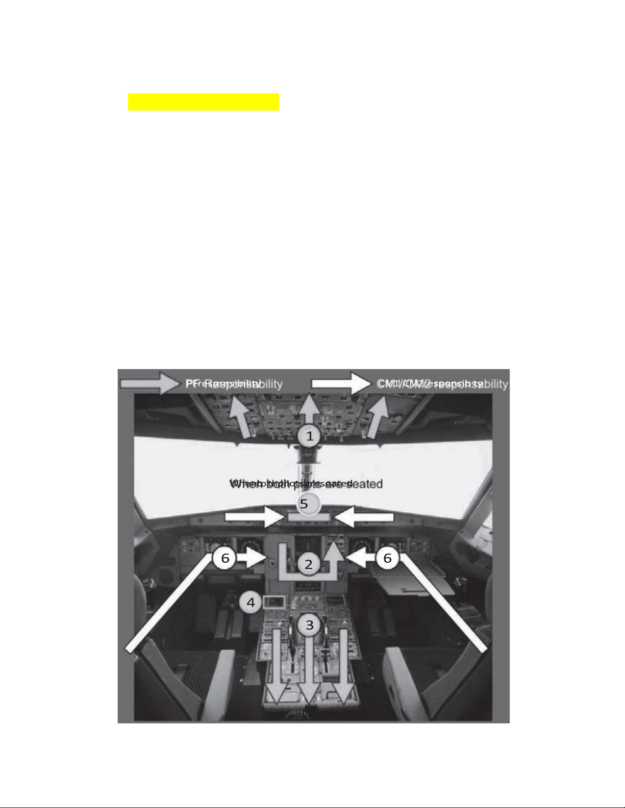
Flying (PF) or Monitoring (PM). Like most of the normal procedures from this point on,
the pilots will fo low a ‘scan’ or ‘flow’ pattern which wi l define the order in which they
performtheir tasks. An example of a cockpit preparation flow pattern is presented in Figure 19.1.
4.Flight Management System set up
It is worth mentioning here the importance and programming of the Flight
Management System (FMS). The FMS is an essential component of the
Figure 19.1 Cockpit preparation flow pattern
A pilot’s perspective276
modern airliner and is a dedicated computer systemwhich performs numerous aircraft
functions including navigation, performance, and aircraft operations. The heart of the
FMS is a computer ‘brain’ (Flight Management Computer or
FMC), and a number of display units, MCDUs (Multifunction Control and Display Units)
or DUs (Display Units), which the pilots will use to program the FMS. The FMS
automates a large number of tasks which would previously have been performed by a
flight engineer or navigator. The FMS comprises four main components: an FMC
the Automatic Flight Control Systemor Automatic Flight Guidance System (AFCS or AFGS)
the Aircraft Navigation System anElectronic Flight
Instrument System(EFIS) or equivalent instrumentation.
Aircraft navigation is a primary function of the FMS. Utilizing Global Positioning
System(GPS) and Inertial Reference System(IRS) inputs, the FMS calculates aircraft
position and maintains Flight Plan track when required. The FMS sends this information
for display to the EFIS, Navigation Display (ND), or Multifunction Display (MFD). Given
the importance of the FMS, accurate programming is essential. Other essential checks
that will be performed prior to each and every flight are first, the exterior walk around,
where a Flight Crew member conducts an external check of the aircraft, its critical
components and systems, and second, the oxygen check procedure, where each
operating crew member will ensure that his/her crew station oxygen mask is operating
correctly. This is essential in the event that the aircraft experiences a decompression.
During this preparation, once any required refue ling is complete, the fuel system will
be checked, correct gauge quantity independently verified, and the seat belt sign
ensured to be in the ‘on’ position. It is at this point, where all necessary programming
and checks have been completed by each individual pilot, according to the requirements
of their function (PF or PM) that the Flight crew will come together for the first time in
the aircraft and verify each other’s critical inputs as well as forming a ‘united crew
understanding’ of the flight. Checks and briefings
The final checks and briefings will be conducted at an appropriate stage prior to
departure. Items discussed will include:
aircraft status and serviceability fuel quantity and checks flight plan check
Airways Clearance request and check briefing aircraft data check. Flight plan check
This is a check that the flight plan, as discussed at pre-flight briefing, has been correctly
entered into the FMS and that the FMS data matches the ‘paper’ flight plan data (i.e.
with respect to waypoints, distance, etc.). This is a critical function for aircraft
A pilot’s perspective277
navigation, as the information carried in the FMS represents the direction that the
aircraft will designate the pilot, or autopilot to fly. An incorrect entry may place the
aircraft in a potentia ly dangerous conflict scenario. This check is conducted by both pilots.
Airways Clearance request and check
The PM wi l request an ‘Airways Clearance’ via the radio and record the information.
This will then be confirmed as correctly set in the FMS, that the correct cleared altitude
is set in the aircraft’s ‘altitude window’ instrument, and that the correct transponder
code is set. This wi l be verbally read back by the PF, and verba ly cross-checked by the PM. Briefing
The briefing is critical to ensuring that all flight crew share a common understanding of
the intended flight path, method and modes of operation proposed for the aircraft – in
other words the plan of action. The briefing is normally performed by the PF. However,
it may be permitted to delegate it to another flight crew member when considered
appropriate. There are various forms that the briefing may take. Many airlines do not
specify a structure, but all will specify a minimum content. Pushback and engine start
Once all the checks, briefings and required cabin preparations are complete, the crew
wi l complete the ‘Before Start Checklist’. If the aircraft is parked in a position where it
is required to push backwards prior to taxi, then a ‘pushback clearance’ will need to be
obtained. Once engine start and pushback (if required) are complete, the crew will
commence another scan to ensure that the aircraft is now set to the required
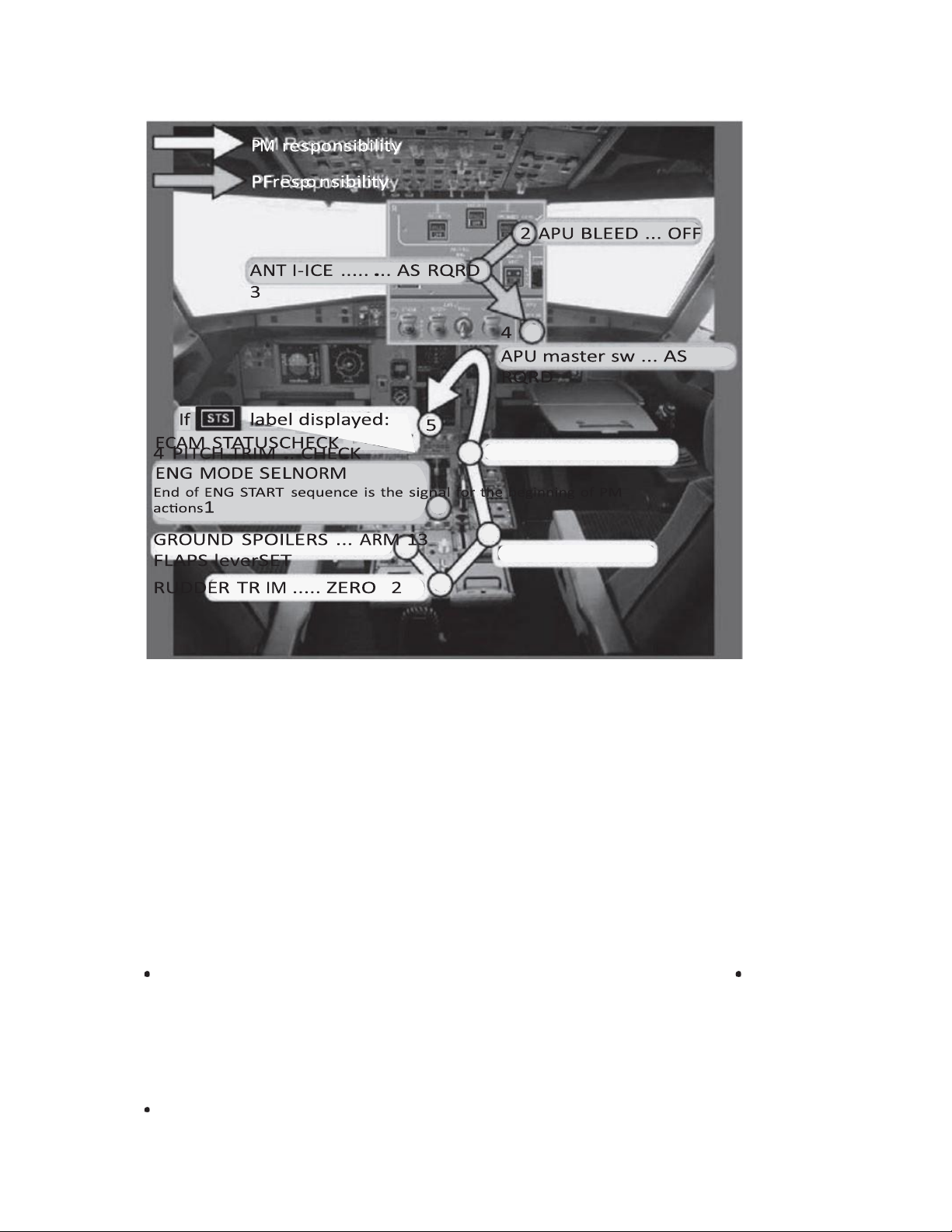
configuration. This may differ by type. For example, the Airbus type aircraft will at this
point be configured for the take-off configuration, as per the example in Figure 19.2.
Once the scan is complete, the PM will request a taxi clearance (usua ly) from Air
Traffic Control (ATC) and the PF will taxi the aircraft to the cleared position. In most
aircraft over approximately thirty seats, this will be using a small tiller positioned near
the Captain’s left hand (First Officer’s right hand if a second tiller is fitted). During the
aircraft’s taxi to the take-off position, the cabin crew will complete the passenger
briefing whilst the flight crew will complete any required ‘Pre-take-off ’ checklists. The aim is to have all crew
A pilot’s perspective278
Figure 19.2 Take-off configuration flow pattern
checks completed by the time the aircraft reaches the holding point such that the crew
can advise the Control Tower that they are ‘Ready’ for takeoff. 5Sterile flight deck policy
To minimize crew distraction and ensure that both pilots are focused on the critical flight
operations, a sterile cockpit policy limits conversation/comments, etc. to matters
directly relating to the operation of the aircraft during the fo lowing periods:
on departure, from last door closed until the seat belt sign is switched off
on descent, from transition level8 (e.g., 11,000 ft in Australia, 18,000 ft in US airspace)
until the aircraft arrives at the gate.
Furthermore, most airlines will incorporate policies restricting cockpit contact by
cabin crew, generally during the following periods:
take-off – limited contact between door close to application of take-off
A pilot’s perspective279
thrust; no contact from take-off power application to landing gear retraction landing –
limited contact fromcommencement of descent or passing 20,000 ft to landing gear
extension; no contact between landing gear extension to end of the landing roll. Take-off and climb Take-off
Upon receiving take-off clearance, the crew will complete any remaining checklist items,
confirm that they are entering or on the correct runway, check any critical settings, then
commence the application of power. Most modern transport aircraft engines (jet and
turboprop) use FADEC to control the engines. FADEC is effectively ‘fly by wire’ for the
aircraft thrust levers (for jet aircraft) or power levers (for turboprop aircraft). FADEC
ensures that the application of power through the levers will result in the desired thrust
being developed by the engines without exceeding any limitations (e.g., temperature/
torque). FADEC’s introduction in the 1980s was an important feature used to reduce
crew workload managing engines, particularly during critical phases of flight, and
therefore enabling the reduction of crew complement such as the flight engineer. Whilst
the PF will move the thrust levers initially, at some point, the FMS (for aircraft fitted with
this) will ‘take over’ the fine-tuning of power, ensuring that the preprogrammed thrust
settings are achieved. Simultaneously the PF wi l use the aircraft rudder pedals to guide
the aircraft down the runway to the takeoff speed and rotation point. The PM will
monitor the correct engine and other instrument settings, aircraft systems and tracking.
At this point, some explanation of ‘V’ speeds is required. V speeds are standard terms
given to defined airspeeds critical or important to the aircraft’s operations. Whilst there
are numerous V speeds used, for the purposes of simplicity, only the most useful for the
take-off manoeuvre are shown below: V1(pronounced Vee one) VR V2.
These are explained according to definitions provided below by Airbus.9 V1: Decision speed
V1is the maximumspeed at which a rejected take-off can be initiated in the event of an
emergency or as required by ATCor the pilots. V1is also the minimum speed at which a
pilot can continue a take-off after an engine failure. If an engine failure is detected
after V1, the take-off must be continued. This implies that the aircraft must be controllable on ground. VR: Rotation speed
The rotation speed ensures that, in the case of an engine failure, lift-off is possible
and V2is reached by a height of 35 feet (ft) at the latest. (Note: therefore, at 35 ft, the
A pilot’s perspective280
actual speed is usually greater than V2.) The rotation of the aircraft begins at VR , which
makes lift-off possible at the end of the manoeuvre.
V2: Take-o f safety speed
V2is the minimumspeed that needs to be maintained up to acceleration altitude, in
the event of an engine failure after V1. Flight at V2ensures that the minimum required
climb gradient is achieved, and that the aircraft is contro lable. V2speed is always
greater than VMCA (Velocity Minimum Control Air – that is, the lowest speed
directional control can be maintained in the air), and facilitates control of the aircraft in flight.
As the aircraft accelerates, it will achieve V1speed first, from which point there is
no longer discretion to reject the take-off, so the crew will resolve any failures or
abnormalities only when airborne. To signify this, the Captain, whose right hand
remains on the thrust levers up to V1, will then remove it from the levers. This is to
prevent uncertainty of continuing the flight. An audible call wi l be made at this speed,
simply with the PM stating ‘V1’.
At the speed of VR , another call wi l be made of ‘rotate’ and the PF will commence a
steady pu l force on the controls, pitching the aircraft up at a rate of three degrees per
second. Depending on the aircraft type, thrust settings, etc., the final pitch angle wi l
norma ly be around thirteen to seventeen degrees nose up. As the aircraft moves away
from the runway, the PF wi l ca l for the landing gear to be retracted, and as the aircraft
reaches a safe height, or ‘acceleration altitude’ of around 1,000–3,000 ft, the flaps wi l
be retracted. As the aircraft accelerates to climb speed, a scan wi l be performed by the
pilots to ensure that the aircraft is in the correct climb configuration, and the ‘After-take-
off ’ checklist wi l be performed. Climb
As the aircraft continues its climb, the crew will be given a series of clearances from
ATC, for both altitude changes and for tracking, eventua ly clearing the aircraft to its
planned cruising level. At ‘Transition’ the crew will set the aircraft’s altimeters to a
standard setting of 1,013 hPa (hectopascals) thereby ensuring vertical separation
standards are maintained with aircraft in their vicinity. During the climb, crew
workload begins to reduce, such that the crew wi l turn their focus primarily to
navigation and weather updates for both the destination and alternates, as well as
any en-route weather considerations. Once the seat belt sign is switched off, the
cabin crew will commence service and passengers may move around the cabin. This
also signifies to the pilots that they will need to apply additional consideration to
turbulence and the possible reactivation of the seat belt sign. 6.Cruise
With the aircraft entering the cruise phase, the aircraft’s systems wi l conduct the
performance and navigation functions as programmed. The role of the pilots is then to
monitor systems and confirmthat the aircraft is flying according to plan, and act
accordingly if not. This may include navigational adjustments for winds, track shortening
or rerouting to avoid severe weather such as thunderstorms. The crew may also climb
A pilot’s perspective281
(or descend) in order to better optimize performance or to avoid turbulence. They wi l
also maintain communications with ATC, either through Very High Frequency (VHF) or
High Frequency (HF) radio, satellite phone or datalink. During this phase the crew will
continue to monitor weather at the destination and alternates. Descent
As the aircraft approaches approximately 180 nautical miles (NM) from the destination,
the crew will commence final preparations for descent and approach. The preparations
will commence with the crew obtaining the weather information for the destination,
from a service known as the ATIS (Automated Terminal Information Service). This wi l
be obtained either through the VHF radio, electronica ly via the Aircraft
Communications Addressing and Reporting System (ACARS), or broadcast via a
navigational aid at the airport. They may also gather information on any alternates
nearby. Where the arrival airport is ‘uncontrolled’, meaning that there is no Air Traffic
facility, weather information may be obtained via AWIS (Automated Weather
Information Service). Similar to the activities in the departure phase, modern transport
category aircraft are designed to a low the crew to preprogram as much information as
possible into the aircraft’s Flight Management System. This will include the approach
routing, or STAR (Standard Terminal Arrival Route), the approach method, be that either
a visual approach (by sight) leading to a circuit or an instrument approach, and of course
the runway to be used. In most modern transport categoryjet aircraft, the FMS can also
be set up to include information about an alternate runway and approach.
Also programmed will be all necessary data to give appropriate landing speeds,
including aircraft configuration (flap setting), and winds on descent and at the
aerodrome. The above information will normally be programmed in anticipation of an
ATCclearance. Once this is obtained, the crew will verify the entries into the FMS as
correct. By programming in advance, the crew are relieved of some of the workload
which would otherwise be experienced in the busiest part of the descent and approach.
Once a l the programming is complete and the clearance is obtained, the crew will
commence a briefing. Similar to the departure briefing, the aim of the arrival briefing is
to ensure that all crew members have a shared mental model of the intended approach
and landing as well as any likely threats and contingency plans. The briefing also serves
as a valuable opportunity to cross-check the programmed plan against the briefed plan.
The briefing will normally be performed by the PF.
Finally, when within radio range, the crew may seek to obtain from the company
representatives at the airport information such as gate number and details of the
aircraft’s next flight. Modern jet transport aircraft descents follow a similar pattern. At
the calculated descent point, the engine thrust will be reduced to idle and the aircraft
wi l commence a controlled gliding descent. As a rough rule of thumb, modern jet
aircraft descend approximately 3 NM per thousand feet. Adding approximately 20 NM
for deceleration, a typical jet flying at 35,000 ft will commence descent at approximately
135 NM. Various factors may have some effect on this distance, including aircraft weight
and winds. Descent speeds will vary, but a speed of about 280 knots is a general guide.
In contrast, modern turboprop aircraft will also reduce power for descent, however not
to idle. Therefore, their descents will be somewhat shallower.
A pilot’s perspective282
At some pointjust prior to, or during the descent, the crew will notify the cabin
crew of the need to commence preparing the cabin for landing. As the aircraft
approaches 11,000 ft (transition level in Australia), the crew will commence the scans
for the approach checklist. This will include activation of the seatbelt signs, landing
lights and, in Australia, the setting of the aerodrome QNH (a Q code representing
atmospheric pressure, adjusted to sea level at a particular station). The crew will then
normally conduct a checklist to confirm these actions are complete. By 10,000 ft the
aircraft will normally be slowed to 250 knots. In most jurisdictions, this is a maximum
speed for operations below 10,000 ft. As the descent continues, the crew will be in
continuous contact with ATCin the case of a contro led airport, or listening and
communicating on the Aerodrome’s CTAF (Common Traffic Advisory Frequency) at an
uncontrolled aerodrome. At around 20 NM to touchdown, the aircraft should be
approximately 5,000 ft above the airfield and will commence a deceleration to the
approach speed. This deceleration will be continuous, with the crew aiming to have
the aircraft at 210 knots or less by 3,000 ft, with 10 NM to run to touchdown. Landing
The point of 10 NM and 3,000 ft marks the significant point of entry for most approaches
to land. It is by this point that the crew wi l have commenced configuration for landing.
This wi l include at least the first stage of extending flaps, as we l as further deceleration.
The aimis to achieve a continual descent towards a stable approach and landing. The
stable approach refers to a situation whereby the aircraft is fu ly configured, i.e. landing
gear extended, flaps set for landing, engines set for the correct thrust and the aircraft
at the landing speed and descending at an appropriate rate, a l by 1,000 ft above the
aerodrome. The theory, based on numerous studies into aircraft accidents by
organizations such as the Flight Safety Foundation, is that an aircraft flown in a stable
approach wi l have far less chance of a landing incident, such as a runway overrun, or
the need to conduct a go-around, where the aircraft aborts the landing, and positions
again for a subsequent approach.
By at least 1,000 ft, the crew should have completed all instrument scans required
for landing, as well as the landing checklist itself. By 500 ft, the crew wi l typica ly make
a final ca l on the stable approach, ensuring that the aircraft remains stable. In the event
that this no longer remains the case, the crew must conduct a go-around. For the final
1,000 ft, the pilots will continue to fly the aircraft towards the runway, following either
a visual guidance system located on the runway, known as a PAPI (Precision Approach
Path Indicator), or fo lowing an electronic ‘glide path’ indicated in the cockpit. Generally
speaking, for approaches being flown in visual conditions, i.e. where the pilot can see
the runway from at least 1,000 ft, the pilots may elect to disconnect using an autopilot
and manually fly the aircraft from this point on. For most runways in Australia,
depending on the accuracy of the instrument approach being flown, the pilots will need
to disconnect the autopilot by somewhere between 750 and 200 ft. Whilst many aircraft
are equipped with auto-land systems, in Australia the opportunity to use these systems
is limited in poor weather, due to limitations in the physical airport environment.
As the aircraft approaches the runway, at around 30 ft the PF, using visual cues from
the runway markings and environment, wi l manipulate the aircraft to reduce airspeed
A pilot’s perspective283
by gently raising the nose and holding the aircraft (the flare) at a particular attitude for
touchdown. Various corrections wi l need to be made to adjust for wind and other
atmospheric perturbations. Just after the aircraft main wheels touch down, braking
will commence, either through the aircraft’s autobrake system or manually by the PF,
and the aircraft reverse thrust system and spoilers on the wings will be deployed. The
aircraft wi l be slowed to taxi speed, the reversers stowed and ATCcontacted for
further instructions as the aircraft commences the taxi to the gate. Taxi to gate 7.
As the aircraft taxis to the gate, the crew will again perform scans to ‘clean the aircraft
up’ by raising the flaps and configuring the aircraft to taxi. This wi l include starting the
Auxiliary Power Unit (APU), to enable electrical power and air conditioning once the
aircraft’s main engines are shut down. As the aircraft approaches the gate, the Captain
will either be marshalled or follow an electronic guidance system to the correct parking
position. Once parked, engines will be shut down and a further scan and checklist
performed. Any unserviceabilities wi l be entered into the aircraft’s maintenance log
and engineers contacted as required for rectification. At this point the crew will either
commence preparations for a further sector or complete their duties and exit the
aircraft. Crew completing their duties will be given a sign-off period of fifteen to thirty
minutes to allow for completion of all duties. The completion of this period will mark
the end of their duty period, which will be added to their previous periods to ensure
that the crew member continues to operate within the legal limits of flight and duty times.
Glossary of acronyms and abbreviations ACARS
Aircraft Communications Addressing and Reporting
System AFCS Automatic Flight Control System AFGS Automatic Flight Guidance
System APU Auxiliary Power Unit ATC Air Traffic Control ATIS
Automated Terminal Information
Service AWIS Automated Weather Information
Service CAO Civil Aviation Order CAR Civil Aviation Regulation CASA Civil Aviation Safety
Authority CEO Chief Executive Officer CRM Crew Resource Management CTAF Common Traffic Advisory Frequency DU Display Unit EFIS Electronic Flight Instrument
System EPs Emergency Procedures FAA Federal Aviation Authority FADEC
Fully Automated Digital Engine
Control FMCFlight Management Computer
A pilot’s perspective284 FMS Flight Management System ft foot or feet GPS Global Positioning System HF High Frequency HoTAC Head of Training and Checking hPa hectopascal INS Inertial Navigation
System INTAP Internal Notice to All Pilots IRS Inertial Reference System MCDU
Multifunction Control and Display Unit MEL Minimum Equipment List MFD Multifunction Display ND Navigation Display NM Nautical Mile NOTAM Notice to Airmen PA Public Announcement PAPI Precision Approach Path Indicator PF Pilot Flying PIC Pilot in Command PM Pilot Monitoring ROIC return on invested capital RPT Regular Public Transport SOP Standard Operating Procedures STAR Standard Terminal Arrival Route V1 Decision speed V2 Take-off safety speed VR Rotation speed VHF Very High Frequency VMCA Velocity MinimumControl Air Notes
1 Smithsonian – National Air and Space Museum (2007) America by Air (Online) available at
https://airandspace.si.edu/exhibitions/america-by-air/online/early_years/
early_years01.cfm. Accessed 28 June 2017
2 Gann, Ernest K. (1986). Fate is the Hunter. Simon & Schuster, USA
3 Jump seat – an additional seat provided in the cockpit, usually behind and between the
pilots, fromwhich the crew’s actions can be observed 4 Company Annual Reports
5 The term Training and Checking is used for consistency, but may also be known as
‘Checking and Training’ or ‘Check and Training’
6 Advisory Circular (AC) 120-71
A pilot’s perspective285
7 Airbus FOBN (Flight Operations Briefing Note): FLT_OPS – SOP – SEQ 01 – REV 04 – SEP. 2006
8 Transition level in Australia is 11,000 feet for descending aircraft transitioning from Flight
Levels to Altitudes (and setting local QNH), but 10,000 feet for climbing aircraft transitioning
from Altitudes to Flight Levels (and setting the standard atmosphere of 1,013 hPa)
9 Airbus FOBN (Flight Operations Briefing Note): FLT_OPS -TOFF_DEP-SEQ07 -REV01-AUG. 2004
Tài liệu liên quan:
-

okhhghfdgzgvfkfgfdcjhgjjxdhgcfjs
14 7 -

Qualities of Effective Negotiators môn Quản trị chiến lược hàng không | Học viện Hàng Không Việt Nam
37 19 -
Case study: Safety concerns after airport accident môn Quản trị chiến lược hàng không | Học viện Hàng Không Việt Nam
140 70 -

Phân khúc khách hàng và quản trị doanh thu trong hàng không môn Quản trị chiến lược hàng không | Học viện Hàng Không Việt Nam
128 64 -
Tài liệu Chuẩn bị buồng lái và hệ thống quản lý bay môn Quản trị chiến lược hàng không | Học viện Hàng Không Việt Nam
140 70