AlphaBot User Manual - Robot dò đường | Trường Đại học Bách khoa Hà Nội
AlphaBot requires kits: AlphaBot-Ar-Basic, AlphaBot-Ar-Bluetooth, Alpa control board, Arduino OR Raspberry Pi, if you don't have one in hand, please consider the all-in-onehaBot-Pi AlphaBot-Pi Acc Pack requires the control board Raspberry Pi, if you don't have one in hand, please consider the all-in-one kit: AlphaBot-Pi.
Môn: Cấu trúc dữ liệu và giải thuật (ET2100) 143 tài liệu
Trường: Đại học Bách Khoa Hà Nội 5.5 K tài liệu
Tác giả:


Preview text:
AlphaBot User Manual share awesome hardware AlphaBot User Manual Feb. 2017 V1.2 1
Downloaded from www.Manualslib.com manuals search engine AlphaBot User Manual share awesome hardware To the Reader Selection Guide
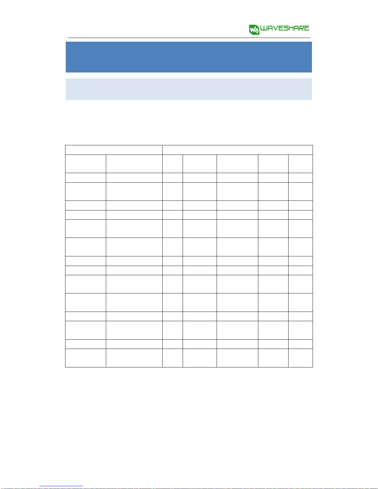
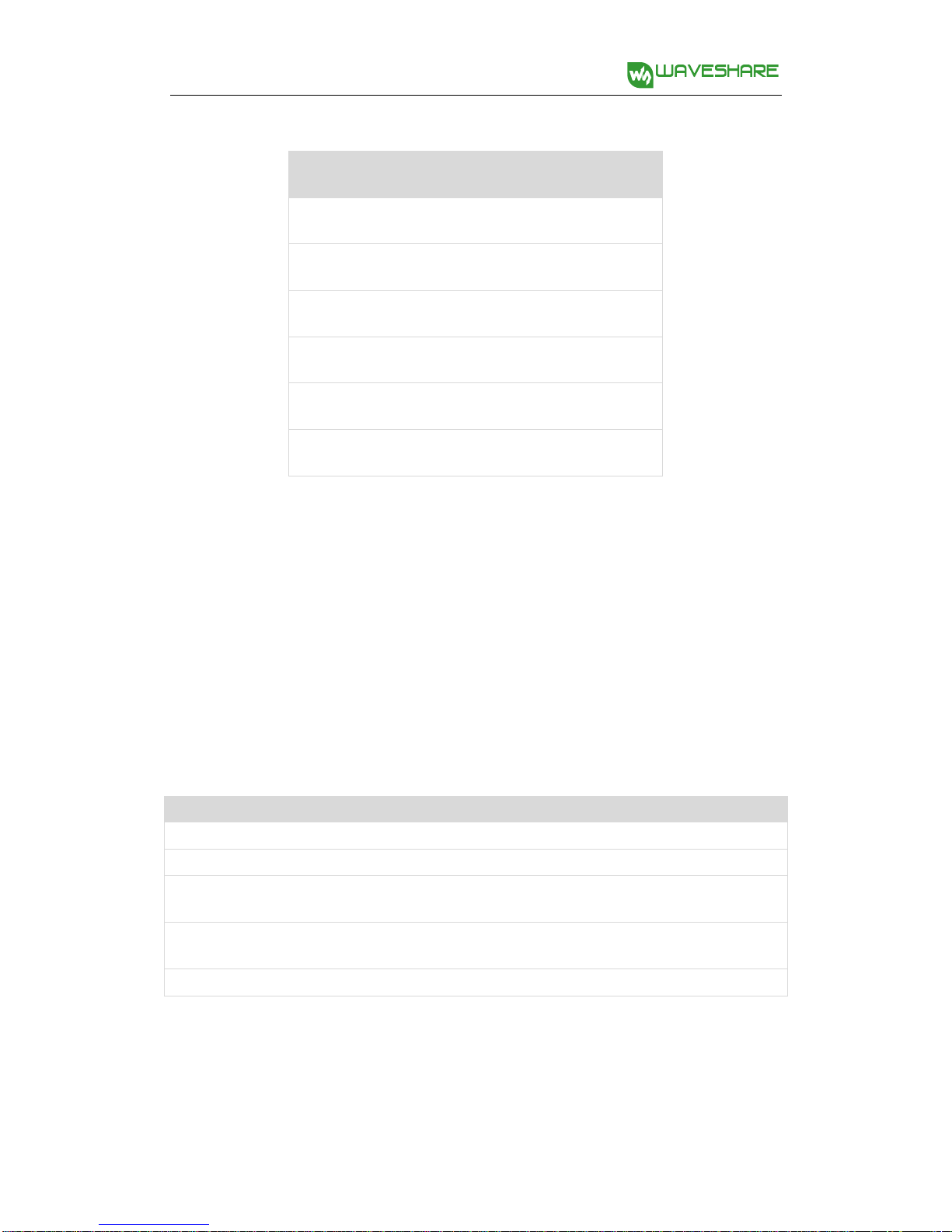
Note: Accessories may be different in different product package. This manual describes all the
compatible accessories but perhaps the product you bought doesn’t contain some of them. The
figure below shows most the compatible accessories: Package Contents Products Item Description AlphaBot AlphaBot-Ar-Basic AlphaBot-Ar-Bluetooth AlphaBot-Pi AlphaBot-Pi Acc Pack RPi3 B Raspberry Pi 3 Model B √ UNO PLUS enhanced control board, √ √ Arduino compliant AlphaBot chassis kit
mainboard, wheels, drivers, etc. √ √ √ √ √ Tracker Sensor line tracking module √ √ √ √ √ Photo Interrupter speed measuring module (2pcs) √ √ √ √ √ Sensor Infrared Proximity obstacle avoidance module √ √ √ √ √ Sensor (2pcs) IR remote controller remotely control the robot √ √ √ √ √ SG90 servo √ √ √ √ Ultrasonic sensor
ultrasonic obstacle avoidance, √ √ distance measuring Accessory Shield accessories add-on board, √ Arduino compliant Dual-mode Bluetooth dual-mode Bluetooth module √ RPi Camera (B)
Raspberry Pi camera, adjustable √ √ focus Micro SD Card 16GB 16GB Miro SD Card, class 10 √ √ 5V 2.5A Power RPi3 B requires 2.5A or above √ √ Adapter power supply Note:
AlphaBot requires a control board, Arduino OR Raspberry Pi, if you don't have one in hand, please
consider the all-in-one kits: AlphaBot-Ar-Basic, AlphaBot-Ar-Bluetooth, AlphaBot-Pi
AlphaBot-Pi Acc Pack requires the control board Raspberry Pi, if you don't have one in hand,
please consider the all-in-one kit: AlphaBot-Pi. 2
Downloaded from www.Manualslib.com manuals search engine AlphaBot User Manual share awesome hardware Recommendation
Reading this document can be a challenge for a freshman. We advise that the
reader need to have some knowledge of the programming in Raspberry Pi Python
or Arduino, which can be helpful for understanding the programming
fundamentals. Due to space constraint, only a few of the programming
fundamentals can be explored here. If you want to have a thorough understand of
them, please check the source code. Here, we will describe more about the practical
experience of smart robot development. Raspberry Pi tutorial:
http://www.waveshare.com/wiki/Raspberry_Pi_Tutorial_Series
Due to the electrical characteristic limitation, user should be more roboteful to use
this product in a safe and correct matter, to prevent the Raspberry Pi board or
Arduino board from irreversible damage by the smart robot chassis. For your first
time in using this product, please follow the steps described in the document. Get details
Waveshare Wiki provides detailed data of AlphaBot, including user manual,
schematic diagram, Demos, data sheet and the likes. Users can apply the product in
a safe and correct matter by reading them.
Data website:www.waveshare.com/wiki/AlphaBot 3
Downloaded from www.Manualslib.com manuals search engine AlphaBot User Manual share awesome hardware Contents AlphaBot User Manual 1 To the Reader 2 Recommendation 3 How to get data 3 Contents 4 Product description 6 Introduction 6 Functions 6 Features 6 Audience 7 On-board resource 9 Module functions 10 Main control module 10 Motor driver module 11 Power supply 13 AD sampling chip 13 Obstacle avoidance module 15 Speed testing module 16 Infrared remote control 17
Ultrasonic distance measurement module 19 4
Downloaded from www.Manualslib.com manuals search engine AlphaBot User Manual share awesome hardware Servo 22 Tracker module 24 NRF24L01+wireless control 26 Bluetooth control 28 ZigBee control 30 Wifi video monitoring 31 Example programs 32 Arduino example program 32 Raspberry Pi example program 38
Arduino and raspberry Pi combined control 50 Safety Precautions 53
Notice Please reserve the following information for future use. 53 5
Downloaded from www.Manualslib.com manuals search engine AlphaBot User Manual share awesome hardware Product description Introduction
Mobile robot development platform, compatible with Raspberry Pi/Arduino Functions
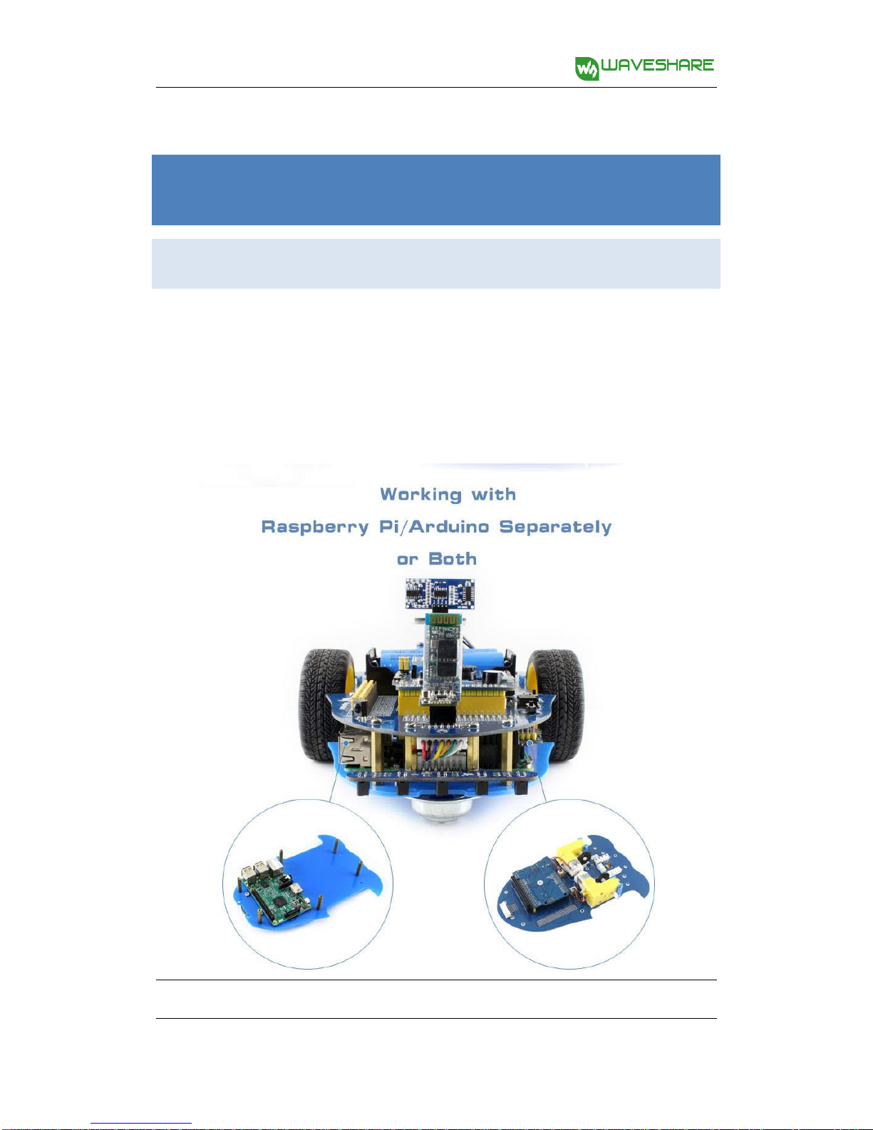
AlphaBot is a robotic development platform compatible with Raspberry Pi and
Arduino. It consists of the AlphaBot mainboard, the mobile chassis, and everything required to get it moving.
Just connecting a controller board, Raspberry Pi or Arduino, and combined with our
open source example code, now it's all ready to start your robotic exploration: line
tracking, obstacle avoidance, video monitoring, WiFi/Bluetooth/ZigBee/Infrared remote control, etc.
AlphaBot can perceive its environment and perform relative response. It involves the following technologies:
Tracking line, obstacle avoidance, mobile phone/PC video monitoring,
WIFI/Bluetooth/ZigBee/infared remote control and the likes.
Notes: This document is not for any specific product kits. Some of them may not
have the component(s) described in the sections below. For more information
about the product kit, please refer to the product page in Waveshare website. Features
Raspberry Pi/Arduino interfaces, works with either one separately, or both 6
Downloaded from www.Manualslib.com manuals search engine AlphaBot User Manual share awesome hardware
Arduino extend header, supports Arduino shields
Modular design, plug-and-play modules like line tracking, obstacle avoidance,
speed measuring, etc. eliminating the trouble of connecting mess wires.
L298P motor driver with diode protection circuit, more safety
LM2596 voltage regular, provides stable 5V power to the Raspberry Pi/Arduino
TLC1543 AD acquisition chip, allows the Pi to use analog sensors Audience
A lot of MCU enthusiasts may have a dream to design their smart robot. However, it
is not easy when they get down to do it. Someone feel difficult maybe because they
do not fully understand the smart robott or they do not know how to start. With
the application kit provided by Waveshare, you can quickly study the smart robot,
including the structural framework, the basic principle and the external modules.
In this document, we will take the example of Waveshare AlphaBot smart robot to
present the working principle and the production process of the smart robot.
Relative example programs are also provided, including tracking line, obstacle
avoidance, Bluetooth remote control and wifi control. This document describes the
smart robot development with the example programs. It is easy to understand,
covering the knowledge of the structural framework from the min. system to the
main control design of the robot, and the function design from the straight line
movement to the multifunction implementation. We sincerely hope that the MCU
hobbyists can have a thorough understand of the smart robot. Due to the limited
knowledge and ability of the author, there is still much room for improvement in 7
Downloaded from www.Manualslib.com manuals search engine AlphaBot User Manual share awesome hardware this paper.
If you have any question, please don’t hesitate to visit Waveshare site
http://www.waveshare.com and leave your message. 8
Downloaded from www.Manualslib.com manuals search engine AlphaBot User Manual share awesome hardware On-board resource
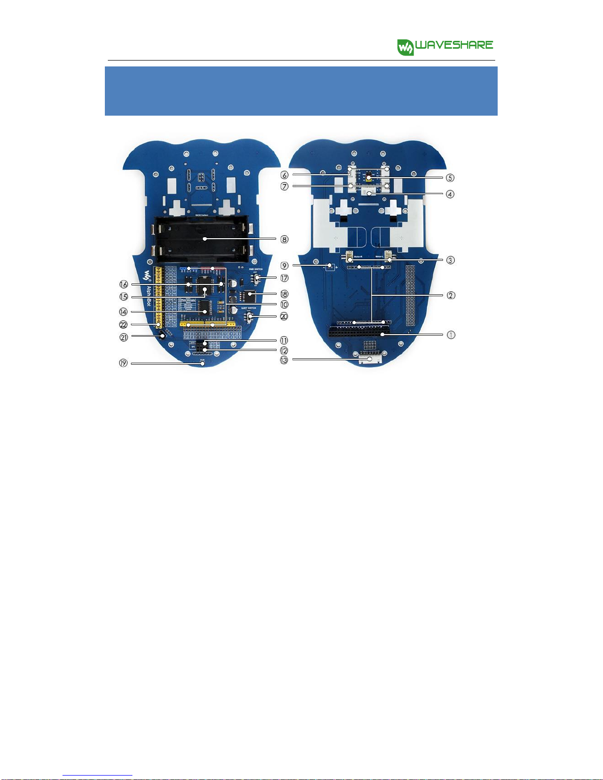
1. Raspberry Pi interface: for connecting Raspberry Pi
2. Arduino interface: for connecting Arduino 3. Motor interface
4. Ultrasonic module interface
5. Servo module interface
6. Obstacle avoidance module interface
7. Speed measuring interface
8. Battery holder: supports 18650 batteries
9. Reserved power input (not soldered): for connecting other external power supply
10. Arduino expansion header: for connecting Arduino shields
11. UART interface: for connecting Bluetooth module, to control the robot remotely via Bluetooth
12. SPI interface: for connecting NRF24L01 wirmoduleeless
13. Line tracking module interface
14. TLC1543: 10-bit AD acquisition chip, allows the Pi to use analog sensors
15. L298P: dual H bridge motor driver chip, up to 2A current 16. Anti-reverse diode 17. Power switch
18. LM2596: 5V regulator 19. Power indicator
20. UART switch: turn on to enable serial communication between Raspberry Pi and Arduino
21. IR receiver: control the robot remotely via infrared 9
Downloaded from www.Manualslib.com manuals search engine AlphaBot User Manual share awesome hardware
22. Raspberry Pi/Arduino selection: select the Raspberry Pi or Arduino to control the robot peripherals Module functions Main control module
The main control module is the key part of the smart robot. AlphaBot provides
Arduino and Raspberry Pi interfaces. Configuration can be one of two options, or
both of them work together. By taking fully use of the hardware and software of
both boards, the smart robot can be applied to much more application scenarios.
☺Working with Arduino or raspbeery Pi can be selected by jumpers. 10
Downloaded from www.Manualslib.com manuals search engine AlphaBot User Manual share awesome hardware Motor driver module
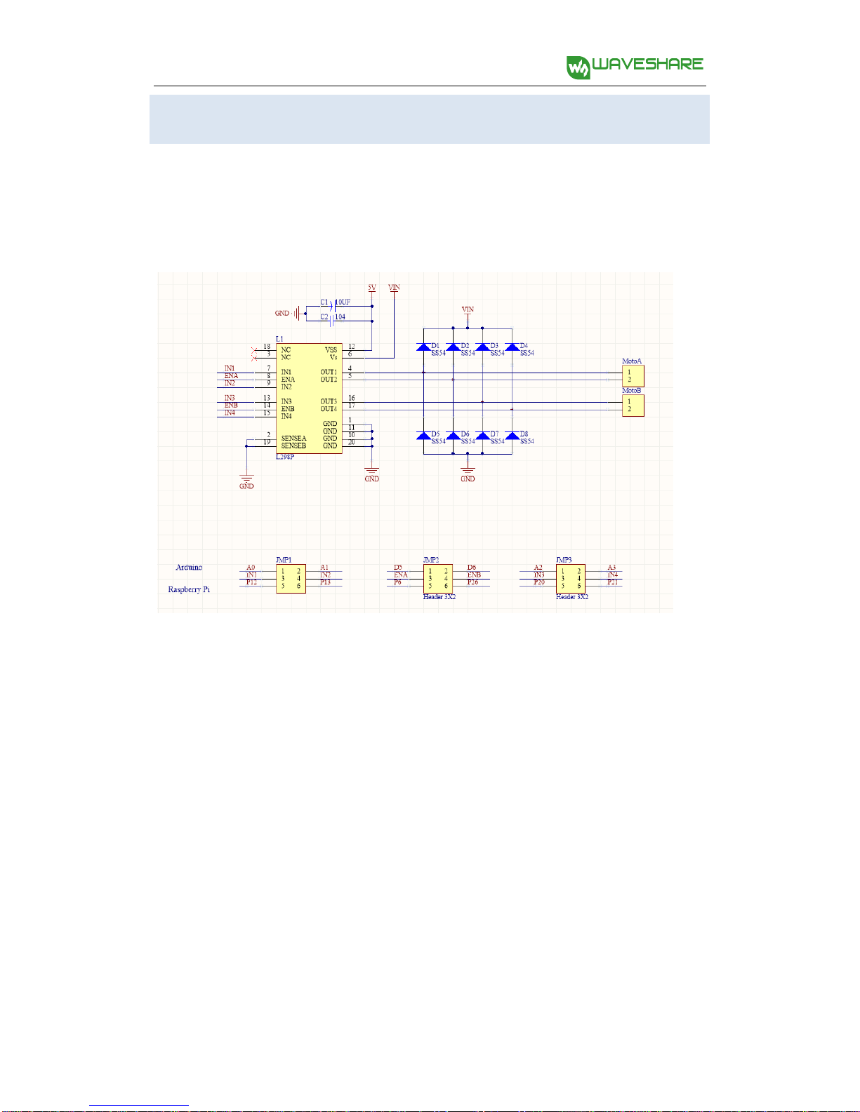
Moter driver module is one of the most important parts of the smart robot.
AlphaBot use the L298P driver chip from ST, which is a high voltage, big current motor driver chip. 11
Downloaded from www.Manualslib.com manuals search engine AlphaBot User Manual share awesome hardware
Interface definition of driver module:
Interfaces Raspberry Pi Arudino IN1 P12 A0 IN2 P13 A1 ENA P6 D5 IN3 P20 A2 IN4 P21 A3 ENB P26 D6
IN1 and IN2 are connected to the left motor, while IN3 and IN4 are connected to the right motor.
ENA and ENB are output enable pins, active high enable. When they are driven to
High level, the PWM pulse will be outputted from IN1, IN2, IN3 and IN4, so as to
control the speed of the motor robot. Control theory: IN1 IN2 IN3 IN4 Descriptions 1 0 0 1
When the motors rotate forwards, the robot goes straight 0 1 1 0
When the motors rotate backwards, the robot draws back 0 0 0 1
When the left motor stops and right motor rotates forwards, the robot turns left 1 0 0 0
When the right motor stops and left motor rotates forwards, the robot turns right 0 0 0 0
When the motors stop, the robot stops 12
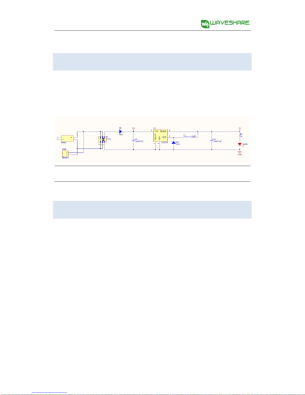
Downloaded from www.Manualslib.com manuals search engine AlphaBot User Manual share awesome hardware Power supply
The smart robot employs two series 18650 batteries for power supply with input
voltage of 7.4V. The input voltage will be deal with the LM2596 regulator, and send
out to Arduino, Raspberry Pi and sensors.
! For using external power supply, the input voltage should not beyond 12V. AD sampling chip
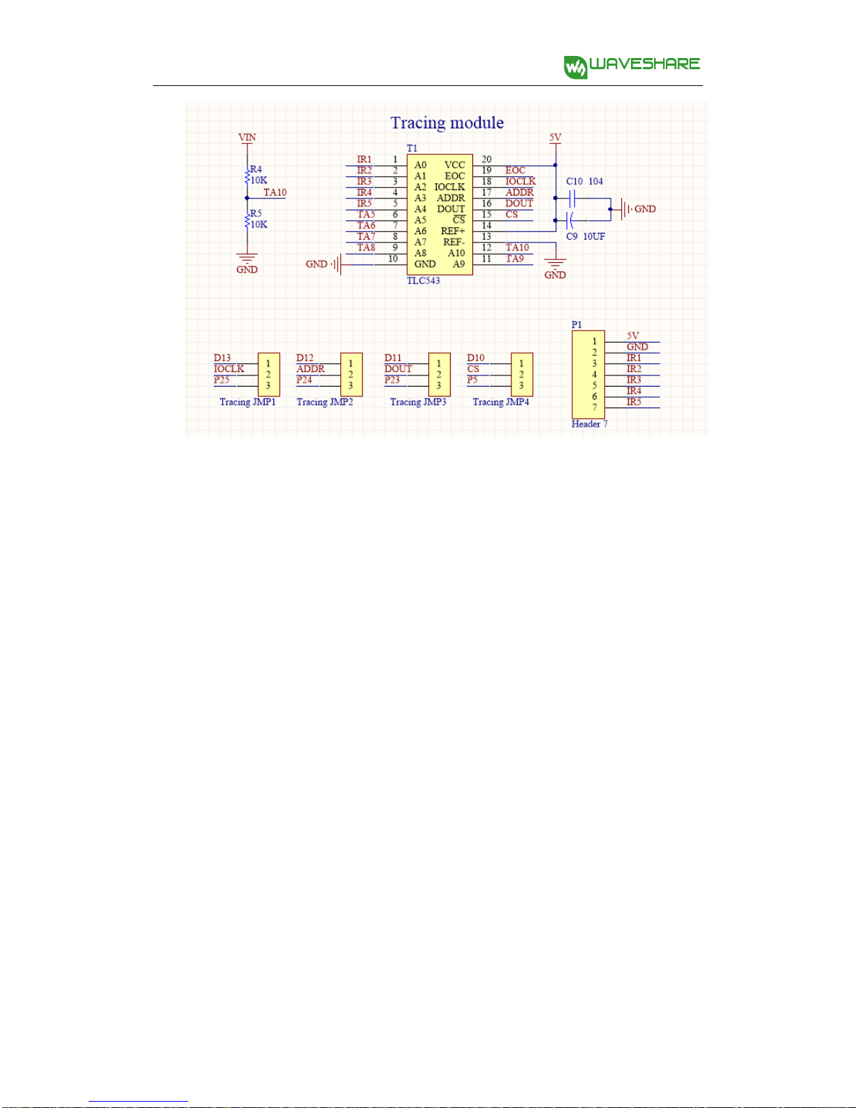
Since the GPIO of raspberry Pi do not support AD function, AlphaBot smart robot
has an on-board 10-bit of 11 channel AD conversion chip for tracking line application.。 13
Downloaded from www.Manualslib.com manuals search engine AlphaBot User Manual share awesome hardware 14
Downloaded from www.Manualslib.com manuals search engine AlphaBot User Manual share awesome hardware
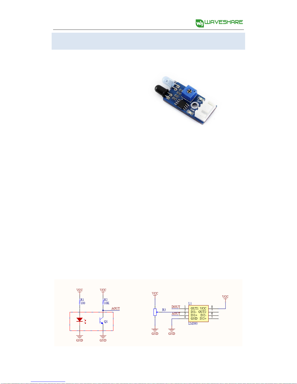
Obstacle avoidance module Obstacle avoidance module consists of an infrared transceiver and a comparator.
The infrared transmitter has an infrared LED array as a luminophor. When there is an obstacle (reflector) on the
detection direction, the Infrared light will be reflected, and received by the infrared
receiver, which is a semiconductor with a PN junction made of a special material as
its core part. As the intensity of the infrared light enhances, more current can be
generated and the analog signal increases. LM393 comparator receives and
handles the analog signal, and then outputs the relative digital signal. At this point,
the green LED will light up. The logical level of the DOUT can tell you whether there
is obstacle in front of the sensor, and the output voltage of AOUT can tell you the
distance from the obstacle if there is. The detection distance can be adjusted via the potentiometer knob. 15
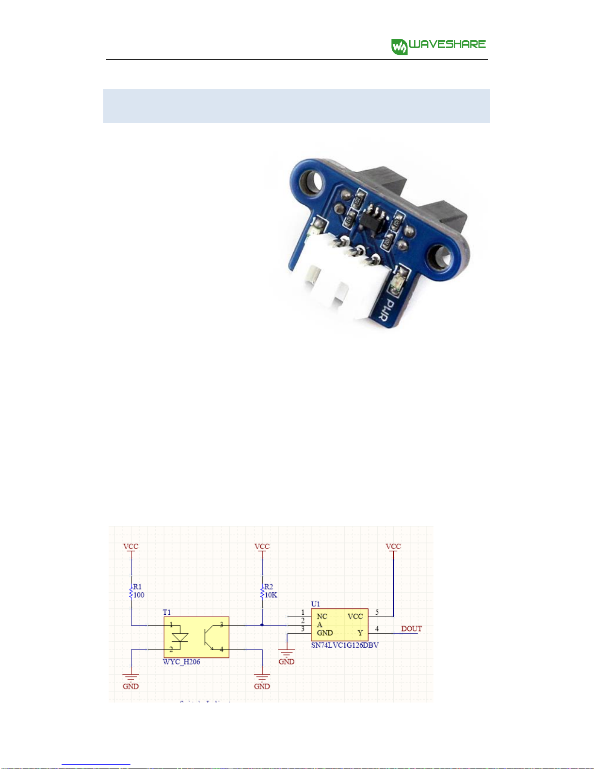
Downloaded from www.Manualslib.com manuals search engine AlphaBot User Manual share awesome hardware Speed testing module The speed testing module contains a coded disc and a
WYC-H206 photoelectric sensor. WYC-H206 photoelectric sensor
has an infrared transmitter and
an infrared receiver. When the
infrared receiver is obscured,
unable to receive infrared light,
the sensor will output a high level voltage. The high level voltage passes the
inverting schmitt trigger and becomes a low level voltage. At this point, the relative
indicator lights up. When the coded disc runs, DOUT will output a series of high
level pulses and low level pulses. By checking the number of the pluses in a cycle
time, you can get the speed of the smart robot. Here, we use the schmitt trigger
because it has a stable output signal, a clear waveform without any jitter. 16
Downloaded from www.Manualslib.com manuals search engine AlphaBot User Manual share awesome hardware
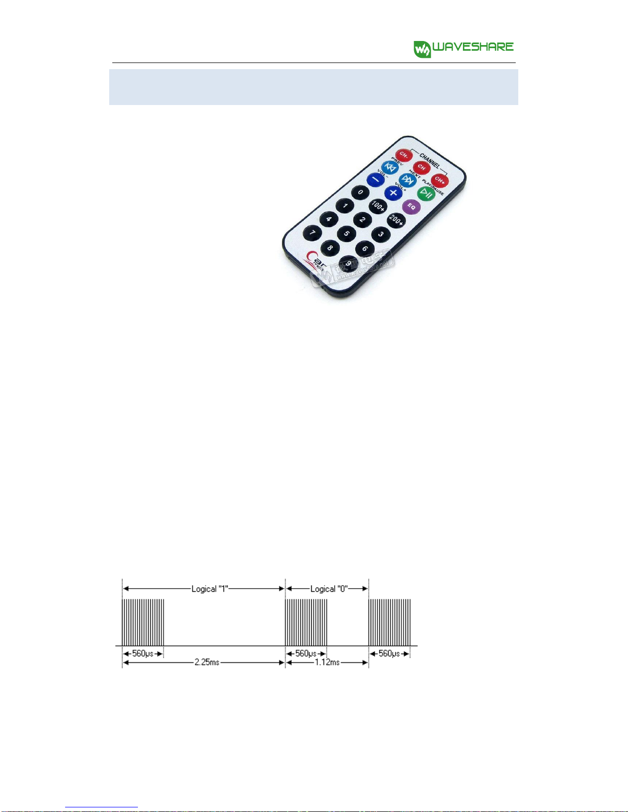
Infrared remote control The smart robot applies LFN0038K receiver to receive infrared signal. The infrared remote controller provided with the application kit, complies with the standard NEC encoding
protocol. When the infrared receiver receives the infrared signal, it will output the
relative pulses to the main control chip. Then, the main control part decode the
signal to the key code, so as to control the corresponding motor.
Infrared NEC protocol encoding is a kind of PWM serial code, in which the binary
logical“0” is in the cycle of 1.125ms with the pulse width 0.565ms and the interval
0.56ms, and the binary logical“1” is in the cycle of 2.25ms with the pulse width
0.565ms and the interval 1.685ms. 17
Downloaded from www.Manualslib.com manuals search engine AlphaBot User Manual share awesome hardware
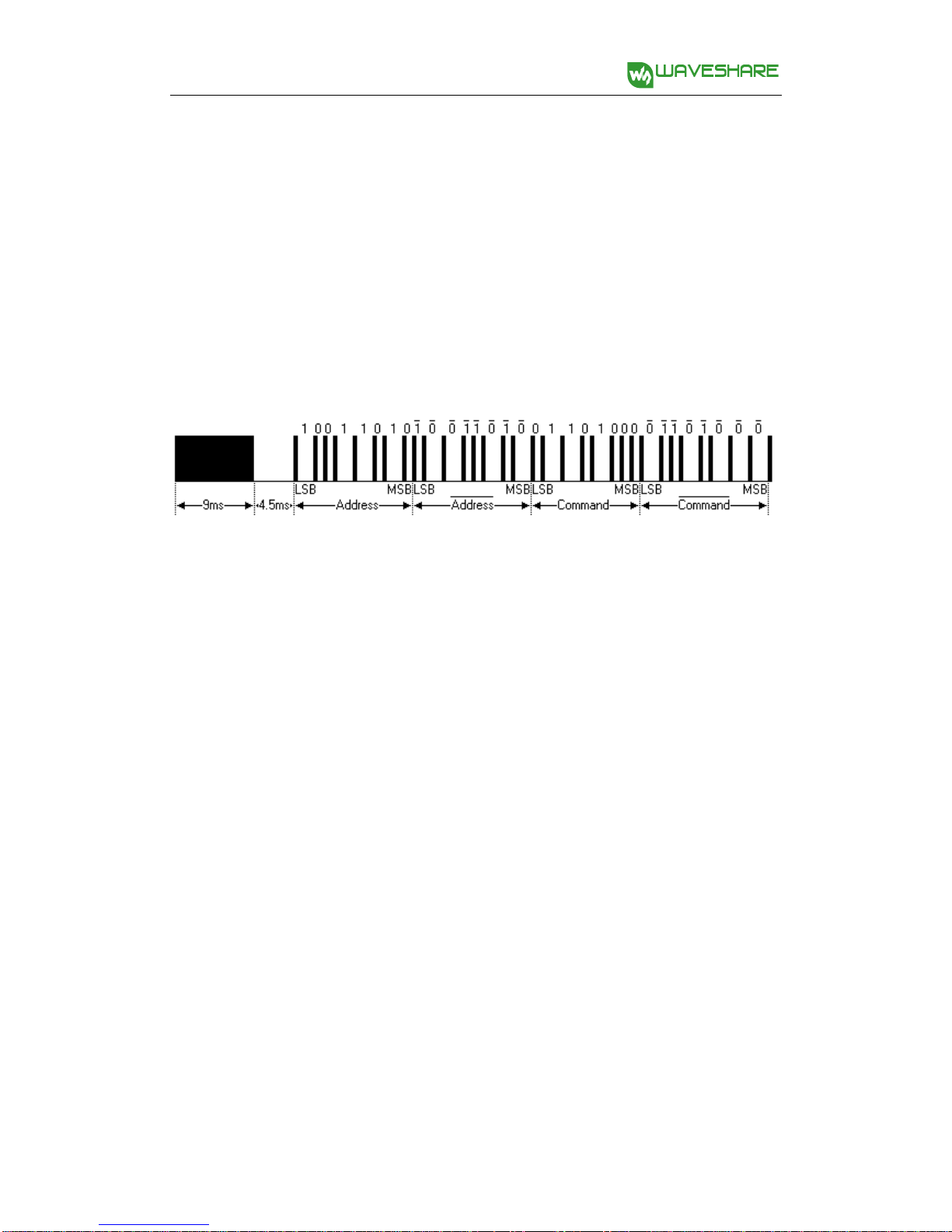
Infrared control protocol:
The 32-bit binary code made up of logical “0” and logical“1” should be
secondary modulated with a 38kHz robotrier frequency, in order to enhance the
transmitting efficiency and reduce the power consumption. The secondary
modulated code will be transmitted in the form of infrared light by a infrared
transmitter, as the figure shows below.
| Boot code | User ID | Radix-minus-one complement of user ID | Op code | Radix-minus-one complement of op code|
Firstly, a 9ms high level pulse is transmitted, and a 4.5ms low level pulse is followed.
Later coming are a 8bit address code (LSB first) and its radix-minus-one
complement (for checking). The last are a 8bit command code (LSB first) and its radix-minus-one complement.
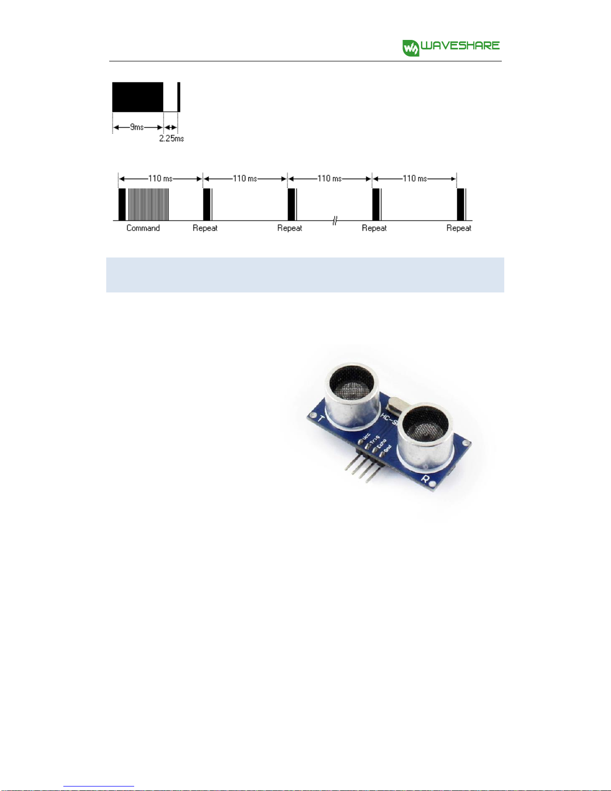
Each command will only be transmitted once, even you keep pressing the key on
the controller. But it will send out a duplication code every 110mS, until you release
the key on the controller. The format of the duplication code is a 9mS of AGC pulse,
a 2.25mS of interval and a 560uS of pulse. 18
Downloaded from www.Manualslib.com manuals search engine AlphaBot User Manual share awesome hardware
Ultrasonic distance measurement module
The ultrasonic distance measurement module has 4 pins, they are VCC, GND, TRIG (transmitting pin) and ECHO (receive pin). Control theory:
Here is the principle of ultrasonic
distance measurement. When the
ultrasonic wave meets a object, it will be reflected back and received by the receiver.
You can get the distance of the object from the sensor by measuring the interval
from transmitting signal to receiving the echo. 19
Downloaded from www.Manualslib.com manuals search engine AlphaBot User Manual share awesome hardware
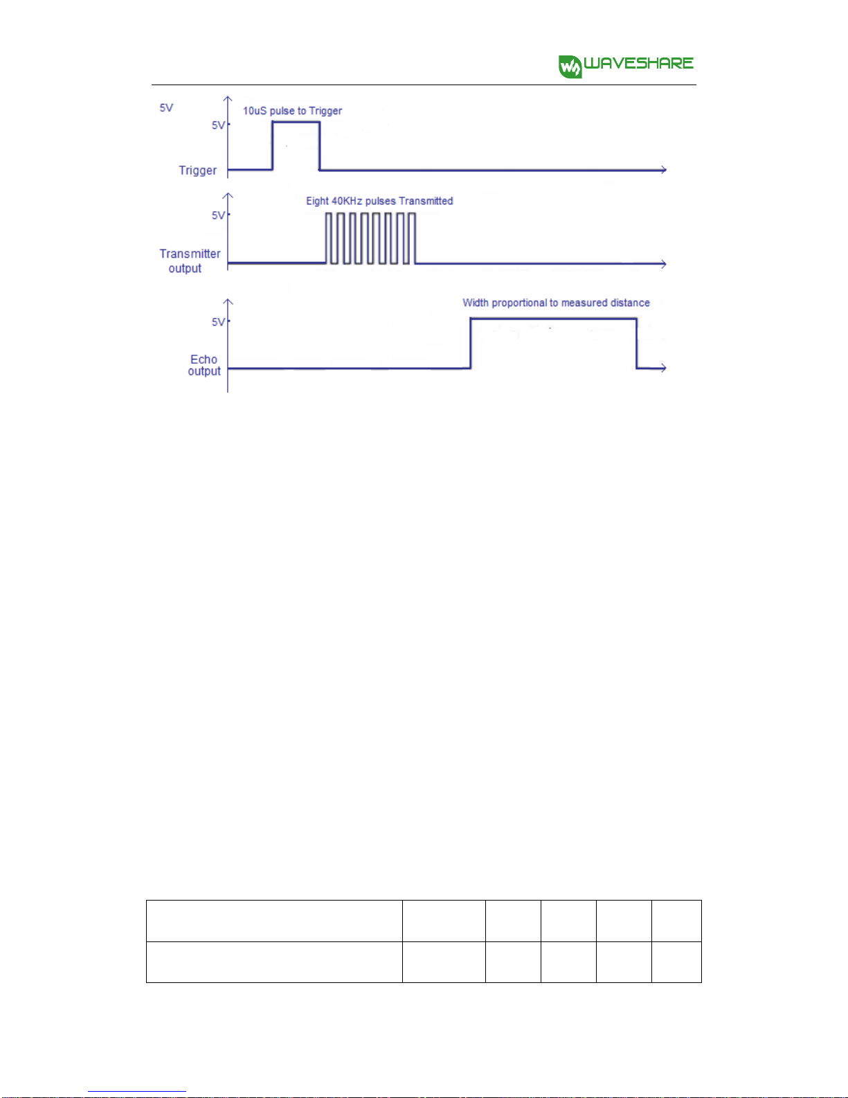
The timing diagram above shows the control principle of ultrasonic distance
measurement. When the module is working, it sends out a high level signal at least
for 10us to control the pin TRIG to trigger distance measurement. Then, the module
transmits 8 serial of 40kHz square wave automatically, to check whether there is
echo signal. If there is, the module outputs a high level voltage from the pin ECHO.
The time duration of the high level voltage is the time of ultrasonic from being
transmitted to reflected. According to the sound transmitting speed and time, we
can get that:measured distance=(measured time*sound speed)/2. The sound speed is 340m/s in here.
Technical Parameters: Parameters Remark Min Typ Max Units Operating voltage 3.0 5.5 V 20
Downloaded from www.Manualslib.com manuals search engine
Tài liệu liên quan:
-
Bài giảng Sorting – Giải thuật sắp xếp môn Cấu trúc dữ liệu và giải thuật | Đại học Bách Khoa Hà Nội
17 9 -
Đề thi cuối kỳ 1 môn Cấu trúc dữ liệu và giải thuật | Đại học Bách Khoa Hà Nội
19 10 -
Bài tập Cấu trúc dữ liệu | Đại học Bách Khoa Hà Nội
20 10 -

Chương 1: Tổng quan cấu trúc dữ liệu và giải thuật
35 18 -

Giáo trình môn Cấu trúc dữ liệu và giải thuật | Đại học Bách Khoa Hà Nội
43 22