Báo cáo thí nghiệm môn Xử lý tín hiệu số | Trường Đại học Bách Khoa Hà Nội
Locate, on the digital signal processor circuit board, all the common terminals. With the power OFF and using an ohmmeter, verify if the common terminals are connected together. Are all the common terminals connected together? Tài liệu được sưu tầm gồm 98 trang, giúp các bạn nắm vững kiến thức, rèn luyện kỹ năng và đạt được kết quả tốt trong học tập. Mời các bạn đón xem!
Môn: Xử lý tín hiệu số hust 33 tài liệu
Trường: Đại học Bách Khoa Hà Nội 5.6 K tài liệu
Tác giả:


Preview text:
ĐẠI HỌC BÁCH KHOA HÀ NỘI
TRƯỜNG ĐIỆN - ĐIỆN TỬ
TRUNG TÂM ĐÀO TẠO THỰC HÀNH ĐIỆN – ĐIỆN TỬ
TÀI LIỆU BÁO CÁO KẾT QUẢ THÍ NGHIỆM
XỬ LÝ TÍN HIỆU SỐ – ET4020 Họ và tên Nguyễn Ngọc Dương MSSV 20192794 Lớp - khóa Điện tử 03 – K64
Mã lớp thí nghiệm 729342
Tên lớp thí nghiệm 729342 Hà Nội, 2022 MỤ ỤC L C
BÀI 1: UNIT 1 - DSP TRAINER FAMILIARIZATION..........................................................3
1.1. EX1: DSP Trainer Familiarization...................................................................................................................3
1.2. EX2: Overview of the DSP Circuit Board........................................................................................................3
1.2.1. Discussion: Overview of the DSP Circuit Board.............................................................................................3
1.2.2. Procedure: Overview of the DSP Circuit Board.............................................................................................3
1.2.3. Review Questions..........................................................................................................................................6
1.3. EX3: Integrated Development Environment (IDE) and Project Structure........................................................7
1.3.1. Integrated Development Environment (IDE) and Project Structure: Discussion...........................................7
1.3.2. Procedure: Integrated Development Environment (IDE) and Project Structure............................................7
Editing Memory and Registers.....................................................................................................................12
1.3.3. Review Questions........................................................................................................................................13
1.4. Unit Test.................................................................................................................................................... 14
BÀI 2: UNIT 2 - ARCHITECTURE.........................................................................................17
2.1. Architecture: Fundamentals........................................................................................................................17
2.2. EX01: Processor Arithmetic.........................................................................................................................17
2.2.1. Discussion: Processor Arithmetic................................................................................................................17
2.2.2. Procedure: Processor Arithmetic.................................................................................................................17
Converting a Signed Fractional Number to Q14-Format.............................................................................17
Converting a Binary Number to a Decimal Value.........................................................................................18
Comparing the Multiplication of Integers to the Multiplication of Floats on a Fixed-point DSP..................22
2.2.3. Review Questions........................................................................................................................................23
2.3. EX02: Data Computation Unit.....................................................................................................................24
2.3.1. Discussion: Data Computation Unit.............................................................................................................24
2.3.2. Procedure: Data Computation Unit.............................................................................................................24
Set Up of the DSP Board..............................................................................................................................24
Overflow, Saturation Mode and Carry Bit....................................................................................................27
2.3.3. Review Questions........................................................................................................................................30
2.4. EX03: Memory............................................................................................................................................31
2.4.1. Discussion: Memory....................................................................................................................................31
2.4.2. Procedure: Memory....................................................................................................................................31
Set Up and Connections of the DSP Board..................................................................................................31
Testing the Program.....................................................................................................................................32
2.4.3. Review Questions........................................................................................................................................37
2.5. EX04: Addressing........................................................................................................................................38
2.5.1. Discussion: Addressing................................................................................................................................38
2.5.2. Procedure: Addressing................................................................................................................................38
Set Up and Connections of the DSP Board..................................................................................................39
2.5.3. Review Questions........................................................................................................................................44
2.6. Unit Test................................................................................................................................................... 45
BÀI 3: I/O AND PERIPHERALS............................................................................................48
3.1. I/O and Peripherals: Fundamentals.............................................................................................................48
3.2. EX01: An Application Using I/Os and Peripherals........................................................................................48
3.2.1. Discussion: An Application Using I/Os and Peripherals...............................................................................48
3.2.2. Procedure: An Application Using I/Os and Peripherals...............................................................................48
Set Up and Connections of the DSP Board.....................................................................................................48
Peripheral Registers........................................................................................................................................49
3.2.3. Review Questions........................................................................................................................................50
3.3. Unit Test.................................................................................................................................................... 51
BÀI 4: DSP REAL-TIME PROCESSING...............................................................................54
4.1. DSP Real-time Processing: Fundamentals....................................................................................................54
4.2. EX01: Sampling and Analog-to-Digital/Digital-to-Analog Conversion...........................................................54
4.2.1. Discussion: Sampling and Analog-to-Digital/Digital-to-Analog Conversion.................................................54
4.2.2. Procedure: Sampling and Analog-to-Digital/Digital-to-Analog Conversion.................................................54
The Sampling Application Used in This Exercise.............................................................................................54
4.2.3. Review Questions........................................................................................................................................63
4.3. EX02: The FFT and Optimizing DSP Applications..........................................................................................64
4.3.1. Discussion: The FFT and Optimizing DSP Applications................................................................................64
4.3.2. Procedure: The FFT and Optimizing DSP Applications.................................................................................65
The FFT Application Used in the Exercise.......................................................................................................65
4.3.3. Review Questions........................................................................................................................................76
4.4. Unit Test.................................................................................................................................................... 78
BÀI 5:..........................................................................................................................................79
5.1. Signal Processing Applications: Fundamentals............................................................................................79
5.2. EX01: Applications - FIR and IIR Filters........................................................................................................79
5.2.1. Discussion: Applications - FIR and IIR Filters...............................................................................................79
5.2.2. Procedure: Applications - FIR and IIR Filters...............................................................................................79
5.2.3. Review Questions........................................................................................................................................79
5.3. Unit Test.................................................................................................................................................... 79 GIỚ ỆI THI U
Tài liệu này ghi nhận các kết quả thí nghiệm của sinh viên dựa trên quá trình làm
việc thực tế với bo mạch và các thiết bị thí nghiệm.
BÀI 1: UNIT 1 - DSP Trainer Familiarization
1.1. EX1: DSP Trainer Familiarization
o DSP Trainer Familiarization: Introduction
o Types of Microprocessors o Peculiarities of DSPs o Program Execution
1.2. EX2: Overview of the DSP Circuit Board
1.2.1. Discussion: Overview of the DSP Circuit Board
o Discussion o The Accessories Section o The DSP and its Peripherals Section
1.2.2. Procedure: Overview of the DSP Circuit Board
In this section, you will begin to familiarize yourself with some of the components
and circuit blocks found on the digital signal processor circuit board.
1. Locate, on the digital signal processor circuit board, all the common terminals. With
the power OFF and using an ohmmeter, verify if the common terminals are
connected together. Are all the common terminals connected together?:
a................................................................................................................yes
b................................................................................................................no Choose Answer: a
2. Turn the power supply ON to power the circuit board.
3. Using a dc voltmeter, measure the voltage range at the output of the dc source circuit
block. To do so, vary the potentiometer of the dc source from its smallest to its
largest values. What is the minimum voltage and maximum voiltage: Vmin(V)=-0.8 Vmax(V)=0.9
4. Connect a microphone to the input of the microphone pre-amplifier and connect the
output of the pre-amplifier to the input of the audio amplifier. Note: “You can also
use earphones if you are in an area where an audio output from the speaker is not desirable.
5. While talking into the microphone, familiarize yourself with the use of the
potentiometers of the microphone pre-amplifier and of the audio amplifier blocks.
6. Remove all the connections (leads) present on the circuit board
Familiarization with the Circuit Board Using a DSP Program
In this section, you will familiarize yourself with the development environment and
you will load and run a program on the DSP.
7. Connect the DSP board to your computer using USB port number 2 on the board
and a standard USB port on your computer. Make sure that the circuit board power
source is turned ON and that the Code Composer software is installed as explained
in Appendix C. Launch Code Composer on your computer.
8. Make exercise_1_1 the active project simply by clicking on that project in the
Project Explorer window. Launch the Debug mode by clicking the icon to load
the program into the DSP. Next, press the icon in the menu where the debug
icon was in order to run the program. At this point, you should see the following
information on the LCD of the DSP circuit board: LabVolt 91031 Ex1-1 Echo Generator.
9. Perform the connections shown.
10.Adjust the DIP switch of the I/O interface so that every bit is in the 0 position. Press the
interrupt button so that the LCD displays an Echo Delay 0ms.
11.Using the microphone, input a signal (your voice) into the DSP. Adjust the GAIN
potentiometers of the pre-amplifier and of the audio amplifier to obtain a good
quality of sound at the output. Experiment with the potentiometers. Note that a
series of black rectangles light up on the last line of the LCD as you talk into the
microphone. The length of that line corresponds to the magnitude of the input
signal from the microphone pre-amplifier. The program you downloaded into the
DSP takes the input from the CODEC (which you connected to the microphone
pre-amplifier), displays its amplitude on the LCD, and processes the signal which
is then sent to the output of the CODEC (connected to the speaker/headphones).
12.Adjust the DIP switch such that the 8-bit number sent to the DSP corresponds to
15 (or 0000 1111b, that is, 0000 111 in binary). Set the switches
corresponding to a one (1) to the I position. Press the interrupt button so that
the LCD displays an Echo Delay 15ms. Notice the effect of the signal processing on the sound of your voice.
13.Repeat the last step with the following DIP switch values: 031 (0001 1111) 063 (0011 1111) 127 (0111 1111) 255 (1111 1111)
The echo effect should be quite obvious. The echo delay corresponds to the time
(in milliseconds) between consecutive echoes.
What is the minimal time required for your brain to perceive distinct repetitions?
a................................................................................................................Ty pically 5 to 15 ms
b................................................................................................................Ty pically 20 to 80 ms
c................................................................................................................Ty pically 100 to 160 ms
d................................................................................................................Ty pically 180 to 300 ms Choose Answer: b
14.Click on the icon (next to the Run icon) to terminate the execution of the program. Using a second application
In this section, you will experiment with a different program using the same connections.
15.Make exercise_1_1b the active project simply by clicking on that project in the
Project Explorer window. Launch the Debug mode by clicking the icon to load
the program into the DSP. Next, press the to run the program. At this point, you
should see the following information on the LCD of the DSP circuit board: LabVolt
91031 Ex1-1b Echo/Flanger Generator.
16.Experiment with this application. Press the and interrupt buttons and modify the
value of the DIP switch. Speak in the microphone or use a sound signal. What is the function of pressing the
interrupt button in this application?
a................................................................................................................To select Voice mode
b................................................................................................................To select Echo mode
c................................................................................................................To select Flanger mode
d................................................................................................................All of the above Choose Answer: d
What is the function of pressing the
interrupt button in this application? a. To change the mode
b................................................................................................................To
update the variable (value read from the DIP switch)
c................................................................................................................To reset the DIP switch
d................................................................................................................All of the above Choose Answer: b
17.Click on the icon to terminate the execution of the program. Return to the
projects tab and quit Code Composer. Turn OFF the power supply and remove the
connections (leads) you made on the circuit board.
1.2.3. Review Questions
1. Before the DSP circuit board can be used, a few steps must first be taken. Which steps
must be completed before using the board?
a. Make certain that the DIP switches of the I/O interface are all in the OFF position
b. Make certain that a USB connection between the board and the computer is present
c. Make certain that the power source of the board is turned ON d. Both b. and c Choose Answer: d
2. What is the range of the dc voltage source of the DSP board? a. -3.3 V to 3.6 V b. -3.5 v to 3.5 V c. -0.8 V to 0.9 V d. -4.4 V to 7.3 V Choose Answer: c
3. What does the TMS320C5535 chip found on the DSP circuit board use to set the
frequency of its master clock?
a. The DSP uses its 100 MHz internal oscillator.
b. The DSP uses a 32.768 kHz external oscillator and a phase-locked loop.
c. The DSP uses the 33.3 MHz oscillator of the CODEC.
d. The DSP uses the clock of the computer through the USB connection. Choose Answer: b d
4. Which of the following components is usually found in a CODEC? a. An anti-aliasing filter
b. An analog-to-digital converter
c. A digital-to-analog converter d. All of the above Choose Answer: d
5. Increasing the echo delay has which effect on the signal at the output of the DSP?
a. It increases the echo effect.
b. It increases the time between consecutive echoes.
c. The sound seems more remote. d. All of the above Choose Answer: d
1.3. EX3: Integrated Development Environment (IDE) and Project Structure
1.3.1. Integrated Development Environment (IDE) and Project Structure: Discussion
o The Code Composer Studio Software o The
Code Development Perspective o Project Structure
o C Code o Assembly Code o Configuration
File o The Debug Perspective o
Breakpoints o Registers, Expressions, and Variables Windows
1.3.2. Procedure: Integrated Development Environment (IDE) and Project Structure
1. Connect the output of the DC source to the analog input of the CODEC and the
analog output of the CODEC to the audio amplifier as shown. Also, connect one
channel of your oscilloscope to the analog output of the CODEC.
2. Connect the DSP board to your computer using USB port number 2 on the board
and a standard USB port on your computer. Make sure that the circuit board power
source is turned ON and that the Code Composer software is installed as explained in Appendix C.
Launch Code Composer on your computer.
3. Make exercise_1_2 the active project simply by clicking on that project in the Project Explorer window.
4. Launch the Debug mode by clicking the
icon to load the program into the DSP. Do not run the program yet.
5. Where is the memory address identified at which the main function starts?
a................................................................................................................In the Project Explorer window
b................................................................................................................In
the Debug window at the end of the main() function string
c................................................................................................................In
the Disassembly window at the start of the debug session
d................................................................................................................Bot h b and c Choose Answer: d
6. Go to the Registers tab and look for the Program Counter (PC) register. This register
is in the Core Registers list. Is the value of the PC register the same as the main function starting address?
a................................................................................................................Ye s
b................................................................................................................No Choose Answer: a
Press the assembly step into button to go to the next assembly instruction. What
is the value of the PC register now?
a. The next sequential address in the program
b................................................................................................................Th
e main function starting address
c................................................................................................................Th e function ending address
d................................................................................................................No ne of the above Choose Answer: a
What does this number correspond to?
a. The address where the main function started
b................................................................................................................Th
e address of the current assembly instruction
c................................................................................................................Th
e total number of program lines
d................................................................................................................Th
e address of the last assembly instruction Choose Answer: b
What is the use of the Program Counter register?
a. To keep track of the total number of instruction addresses in the memory.
b................................................................................................................To
keep track of the total number of programs in the memory.
c................................................................................................................To
keep track of the address of the current instruction in the memory.
d................................................................................................................All of the above Choose Answer: c
7. While keeping an eye on the main.c, Disassembly and Variables tabs, experiment
with the different debugger step arrows to observe what happens with the debugger and the different variables. 8. Press the run button
to run the program on the board. Adjust the GAIN
potentiometer of the audio amplifier to obtain a sound output of the appropriate
volume. At this point, you should see the following information on the LCD of the
DSP circuit board: LabVolt 91031 Ex1-2 - Sin Generator freq = x Hz (where x is a number).
9. It should be quite obvious by the name on the LCD and by playing with the dc source
knob that this application generates a sinusoidal waveform which is heard from the
loudspeaker (or earphones). Adjust the potentiometer of the dc source and observe the result on the signal:
a................................................................................................................Th
e frequency of the signal displayed is modified as the potentiometer is adjusted.
b................................................................................................................Th
e value of the frequency is also modified accordingly on the LCD.
c................................................................................................................As
the frequency changes the audio signal also changes.
d................................................................................................................All of the above Choose Answer: d
10.Use an oscilloscope to observe the signal at the analog output of the CODEC. Does
the amplitude of the signal change as you change the frequency?
a................................................................................................................Ye s
b................................................................................................................No Choose Answer: b
What is the obtainable range of frequency?
a. The frequency can go from about 1 Hz to 500 Hz ± 5%.
b................................................................................................................Th
e frequency can go from about 50 Hz to 50 kHz ± 5%.
c................................................................................................................Th
e frequency can go from about 10 Hz to 5027 Hz ± 5%. Choose Answer: c 11.Click on the
icon to halt the execution of code.
12.A crucial part of debugging is to be able to know the value of a given variable at a
given moment in the process. This can be done in most cases using the Expressions
or Variables tabs. Here is a case where this method is not as convenient:
In the main.c file of Exercise 1-2, a table is declared on line 22 like this: Int16 sintbl[2048];
This means that sintbl is a table containing 2048 elements which are all 16-bit integers.
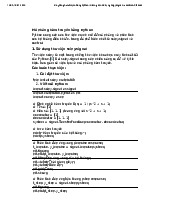
On lines 47 to 51 of the main.c file, a loop calculates a value for each of the
elements of the sintbl variable: // fill sin table for (i=0; i<2048;i++) {
sintbl[i]=sin (i/2048.0 * 2.0 *3.14159265) * 32767; }
Open the Expressions tab and type sintbl in the field to obtain the values of
the sintbl table of integers. It is necessary to expand the display to see an element of
interest. Note the address of the sintbl variable: 0x86
13.Another method is to open a Memory window to visualize the data table. Go to the
View menu of Code Composer and choose Memory Browser to open a new window.
sintbl variable = recall(hex1)
Search for the address of the sintbl variable in the Memory window. Specify that
the looked-after variable is in the DATA part of the memory and that its type is 16-bit signed integer.
The content of the memory can thus be observed in a table such as this:
This is an improvement, but due to the sheer size of the sintbl integer table, a
different method should be used.
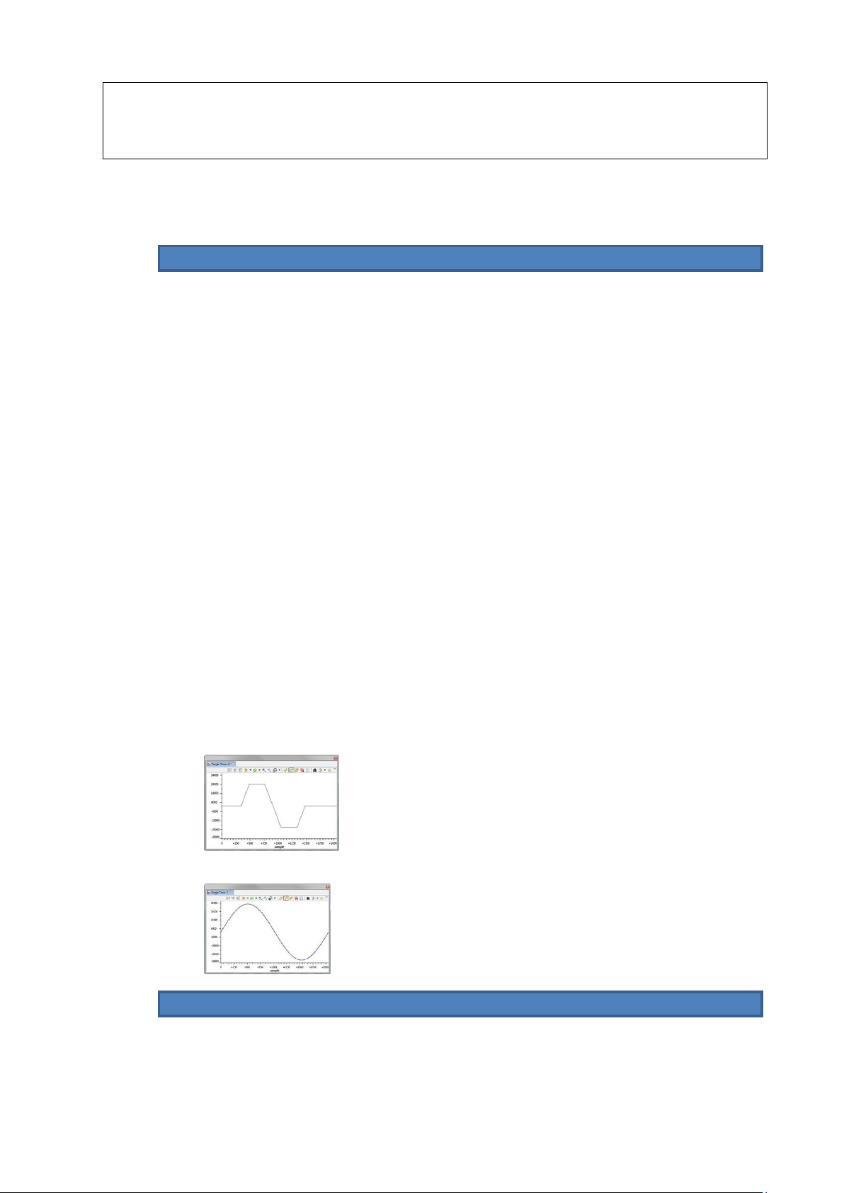
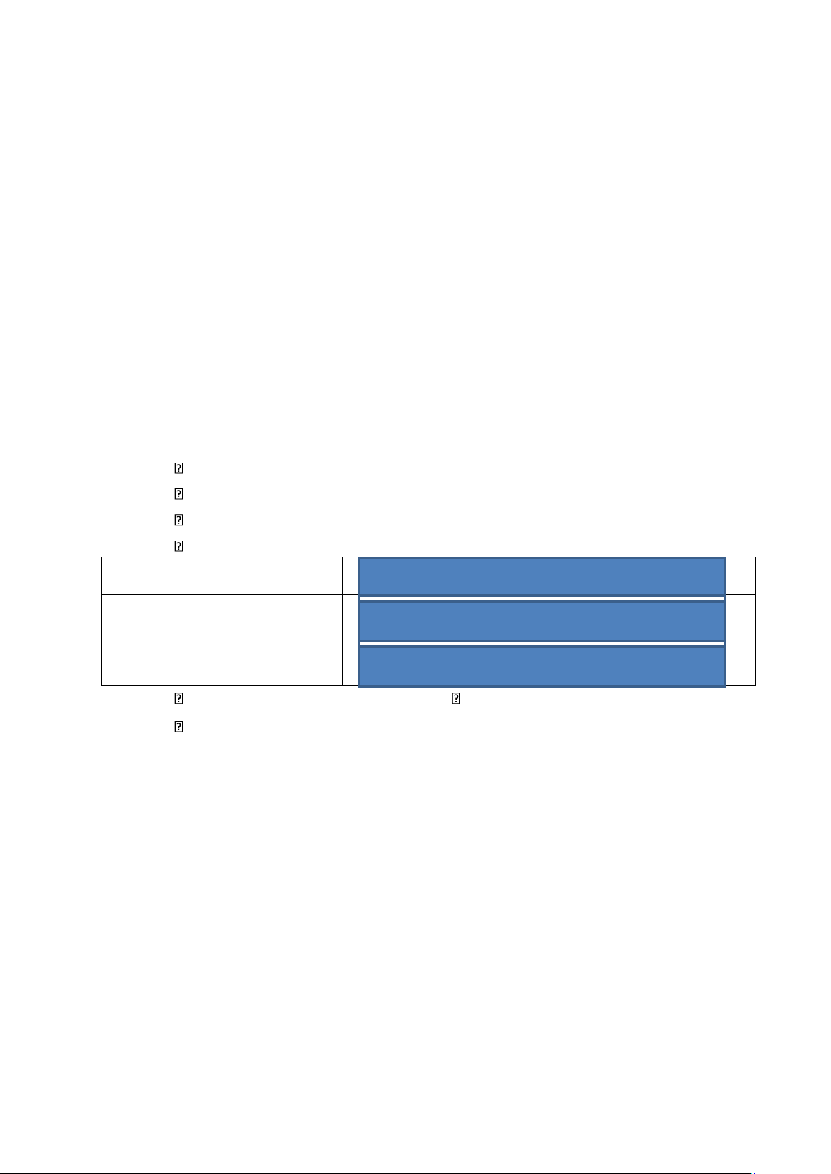
14.Another method to visualize a large array of data is to use the graphics display tool.
15.In the Tools menu, choose Graph, then Single Time. In the dialog box, set the
parameters as shown and click OK. The Start Address is the location in memory
where the table begins. The sintbl variable contains that address.
Which of the following best represents the resulting graph of the contents of the sintbl table?
a................................................................................................................
b................................................................................................................ Choose Answer: a
16.The use of breakpoints is very important to any debug process. With the debug
process halted, insert a breakpoint in the main function below the comment
identified as “ //Breakpoint #01 ” in the code. Do so by double clicking to the left
of the line number below the Breakpoint #01 identifier in the code. In the
expressions tab, keep an eye on the value of the freq variable.
Press the run button to run the program. The execution of the program should
halt pretty quickly at the appropriate line in the main function. Note the value of the freq variable: 2531.25
Adjust the dc source potentiometer in any direction and press the run button
again. The process should run briefly until it halts again at the same line of code.
Observed freq variable = recall(fib1)
Is the current value of the freq variable the same or close to the same as observed in the previous step?
a................................................................................................................Ye s
b................................................................................................................No Choose Answer: a
Press the yellow step into arrow to execute the current line.
What is the value of the freq variable now?
a. The value remained the same
b................................................................................................................Th
e value updated corresponding to the new position of the dc source potentiometer
c................................................................................................................Th e value has dropped to zero
d................................................................................................................No ne of the above Choose Answer: b
17.It is possible to go deeper in the code by placing a breakpoint in the assembly code directly.
The breakpoint which was placed below the “ //Breakpoint #01 ” identifier in the
C code corresponds to a breakpoint automatically placed in the disassembly code at address 0x023059.
Add a breakpoint in the Disassembly window at address 0x023086.
This adds a corresponding breakpoint in the main.c file at which line? 70
Breakpoint line = recall(fib2)
Remove the breakpoint at address 0x023086, then add a breakpoint in the main.c
file at the line you just wrote down.
At which address in the Disassembly window is a breakpoint added?
a................................................................................................................0x 023086
b................................................................................................................0x 023049
c................................................................................................................0x 023059
d................................................................................................................0x 02307C Choose Answer:d
Was the instruction at address 0x023046 the beginning of the corresponding instruction in C? a. Yes
b................................................................................................................No Choose Answer:b Why?
a. Instruction 0x023086 was an intermediate step of the command, not its beginning (0x02307C).
b................................................................................................................Th
e instruction at address 0x023046 was an include statement.
c................................................................................................................Th
e instruction at address 0x023046 was a comment only. Choose Answer:a
Remove all breakpoints inserted so far
Editing Memory and Registers
18.Open the interrupt.c program file. Place a breakpoint after the “ //Breakpoint #02 “
identifier. Observe that the index variable is modified by this line of code. Open
the Expressions tab and add the index variable to the list of variables of interest.
It is possible to edit the value of the index variable from the Expressions tab. Click
on the Value field and change the value of the variable.
19.It is also possible to edit the registers of the DSP. Open the Registers tab and locate
the XAR1 register in the Core Registers. Click on the value field and edit the value
of the register (in hexadecimal).
Remove the breakpoint and run the debugger again by pressing the run button .
The program should be running properly.
20.Halt the program again (
) and edit the PC register in the Registers tab (Core
Registers) to this value: 0x023129.
Run the program again ( ) Does it perform as intended?
a................................................................................................................Ye s
b................................................................................................................No Choose Answer:b
21.Click on the icon to terminate the execution of the program. Return to the
projects tab and quit Code Composer.
22.Turn OFF the power supply and remove the connections (leads) you made on the circuit board.
1.3.3. Review Questions
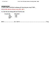
1. Which is the correct syntax for an assembly source statement?
a. mnemonic [operand list] [Label + :] [; + comment]
b. [Label + :] [operand list] mnemonic [; + comment]
c. [Label + :] mnemonic [; + comment] [operand list]
d. [Label + :] mnemonic [operand list] [; + comment] Choose Answer:d
2. What step(s) must you perform to execute a program from within the Code Composer Studio software?
a. Turn the power on to the DSP circuit board and connect it to your computer.
b. Launch Code Composer and start the debug mode for your program.
c. Execute the Run command from the Debug toolbar. d. All of the above Choose Answer:d
3. Which of these features of Code Composer is false? Code Composer Studio allows a developer:
a. to run and halt a program and execute single instructions.
b. to automatically generate C code for any application.
c. to place breakpoints at source statements.
d. to edit, build, debug, and manage DSP projects. Choose Answer:b
4. Which of the following sentences is correct?
a. The breakpoints disappear when a program is executed in debug mode.
b. Breakpoints are not used by serious programmers.
c. The program is automatically halted when an execution line reaches a breakpoint. d. All of the above Choose Answer:c
5. What are the best ways to visualize a large table of data? a. The Expressions tab b. The Graph tool c. The Memory window
d. b. or c., depending on the type of data Choose Answer:d 1.4. Unit Test
1. What characterizes a digital signal processor?
a. Specialized internal structures that make them execute commands rapidly and efficiently b. Fast multiply instructions
c. Reduced set of instructions, making the programming of DSP simpler d. All of the above Choose Answer:d
2. Which of the following is not displayed in one of the columns of the Disassembly
window in Code Composer Studio? a. The CPU register
b. The machine code instruction c. The instruction mnemonic d. The instruction operand(s) Choose Answer:c
3. Which of the following is written in machine code?
a. if(freq > 300) then (freq = freq*2)
b. 0x022F25 ADD #4369 << #3,AC0,AC0 c. 1011 1110 0001 0011 d. OMEGA: MPY #031h. Choose Answer:b
4. Which of the following statements about digital signal processors is not true?
a. They allow for more complex processing of signals than is possible with analog circuitry.
b. They are less common than before in high-tech devices.
c. They provide repeatable performance.
d. Digital processing code can be easily modified, making design updates or changes more flexible. Choose Answer:c
5. What files are generated by Code Composer when a program is compiled and built? a. .obj files b. .asm files c. .out files d. Both a. and c. Choose Answer:b
6. Which of the following circuit blocks can be used to interact with a DSP program? a. interrupts b. Microphone pre-amplifier c. Auxiliary power input d. Audio amplifier Choose Answer:c
7. What is the role of the CODEC? a. It detects code problems.
b. It encodes the data from the DSP into a string of ones.
c. It transforms an input analog signal into a digital one and transforms the
output digital signal into an analog one.
d. It produces machine code for the DSP. Choose Answer:d
8. The output of the dc source is adjusted with:
a. a setting in Code Composer. b. a potentiometer. c. a lever. d. It cannot be adjusted. Choose Answer:d
9. The auxiliary power input is used to:
a. generate power for the DSP board.
b. adjust the level of the input signal of the microphone.
c. receive power from an external source and distribute it to the DSP board. d. All of the aboveabove Choose Answer:a 10.Code in C is:
a. written in a high-level language. b. is device dependent.
c. is device independent or portable. d. Both a. and c. Choose Answer:a
BÀI 2: UNIT 2 - Architecture
2.1. Architecture: Fundamentals
o Architecture: Introduction o The Von
Neumann Architecture o The Harvard
Architecture o The Architecture of the TMS320C5535
2.2. EX01: Processor Arithmetic
2.2.1. Discussion: Processor Arithmetic
o Fixed-Point and Floating-Point DSPs o
Binary and Hexadecimal Numbers Introduction Decimal to Binary Conversion Binary to Decimal Conversion Hexadecimal Numbers Enter decimal number: 338 Binary 101010010 Hexadecimal: 152
Decimal to Hexadecimal Conversion Hexadecimal to Decimal Conversion
Binary to Hexadecimal and Hexadecimal to Binary Conversion o Two’s
Complement Representation (2s-format) o Fractional Numbers – Q-
Format o Fractional Numbers – Floating-Point Format
2.2.2. Procedure: Processor Arithmetic
Converting a Signed Fractional Number to Q14-Format
1. Convert -0.984375, a decimal signed fractional number to a binary Q14-format. To
do so, open the Microsoft® Calculator tool or an equivalent one able to perform
base conversions. A pocket calculator with base conversion features works well too.
2. With your calculator, multiply -0.984375 by 2^14. This scales the fractional
decimal value to an integral decimal value and makes it easy to convert this number
to a binary number (in 2s-format). What is the integral decimal value obtained? -16128
3. Use the decimal to binary conversion tool of your calculator to obtain a one Word
(16 bits) binary value. You might have to specify that you want a Word result by clicking a checkbox.
What is the binary result obtained? 1100 0001 0000 0000
What does it corresponds to in 2sformat? -16128 In Q14-format? -0.984375
binary result obtained = recall(fib2)
4. Verify that the binary number you just obtained is equal to the decimal value
0.984375. Use the Q14-format weights to calculate the decimal value. -0.984375
Converting a Binary Number to a Decimal Value
Convert the following number to a decimal value in the following cases: B093h = 1011 0000 1001 0011b
5. The hexadecimal number represents an unsigned integer. Identify the bit weights
associated to this representation:
a................................................................................................................
b................................................................................................................ Choose Answer:b
Calculate the resulting decimal value and select the correct result. Choose Answer:a
Tài liệu liên quan:
-
Bài Tập Chương 2: Cơ Học - Tính Toán Lực và Gia Tốc môn Xử lý tín hiệu số| Đại học Bách khoa Hà Nội
31 16 -
Lấy Mẫu và Lượng Tử Hóa Tín Hiệu Trên Kit C6713 DSK - Báo Cáo Thí Nghiệm môn Xử lý tín hiệu số| Đại học Bách khoa Hà Nội
32 16 -
Mô phỏng hàm truyền trong Python: Hướng dẫn sử dụng scipy.signal và control môn Xử lý tín hiệu số| Đại học Bách khoa Hà Nội
33 17 -
VXL HK231 DE1 DA Final Exam Solutions and Code Explanations môn Xử lý tín hiệu số| Đại học Bách khoa Hà Nội
34 17 -
A Model for Mobile Content Filtering in Recommendation Systems môn Xử lý tín hiệu số| Đại học Bách khoa Hà Nội
37 19