Báo cáo thực tập: Dự án Smart Indoor Garden - IOT Challenge 2023| Thực tập cơ bản | Trường Đại học Bách Khoa Hà Nội
This overview chapter aims to state the reason for choosing the topic,the objectives, the implementation idea, and the main functions and user groups . Tài liệu giúp bạn tham khảo, ôn tập và đạt kết quả cao. Mời đọc đón xem!
Môn: Thực tập cơ bản 331 tài liệu
Trường: Đại học Bách Khoa Hà Nội 5.6 K tài liệu
Tác giả:


Preview text:
IOT CHALLENGE 2023
-----🙞🙜🕮🙞🙜----- Contesting Project: SMART INDOOR GARDEN Team Members: Ful name Birth Email University year Đào Xuân Sơn 2002 son.dx203763@sis.hust.edu.vn Ông Tùng Anh 2003 anh.ot213807@sis.hust.edu.vn SEEE, Lê Việt Anh 2003 anh.lv213688@sis.hust.edu.vn HUST Đào Bích Thương
2003 thuong.db210830@sis.hust.edu.vn Hoàng Đức Duy 2004 duy.hd222506@sis.hust.edu.vn
Under the Guidance of: Võ Trần Trung Hiếu Team: SRC Dinos Hà Nội, 9/2023 INTRODUCTION
No matter what era we are in, planting trees is always an essential part of
human life. Growing plants creates a green space for relaxation after a hard day's
work and provides a source of clean food.
Especial y in the context of rapid urbanization, where forests make way
for concrete and steel, and urban residents face increasingly limited living space
due to the growing influx of migrants, there is a need for an efficient method of
planting that saves space while ensuring crop yields similar or even higher than traditional methods.
By incorporating IoT technology into hydroponic farming, we can create a
smart indoor garden that not only meets these needs but empowers beginners to
grow various plants to meet their personal needs.
Some requirements for the Smart Indoor Garden include:
• Appearance: IoT-enabled hydroponic planters should be compact,
aesthetical y designed, and suitable for smal spaces, serving as decorative items for rooms.
• Suitable plant types: The product should be designed to accommodate a
variety of common plants such as lettuce, kale, and herbs.
• Automation: Automation capabilities al ow users to monitor the condition
of plants remotely and automatical y adjust settings to match real-world conditions.
This product focuses on building a simple hydroponic planting system using
IoT technology. The system utilizes sensors for pH levels, nutrient
concentrations, and other parameters, enabling users to monitor plant conditions.
Additional y, automatic mechanisms make plant care easier. COMMITMENT Our team includes:
Đào Xuân Sơn, SID 20203753, SEEE, HUST;
Ông Tùng Anh, SID 20213807, SEEE, HUST;
Lê Việt Anh, SID 20213688, SEEE, HUST;
Đào Bích Thương, SID 20210830, SEEE, HUST;
Hoàng Đức Duy, SID 20222506, SEEE, HUST.
The commitment for the IoT Chal enge 2023 idea submission belongs to
the team, and the team is responsible for the designs created. The team also takes
legal responsibility for the product. The organizing committee may use the team's
information, images, and designs for communication and evaluation purposes related to the product.
Hà Nội, 18th September, 2023 Responsible team SRC Dinos TABLE OF CONTENTS
CHAPTER 1. OVERVIEW OF THE PROJECT ............................................. 1
1.1 Problem Statement ..................................................................................... 1
1.2 Objectives of project .................................................................................. 1
1.3 Implementation Idea ................................................................................... 1
1.4 Main Functions ........................................................................................... 2
1.5 User Groups ............................................................................................... 2
CHAPTER 2. PRODUCT ANALYSIS AND DESIGN .................................... 3
2.1 User Needs Research.................................................................................. 3
2.2 Overview of Existing Products in the Market ............................................ 3
2.3 Products Requirements............................................................................... 4
Functional Requirements ............................................................ 4
Non-Functional Requirements .................................................... 4
CHAPTER 3. THEORETICAL BASIS ............................................................. 5
3.1 Communication protocol MQTT ............................................................... 5
3.2 Communication protocol BLE ................................................................... 6
General Introduction to BLE GATT ........................................... 6
How BLE GATT Works ............................................................. 7
CHAPTER 4. SYSTEM DESIGN ...................................................................... 9
4.1 Overal System Design ............................................................................... 9
4.2 Functionality and Block Diagram .............................................................. 9
Functions of the System .............................................................. 9
Block Diagram .......................................................................... 10
Algorithm Flowchart ................................................................. 10
4.3 Hardware Design in the System ............................................................... 12
Selection of Used Devices ........................................................ 12
Product Model Design .............................................................. 21
4.4 Embedded Programming for the System ................................................. 22
Programming for EFR32MG24 ................................................ 22
Programming for ESP32 ........................................................... 25
4.5 Softwater Design ...................................................................................... 26
App Interface Design ................................................................ 26
App Integration with MQTT Broker ......................................... 27
4.6 System Construction and Completion ...... Error! Bookmark not defined.
CHAPTER 5. Evaluation................................................................................... 29
5.1 Advantages ............................................................................................... 29
5.2 Disadvantages .......................................................................................... 29
CHAPTER 6. Conclusion and Future Development ...................................... 30
6.1 Conclusion ................................................................................................ 30
6.2 Future development .................................................................................. 30 LIST OF FIGURES
Figure 3.1 Communicate between EFR32MG24 and ESP32 through BLE .......... 6
Figure 3.2 GATT Client/Server Connection .......................................................... 7
Figure 4.1 The overal system during operation .................................................... 9
Figure 4.2 System Block Diagram ....................................................................... 10
Figure 4.3 The algorithm flowchart for the Automatic Mode ............................. 10
Figure 4.4 The algorithm flowchart for the Manual Mode .................................. 11
Figure 4.5 Silicon Labs EFR32xG24 Pro Kit ...................................................... 12
Figure 4.6 ESP32 ................................................................................................. 13
Figure 4.7 DFRobot Gravity pH meter V1.1 ....................................................... 13
Figure 4.8 DFRobot Gravity Analog EC meter V2 ............................................. 14
Figure 4.9 DHT22 Temperature and Humidity Sensor........................................ 15
Figure 4.10 XKC – Y25 Liquid Level Sensor ..................................................... 16
Figure 4.11 370CD 53kPa Air Pump ................................................................... 17
Figure 4.12 RS365 Pump ..................................................................................... 18
Figure 4.13 Neopixel 8 RGB LED ....................................................................... 19
Figure 4.14 Schematic of the Power Block .......................................................... 20
Figure 4.15 Power Block’s PCB layout (2D view) .............................................. 21
Figure 4.16 Initialize diagram for the main board, ESP32, sensors, and actuators
.............................................................................................................................. 22
Figure 4.17 System processing to get data and send to ESP32 through BLE
protocol................................................................................................................. 22
Figure 4.18 Sequence diagram for ESP32 ........................................................... 25
Figure 4.19 App Interface .................................................................................... 26
Figure 4.20 App Interface .................................................................................... 27 LIST OF ACRONYMS Acronyms Ful Words IOT Internet of Things EC Electrical Conductivity BLE Bluetooth Low Energy SoC System-on-Chip MCU Micro Control Unit DWC Deep Water Culture QoS Quality of Service MQTT
Message Queuing Telemetry Transport GATT Generic Attribute Profile UUID Universal y Unique Identifier
CHAPTER 1. OVERVIEW OF THE PROJECT CHAPTER OPENING:
This overview chapter aims to state the reason for choosing the topic, the
objectives, the implementation idea, and the main functions and user groups. 1.1 Problem Statement
Currently, science and technology are advancing rapidly, and al aspects of
our lives are witnessing the results of scientific research. The Internet of Things
is becoming increasingly popular, and this technology is gradual y becoming an
indispensable part of modern homes.
However, the development of various technologies and rapid urbanization
has led to a decline in green spaces. Therefore, the demand for home gardening
on balconies and rooftops is increasing as people aim to add more greenery to
their homes and have a source of fresh vegetables for their families.
To meet these needs, we need to develop a system suitable for small spaces
like balconies or rooftops and integrate with IoT technologies to assist users in
the gardening process while increasing the productivity of the plants to meet their individual needs.
Based on these needs, our team has decided to choose the topic "Smart
Indoor Garden" to participate in the competition. We believe this is a suitable
project with great potential for future development. 1.2 Objectives of project
- Gain an understanding of hydroponic gardening technologies and systems.
- Acquire knowledge and understanding of the devices, systems, and
technologies used in the gardening process.
- Investigate and develop a hydroponic gardening system applying IoT technology for practical use.
- Participate in the IoT Chal enge 2023 competition. 1.3 Implementation Idea
The main idea of the "Smart Indoor Garden" project comes from the
increasing demand of urban residents who want to grow plants in limited spaces,
such as apartment buildings, or simply desire to have a smal garden without the
time for maintenance. The project aims to create a product that meets this
demand through technology integration and optimal utility.
The idea is based on the fol owing key criteria:
- Automation: The Smart planter wil have temperature and light intensity
sensors. With these data, the system can automatical y adjust the amount
of water and light provided to the plants, ensuring that the plants are
always in the best conditions for growth without requiring much intervention from the user. 1
- Control Application: Users can monitor and manage the smart planter
through a mobile application. They can check the status of the plants, set
lighting schedules, and even receive notifications when the plants require special care.
- Space Optimization: With its compact size, the smart planter can be
placed in various locations within the house, from windowsil s to work
desks, optimizing the use of limited space.
With the "Smart Indoor Garden" project, we hope to provide urban residents
with an easy and intel igent way to grow plants, contribute to environmental
conservation, and create a greener living space. Moreover, this project introduces
a new approach to growing and caring for greens in the current era of Industry Revolution 4.0. 1.4 Main Functions
The IoT-based hydroponic gardening system has several primary functions:
- Monitoring, supervising, and updating the environmental status of the
plants based on parameters such as air temperature, humidity, pH, and
nutrient density in the nutrient solution, and notifying when the water
level in the reservoir is below the al owed level. These parameters wil be
displayed on the mobile application.
- Automatic adjustment of those parameters to support the plant
development process without the user's intervention, such as automatic
nutrient supplementation, automatic adjustment of brightness and light
duration based on the actual needs of the plants, etc. 1.5 User Groups
The user groups for the "Smart Indoor Garden" include individuals and
businesses demanding high-yield, time-saving, and labor-efficient plant
cultivation. Specifical y, the user groups for the Smart Indoor Garden may include:
- Families and individuals: Due to its compact design, the "Smart Indoor
Garden" can be used in apartment buildings and maisonettes to meet the
demand for growing fresh vegetables and creating green spaces at home.
- Businesses: This group may use the Smart Indoor Garden on a larger
scale, establishing a high-yield, cost-effective, clean vegetable production
system that reduces labor costs.
In summary, the user groups for the Smart Indoor Garden include individuals
and businesses with a need for high-yield, time-saving, and labor-efficient plant cultivation. 2
CHAPTER 2. PRODUCT ANALYSIS AND DESIGN 2.1 User Needs Research
In today's society, as it has reached a certain level of development, people
are becoming more conscious about environmental protection. Therefore, in
addition to using traditional gardening methods, many people also need products
embedded with technology, such as IoT-enabled planters.
Besides the reasons mentioned above, the increasing demand for products
like "Smart Indoor Garden" is also due to the fol owing factors:
Rapid urbanization: Urbanization is happening quickly, leading to people
living in smal er apartments or homes. Products like "Smart Indoor Garden" help
optimize space as its design can fit in limited areas like balconies, rooftops, etc.
High utility and aesthetics: Smart planters integrate automation features
and sensors, making it easier for users to care for their plants. Additional y, these
planters can be used as decorative items in living spaces.
Time and effort-saving: Smart planters reduce the time and effort needed
for plant care through IoT applications.
Convenience for beginners: Novice planters often need help in plant care.
They may need to learn the correct nutrient dosages, when to add nutrients, turn
off lights, etc. Smart planters can provide guidance and essential information to
make gardening easier for beginners.
In summary, smart planters are becoming an integral part of many people's
daily lives, thanks to their integration of technology and the values they bring to aesthetics and health.
2.2 Overview of Existing Products in the Market
Thanks to the advancement of science and technology and significant
progress in artificial intel igence, there are increasingly more smart planter
products with various features available in the market. Some wel -known smart
planter manufacturers worldwide include AeroGarden, Click & Grow, Grobo,
FarmBot, Nutritower, and others.
Additional y, one can find thousands of smart planter products from various
manufacturers with different designs and functions on e-commerce platforms.
The prices of these products range from around one mil ion VND to tens of
mil ions of VND, depending on the level of technology applied. These products
commonly employ hydroponic methods due to their high productivity,
cleanliness compared to soil-based planting, ease of maintenance, and repair of
components in case of malfunctions.
However, most of these products are researched and manufactured by
foreign companies, which has led to Vietnamese citizens not having convenient
access to smart planters to meet their needs. Therefore, the Smart Indoor Garden
project holds great promise for future development to cater to the needs of the people in Vietnam. 3 2.3 Products Requirements Functional Requirements
- Accurately read values from temperature, humidity, pH, and EC sensors.
- Control the lights, water pump, and air pump without malfunctions.
- Execute automatic modes accurately.
- Maintain stable and uninterrupted control connectivity.
- The app should provide precise control and remote monitoring. Non-Functional Requirements
- The product should have a compact and elegant design suitable for indoor placement.
- The product should be user-friendly and easy to operate.
- The product should effectively nurture plant growth.
- The app interface should be aesthetical y pleasing and user-friendly. 4 CHAPTER 3. THEORETICAL BASIS
3.1 Communication protocol MQTT
MQTT (Message Queuing Telemetry Transport) is a lightweight publish-
subscribe messaging protocol designed for constrained devices and low-
bandwidth, high-latency, or unreliable networks. It provides efficient
communication between devices connected via the IoT, enabling the exchange of
smal messages with minimal network overhead.
The theoretical basis of MQTT can be understood through the fol owing key concepts:
Publish-Subscribe Model: MQTT fol ows a publish-subscribe messaging
pattern. In this model, publishers send messages, also known as "publishing"
messages, to a specific topic. Subscribers, on the other hand, express interest in
specific topics and receive the messages published on those topics. This
decoupling of publishers and subscribers enables a highly scalable and flexible communication system.
Topics: Topics act as message channels or categories in MQTT. They are
structured strings that define the nature or content of a message. Publishers
choose a topic when sending a message, and subscribers can subscribe to one or
more topics to receive relevant messages. Topics are hierarchical, al owing for
the creation of a logical structure within the messaging system.
Quality of Service Levels: MQTT provides three levels of message
delivery guarantees, known as QoS levels:
- QoS 0 (At most once): This level ensures that a message is delivered once,
but there is no guarantee of successful delivery. It fol ows a best-effort
approach and does not involve any acknowledgment or retransmission.
- QoS 1 (At least once): This level ensures that a message is delivered at
least once to the subscriber. It involves acknowledgment and
retransmission mechanisms to ensure reliable delivery.
- QoS 2 (Exactly once): This level guarantees that a message is delivered
exactly once to the subscriber. It involves a two-step handshake process
and ensures the highest level of reliability at the cost of increased overhead.
Broker: The MQTT broker acts as an intermediary between publishers
and subscribers. It receives messages published by publishers and routes them to
the appropriate subscribers based on the subscribed topics. The broker manages
the messaging infrastructure, including topic subscriptions, message filtering, and QoS enforcement.
Lightweight and Bandwidth-Efficient: MQTT is designed to be
lightweight and efficient, making it suitable for resource-constrained devices and
networks. The protocol uses a binary payload format, minimizing the message
size. Additional y, MQTT supports persistent connections and efficient message
compression techniques, reducing network overhead and conserving bandwidth.
Connection and Session Management: MQTT supports persistent
connections, al owing clients to stay connected to the broker even when they are
not actively sending or receiving messages. This enables efficient
communication and reduces connection setup overhead. MQTT also maintains a 5
session state for clients, al owing them to resume communication from where
they left off after a disconnection.
Security: MQTT provides security features to protect the confidentiality,
integrity, and authenticity of messages. It supports Transport Layer Security
(TLS) encryption for secure communication over the network. Additional y,
MQTT offers authentication mechanisms, such as usernames/passwords or client
certificates, to verify the identity of clients and brokers.
By leveraging these theoretical foundations, MQTT provides a scalable,
reliable, and efficient messaging protocol for IoT applications, where constrained
devices and networks are prevalent.
3.2 Communication protocol BLE
General Introduction to BLE GATT
To enable communication between the EFR32MG24 and ESP32, our team
has utilized BLE technology for their connection. Specifical y, we have employed BLE GATT.
Figure 3.1 Communicate between EFR32MG24 and ESP32 through BLE
BLE GATT is an essential part of BLE technology, providing a
framework for BLE devices to communicate with each other. GATT defines how
data is organized and transmitted between BLE devices, enabling them to
perform specific tasks like reading information from a sensor or remotely control ing a device.
Some key concepts of BLE GATT:
Service: A service defines a set of Characteristics and describes specific
functionality that a BLE device provides. For example, a health device might
have a "Heart Rate" service for measuring heart rate.
Characteristic: Characteristics are fundamental components of a service,
representing specific data. Each Characteristic has a UUID (Universal y Unique
Identifier) to identify it and describes attributes like read, write, or notify.
Universal y Unique Identifier: A UUID is a unique number used to
identify a service or Characteristic. There are standard UUIDs like the UUID for
the Heart Rate service, as wel as custom UUIDs for specific applications.
Descriptors: Each Characteristic can have Descriptors that describe how
the data in the Characteristic should be used or interpreted. For example, a
Descriptor might describe the measurement unit or value limits.
Client and Server: In the GATT model, a BLE device can act as a Server
or Client. The Server provides services and Characteristics, while the Client
requests and interacts with them. 6
Operations: There are three main operations a Client can perform on a
Characteristic: read value, write value, and register for notifications when the value changes.
Notifications and Indications: A Client can subscribe to receive
notifications or indications from a Characteristic. This al ows the Server device
to notify the Client when the data changes.
Attribute Table: GATT is organized as an attribute table in the memory
of the BLE device. This table contains a list of services and their attributes,
including the values of Characteristics.
Profile: A BLE profile is a col ection of services and attributes that can be
combined to define a specific type of device or application. For example, the
Heart Rate profile is a set of services and Characteristics used for heart rate monitoring. How BLE GATT Works
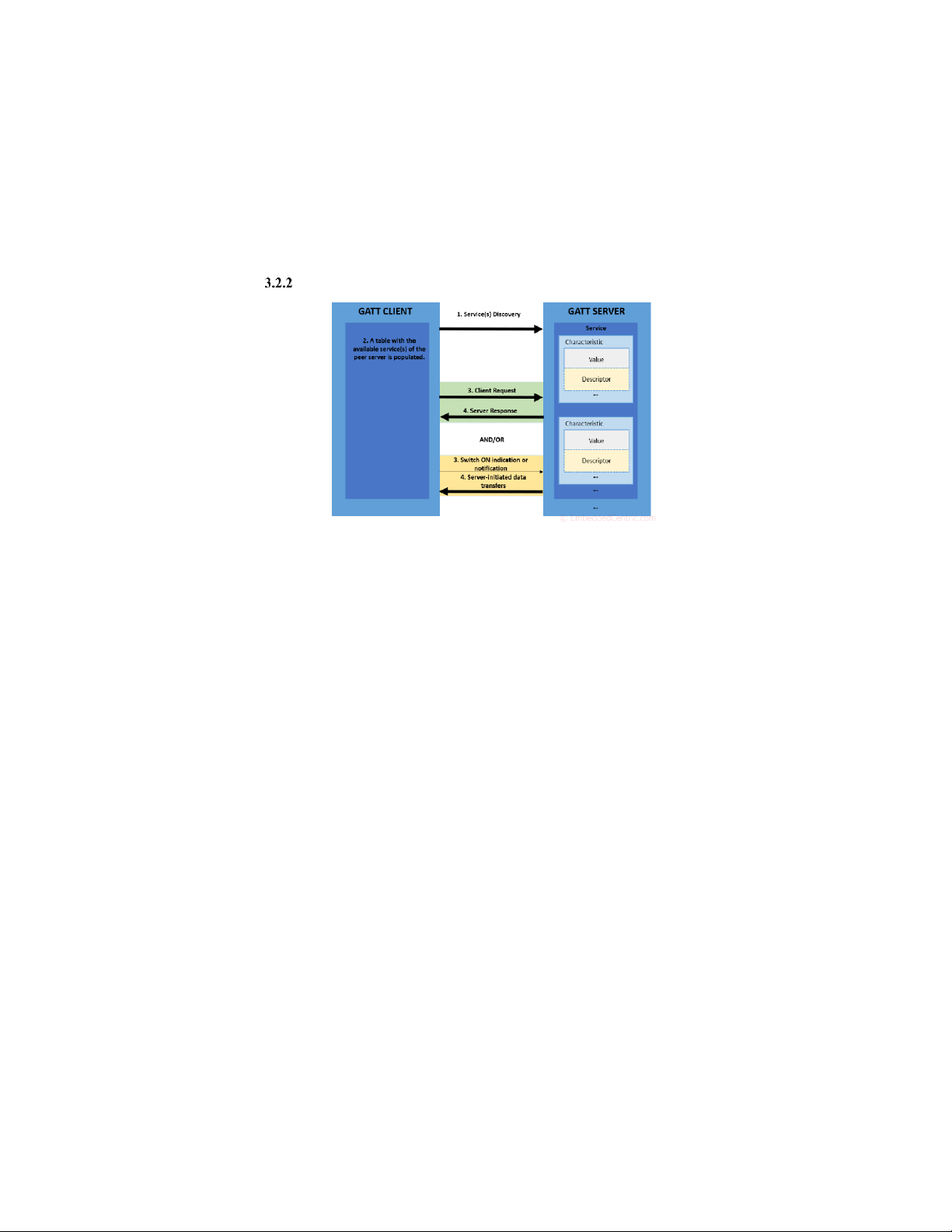
Figure 3.2 GATT Client/Server Connection • Server Device:
The server device advertises its presence to nearby devices. This
advertising packet includes information about the services it offers and their characteristics.
Each service exposes one or more characteristics. These characteristics
can represent data to be read or written, notifications, or indications. The server
stores the current values of these characteristics in its attribute table. • Client Device:
The client device scans for nearby BLE advertisements to discover
available server devices. Upon discovering a server device, the client device can
initiate a connection by sending a connection request. • Connection Establishment:
Once the connection is established, the client device can explore the
services and characteristics offered by the server device. It does this by sending
GATT requests to read or write characteristic values, enable notifications, or
discover services and characteristics. • Data Exchange: 7
The client can read values from characteristics or write values to them as
needed. For characteristics that support notifications or indications, the client can
request to be notified when the value changes. This al ows for real-time updates when the server data changes. 8 CHAPTER 4. SYSTEM DESIGN 4.1 Overal System Design
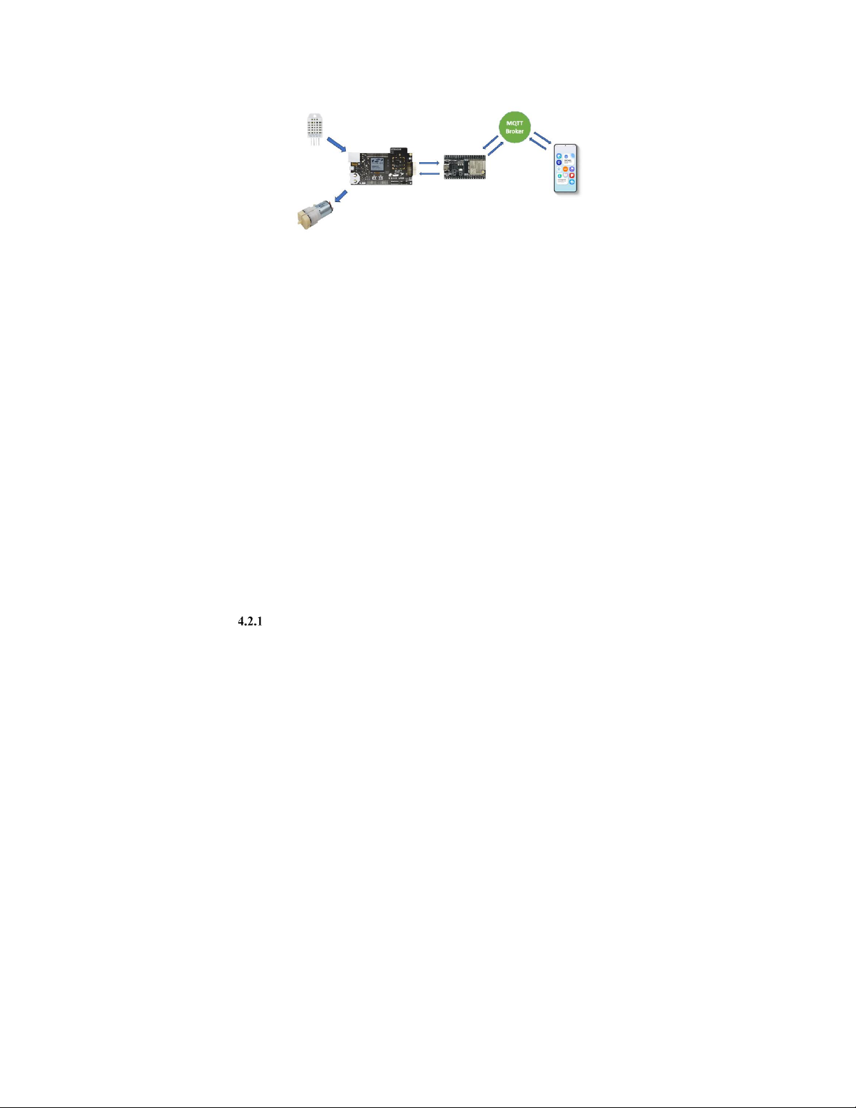
Figure 4.1 The overall system during operation System Operation:
Sending Data from the product to the Server and Displaying it on the app:
• Step 1: The EFR32MG24 prokit sends data to the ESP32 module via BLE (with preconfigured UUID).
• Step 2: Configure the ESP32's Wi-Fi to connect to the home network via smart config.
• Step 3: The ESP32 retrieves signals from the garden and sends them to the MQTT server via MQTT.
• Step 4: The Android app retrieves server data to display on the user interface.
Control via Android App or Website:
• Step 1: The Android app sends control commands to the server via MQTT.
• Step 2: The server receives the control commands and forwards them to the ESP32.
• Step 3: The ESP module receives the control commands, processes them,
and sends them to the central processing unit via BLE.
• Step 4: The central processing unit converts the received signals into
on/off signals for the devices.
4.2 Functionality and Block Diagram Functions of the System
- Control hardware devices through the Internet via the Android app.
- Display environmental parameters such as air temperature, humidity,
nutrient concentration, and pH level of the water in the plant pot.
- Send notifications when the water level fal s below the required level for the plants.
- Automatical y supplement nutrients when the nutrient concentration is
lower than the required level for the plants. 9 Block Diagram
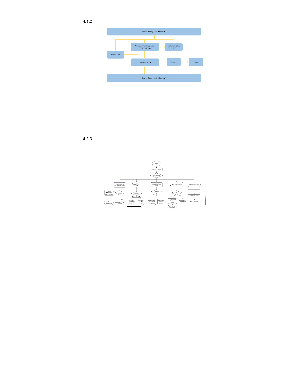
Figure 4.2 System Block Diagram
In the block diagram, we can see the power supply block providing energy
to the central processing unit, communication, sensor, and output blocks.
The central processing unit block wil retrieve data from the sensor block,
communicate with the communication block to push data to the server and display it on the app.
The output block also receives commands from the central processing unit
block, which can be initiated from the app or through initial settings. Algorithm Flowchart
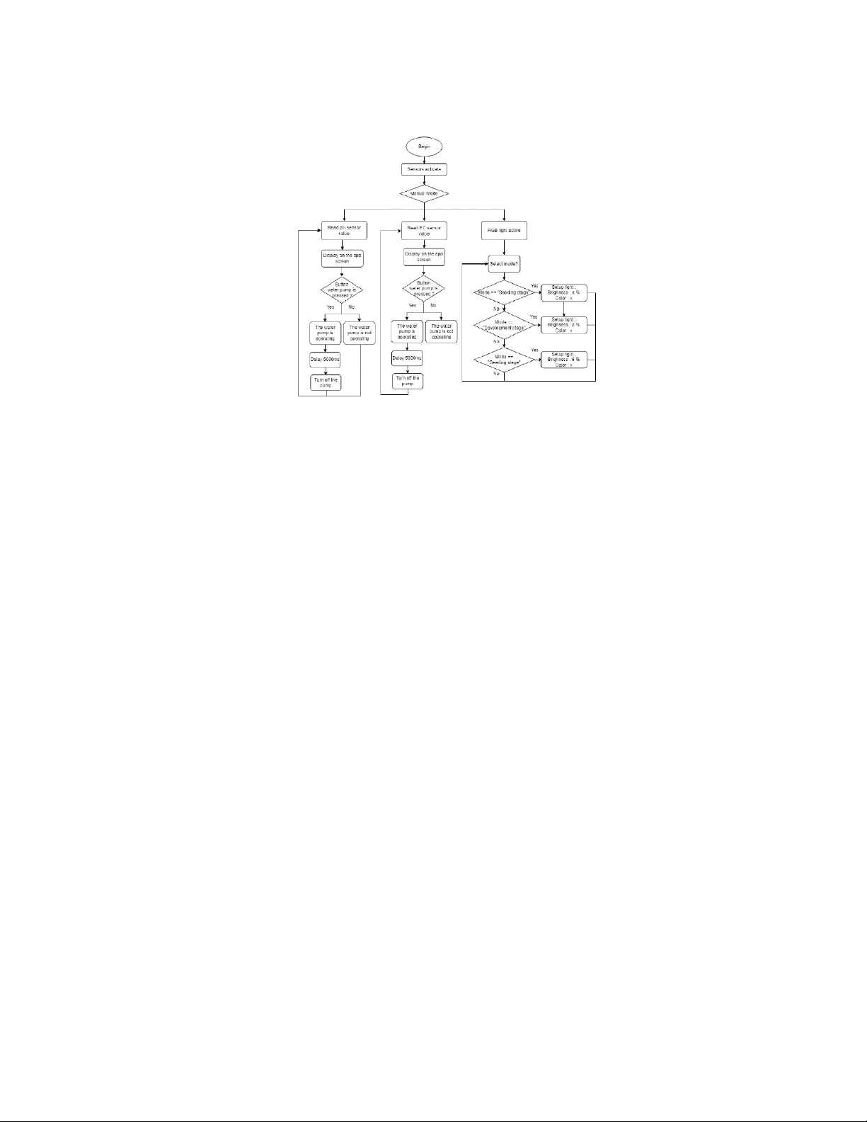
The Smart Indoor Garden system wil have two selectable modes that can
be configured through the app. a) Automatic Mode
Figure 4.3 The algorithm flowchart for the Automatic Mode
When the auto mode is set, the values of the pH, EC, DHT, and XKC
sensors are read, and their operating conditions are checked as fol ows:
- If the temperature and humidity sensors detect values outside the al owed
range, a notification wil be displayed.
- If the Ph and EC sensors detect values outside the al owed range, the
nutrient pump wil be automatical y activated to adjust the nutrient levels in the water. 10
- If the water level sensor detects values outside the al owed range, a
warning wil be sent through the app.
- The air pump wil automatical y turn off with a cycle of 2 hours on and 12 hours off. b) Manual Mode
Figure 4.4 The algorithm flowchart for the Manual Mode
We can control the system through the app, enabling us to:
Nutrient Pump Control: Control the nutrient pump valve to dissolve
nutrients into the water. Each press of the button wil release nutrients for 5 seconds.
Light Control: Adjust the lighting of the grow lights using buttons to suit
the plant's developmental stages: germination, growth, and development. 11
4.3 Hardware Design in the System Selection of Used Devices
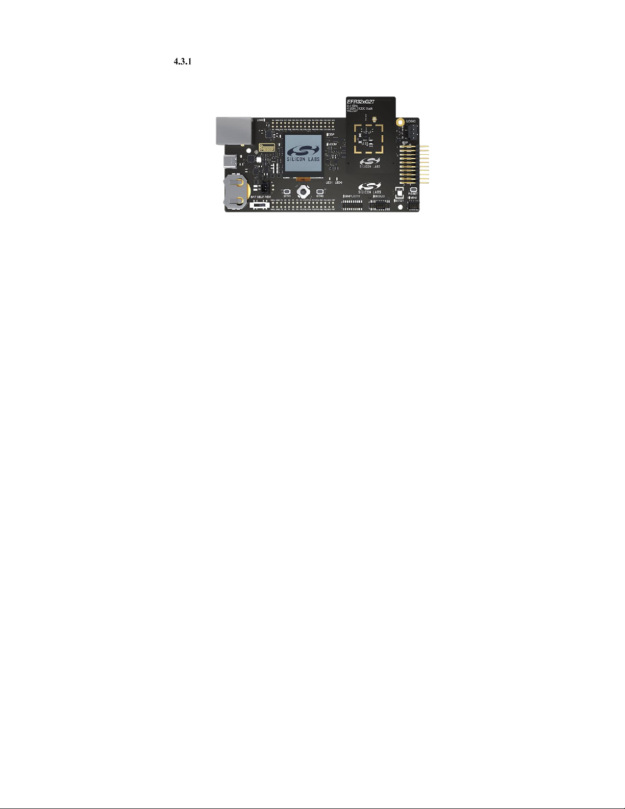
4.3.1.1. Silicon Labs EFR32xG24 Pro Kit
Figure 4.5 Silicon Labs EFR32xG24 Pro Kit
The EFR32xG24 Pro Kit is a compact IoT development platform based on
Silicon Labs' EFR32MG24 System-on-Chip. This kit is designed for prototyping
and testing IoT applications using wireless protocols such as Bluetooth LE,
Zigbee, Thread, and Matter in the 2.4 GHz range. Its key features include a USB
interface, integrated SEGGER J-Link debugger, packet trace interface, push
buttons, and support for hardware expansion through mikroBus sockets and
Qwi c® connectors, offering flexibility in IoT application development and testing.
Some key technical specifications: - CPU: Cortex-M14.
- Operating frequency: Typical y 40 MHz or 72 MHz.
- Wireless connectivity standards supported: BLE, Zigbee, Thread, Wi-Fi.
- I/O interface: GPIO pins for connecting peripherals and sensors.
- Communication interfaces: UART, SPI, I2C, USB, CAN, USART, PWM, ADC, DAC. - Power supply: 2.0~3.8V.
- Operating temperature: -40~85°C or -40°C~105°C.
- Operating system: Can run on embedded systems like Micrium, FreeRTOS, etc.
Additional y, it offers low power consumption, and security features and
leverages the Silicon Labs ecosystem, providing flexibility for various IoT applications. 12 4.3.1.2. ESP32 Figure 4.6 ESP32
The ESP32 is a series of low-cost, low-power microcontrol ers with built-in
Wi-Fi and dual-mode Bluetooth support. ESP32 devices are powered by the
Tensilica Xtensa LX6 processor, available in both dual-core and single-core
variants. They come equipped with integrated antenna switches, RF balun, power
amplifiers, low-noise amplifiers, filters, and power management modules.
Some key technical specifications:
- CPU: Xtensa Dual–Core LX6 microprocessor.
- Operating frequency: Typical y 80 MHz or 160 MHz.
- Wireless communication support: Wi-Fi and Bluetooth (BLE).
- I/O interface: GPIO pins for connecting and interacting with peripherals and sensors.
- Embedded operating system support: It can run embedded operating systems like FreeRTOS.
- Operating voltage: 2.2~3.6V.
- Operating temperature: -40~85°C. - Number of GPIO pins: 34.
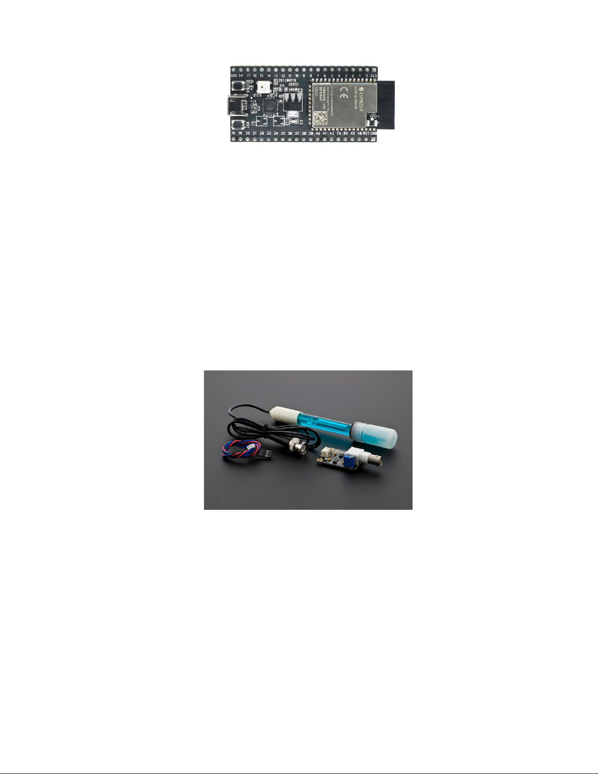
4.3.1.3. DFRobot Gravity pH meter V1.1
Figure 4.7 DFRobot Gravity pH meter V1.1 13
Tài liệu liên quan:
-
Báo cáo Thực Tập Cơ Bản: Linh Kiện và IC Trong Mạch Điện | Thực tập cơ bản | Trường Đại học Bách khoa Hà Nội
41 21 -
Báo cáo Thực Tập Cơ Bản: Thiết Kế Mạch Điện Tử | Thực tập cơ bản | Trường Đại học Bách khoa Hà Nội
35 18 -
Báo cáo về Chủ nghĩa Xã hội Khoa học và Vai trò của C. Mác - Ph. Ăngghen | Thực tập cơ bản | Trường Đại học Bách khoa Hà Nội
40 20 -
Báo cáo Thực Tập Cơ Bản: Thiết Kế Mạch Đếm Thuận 0-9 Bằng Altium | Thực tập cơ bản | Trường Đại học Bách khoa Hà Nội
35 18 -
Báo cáo thực tập Mạch khuếch đại âm tần - Điện tử | Thực tập cơ bản | Trường Đại học Bách khoa Hà Nội
38 19