core auro cho lap trinh may tinh
core auro cho lap trinh may tinh
Môn: Toán cho các nhà kinh tế 72 tài liệu
Trường: Trường Đại học Kinh Tế Quốc Dân 8.2 K tài liệu
Tác giả:


Preview text:
Aurora 64B/66B v13.0
LogiCORE IP Product Guide
Vivado Design Suite
PG074 (v13.0) December 11, 2024
AMD Adaptive Computing is creating an environment where
employees, customers, and partners feel welcome and included.
To that end, we’re removing non-inclusive language from our
products and related collateral. We’ve launched an internal
initiative to remove language that could exclude people or
reinforce historical biases, including terms embedded in our
software and IPs. You may still find examples of non-inclusive
language in our older products as we work to make these
changes and align with evolving industry standards. Follow this link for more information. Table of Contents
Chapter 1: Introduction.............................................................................................. 4
Features........................................................................................................................................4
IP Facts..........................................................................................................................................5
Chapter 2: Overview......................................................................................................6
Navigating Content by Design Process.................................................................................... 6
Core Overview..............................................................................................................................6
Applications..................................................................................................................................8
Unsupported Features................................................................................................................8
Licensing and Ordering.............................................................................................................. 9
Chapter 3: Product Specification......................................................................... 10
Performance.............................................................................................................................. 11
Resource Use............................................................................................................................. 13
Port Descriptions.......................................................................................................................13
Chapter 4: Designing with the Core...................................................................58
General Design Guidelines.......................................................................................................58
Clocking...................................................................................................................................... 58
Reset and Power Down.............................................................................................................62
Shared Logic.............................................................................................................................. 69
Using CRC...................................................................................................................................72
Hot Plug Logic............................................................................................................................72
Clock Compensation Logic.......................................................................................................72
Using Little Endian Support..................................................................................................... 73
Chapter 5: Design Flow Steps.................................................................................75
Customizing and Generating the Core...................................................................................75
GUI Options Tab for Versal Devices........................................................................................ 91
Constraining the Core...............................................................................................................94
Simulation.................................................................................................................................. 98
Synthesis and Implementation................................................................................................99
PG074 (v13.0) December 11, 2024 Aurora 64B/66B Send Feedback 2
Chapter 6: Example Design................................................................................... 100
Directory and File Contents................................................................................................... 100
Quick Start Example Design...................................................................................................100
Detailed Example Design....................................................................................................... 101
Using Vivado Lab Edition........................................................................................................104
Implementing the Example Design...................................................................................... 104
Hardware Reset FSM in the Example Design.......................................................................105
Chapter 7: Test Bench...............................................................................................108
Appendix A: Verification, Compliance, and Interoperability.............110
Appendix B: Upgrading........................................................................................... 112
Device Migration..................................................................................................................... 112
Upgrading in the Vivado Design Suite..................................................................................113
Migrating Legacy (LocalLink based) Aurora 64B/66B Cores to the AXI4-Stream
Aurora 64B/66B Core......................................................................................................... 117
Appendix C: Debugging...........................................................................................124
Finding Help with AMD Adaptive Computing Solutions.....................................................124
Debug Tools............................................................................................................................. 126
Simulation Debug....................................................................................................................126
Hardware Debug..................................................................................................................... 128
Design Bring-Up on the KC705 Evaluation Board............................................................... 133
Interface Debug...................................................................................................................... 133
Appendix D: Generating a GT Wrapper File from the Transceiver
Wizard........................................................................................................................... 134
Appendix E: Aurora 64B/66B Characterization...........................................135
Appendix F: Additional Resources and Legal Notices............................139
Finding Additional Documentation.......................................................................................139
Support Resources..................................................................................................................140
References................................................................................................................................140
Revision History.......................................................................................................................141
Please Read: Important Legal Notices................................................................................. 146
PG074 (v13.0) December 11, 2024 Aurora 64B/66B Send Feedback 3 Chapter 1: Introduction Chapter 1 Introduction
The AMD LogiCORE™ IP Aurora 64B/66B core is a scalable, lightweight, high data rate link-layer
protocol for high-speed serial communication. The protocol is open and can be implemented
using an AMD device technology.
The AMD Vivado™ Design Suite produces source code for Aurora 64B/66B cores. The cores can
be simplex or full-duplex, featuring one of two simple user interfaces, and optional flow control. Features
• General-purpose data channels with throughput ranging from 500 Mb/s to over 400 Gb/s.
• Supports up to 16 consecutively bonded 7 series GTX/GTH, AMD UltraScale™ GTH/GTY or
AMD UltraScale+™ GTH/GTY, or AMD Versal™ GTY/GTYP/GTM (NRZ line rate) transceivers.
• The GT subcore is also available outside the Aurora core.
• Aurora 64B/66B protocol specification v1.3 compliant (64B/66B encoding).
• Low resource cost with very low (3%) transmission overhead.
• Easy-to-use AXI4-Stream based framing and flow control interfaces.
• Automatically initializes and maintains the channel.
• Full-duplex or simplex operation.
• 32-bit Cyclic Redundancy Check (CRC) for user data.
• Added support for the Simplex Auto Link Recovery feature.
• Supports RX polarity inversion.
• Big endian/little endian AXI4-Stream user interface.
• Fully compliant AXI4-Lite DRP interface.
• Configurable DRP and INIT clock.
• Single-ended or differential clocking options for GTREFCLK and core INIT_CLK.
PG074 (v13.0) December 11, 2024 Aurora 64B/66B Send Feedback 4
Chapter 1: Introduction IP Facts
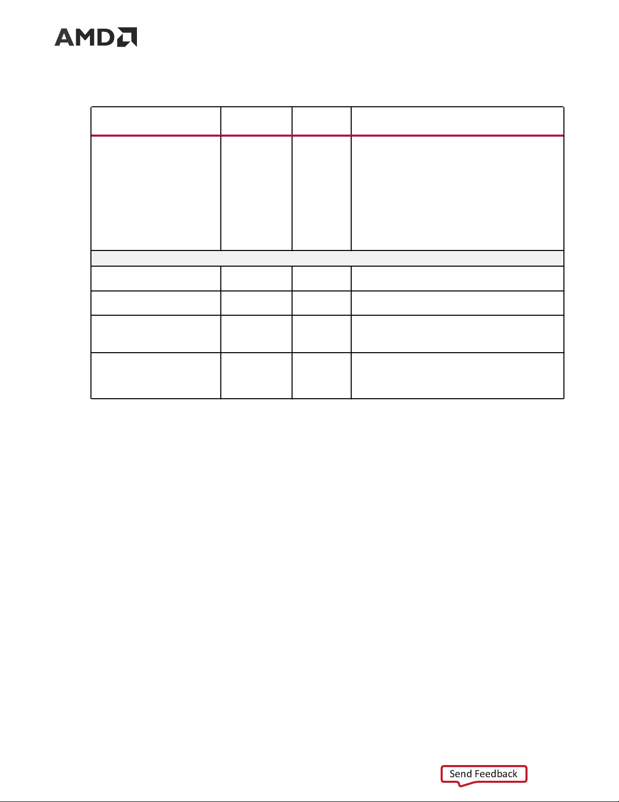
AMD LogiCORE™ IP Facts Table Core Specifics Supported Device Family1
AMD Versal™ adaptive SoC, AMD UltraScale+™, AMD Zynq™ 7000, AMD Virtex™ 7, AMD Kintex™ 7 Supported User Interfaces AXI4-Stream Resources
Performance and Resource Use web page Provided with Core Design Files Verilog Example Design Verilog4 Test Bench Verilog Constraints File
Xilinx Design Constraints (XDC) Simulation Model
Source HDL with SecureIP transceiver simulation models Supported S/W Driver2 N/A Tested Design Flows5 Design Entry AMD Vivado™ Design Suite Simulation
For supported simulators, see the Vivado Design Suite User Guide: Release Notes,
Installation, and Licensing (UG973). Synthesis Vivado Synthesis Support Release Notes and Known Issues Master Answer Record: 21263 All Vivado IP Change Logs
Master Vivado IP Change Logs: 72775 Support web page Notes: 1.
For a complete list of supported devices, see the AMD Vivado™ IP catalog. 2.
For more information on supported device family, see References. 3.
For more complete performance data, see Performance. 4.
The IP core is delivered as Verilog source code. A mixed-language simulator is required for example design
simulation because of subcore dependencies. 5.
For the supported versions of the tools, see the AMD Vivado™ Design Suite User Guide: Release Notes, Installation,
and Licensing. Refer to Vivado Design Suite User Guide: Release Notes, Installation, and Licensing (UG973).
PG074 (v13.0) December 11, 2024 Aurora 64B/66B Send Feedback 5 Chapter 2: Overview Chapter 2 Overview
Navigating Content by Design Process
AMD Adaptive Computing documentation is organized around a set of standard design
processes to help you find relevant content for your current development task. You can access
the AMD Versal™ adaptive SoC design processes on the Design Hubs page. You can also use the
Design Flow Assistant to better understand the design flows and find content that is specific to
your intended design needs. This document covers the following design processes:
• Hardware, IP, and Platform Development: Creating the PL IP blocks for the hardware
platform, creating PL kernels, functional simulation, and evaluating the AMD Vivado™ timing,
resource use, and power closure. Also involves developing the hardware platform for system
integration. Topics in this document that apply to this design process include: • Port Descriptions • Clocking • Reset and Power Down
• Customizing and Generating the Core • Chapter 6: Example Design Core Overview
This product guide describes the function and operation of the AMD LogiCORE™ IP Aurora
64B/66B core and provides information about designing, customizing, and implementing the core.
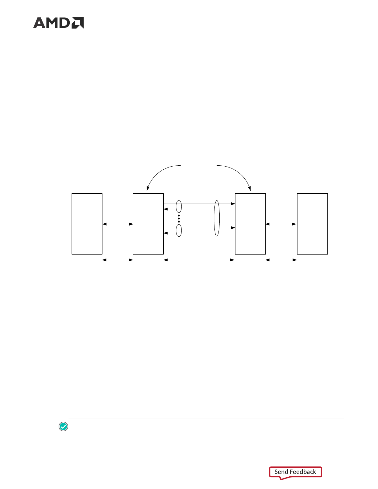
Aurora 64B/66B is a lightweight, serial communications protocol for multi-gigabit links (as shown
in the following figure). It is used to transfer data between devices using one or many GTX, GTH,
or GTY (GTYE4,GTYE5,GTYP and GTM) transceivers. Connections can be full-duplex (data in
both directions) or simplex (data in either one of the directions).
PG074 (v13.0) December 11, 2024 Aurora 64B/66B Send Feedback 6 Chapter 2: Overview
The Aurora 64B/66B core supports the AMBA® protocol AXI4-Stream user interface. It
implements the Aurora 64B/66B protocol using the high-speed serial GTX, GTH, GTYE4, GTYE5,
GTYP and GTM transceivers in applicable AMD Versal™, AMD UltraScale+™, AMD UltraScale™,
AMD Zynq™ 7000, AMD Virtex™ 7, and AMD Kintex™ 7 devices. A single instance of Aurora
64B/66B core can use up to 16 valid consecutive lanes on GTX, GTH, GTYE4, GTYE5, GTYP and
GTM transceivers running at any supported line rate to provide a low-cost, general-purpose, data
channel with throughput from 500 Mb/s to over 400 Gb/s.
Aurora 64B/66B cores are verified for protocol compliance using an array of automated simulation tests.
Figure 1: Aurora 64B/66B Channel Overview Aurora Channel Partners Aurora Aurora Lane 1 Channel User User Aurora Aurora User Interface Interface 64B/66B 64B/66B User Application Core Core Application Aurora Lane n User Data User Data 64B/66B Encoded Data X13011
Aurora 64B/66B cores automatically initialize a channel when they are connected to an Aurora
64B/66B channel partner. After initialization, applications can pass data across the channel as
frames or streams of data. Aurora 64B/66B frames can be of any size. A high-priority request is
capable of interrupting these frames at any time. Gaps between valid data bytes are
automatically filled with idles to maintain a lock and prevent excessive electromagnetic
interference. Flow control is optional in Aurora 64B/66B and can be used to throttle the link
partner’s transmit data rate, or to send brief high-priority messages through the channel.
Streams are implemented in Aurora 64B/66B as a single unending frame. Whenever data is not
being transmitted, idles are transmitted to keep the link alive. Excessive bit errors,
disconnections, or equipment failures cause the core to reset and attempt to initialize a new
channel. The Aurora 64B/66B core can support a maximum of two symbols skew in the receipt
of a multi-lane channel. The Aurora 64B/66B protocol uses 64B/66B encoding. The 64B/66B
encoding offers theoretically improved performance because of its very low (3%) transmission
overhead, compared to 25% overhead for 8B/10B encoding. RECOMMENDED:
PG074 (v13.0) December 11, 2024 Aurora 64B/66B Send Feedback 7 Chapter 2: Overview
• Although the Aurora 64B/66B core is a fully-verified solution, the challenge associated with
implementing a complete design varies depending on the configuration and functionality of the
application. For best results, prior experience in building high-performance, pipe lined FPGA
designs using the AMD implementation tools and Xilinx Design Constraints (XDC) user
constraints files is recommended.
• Consult the PCB design requirements information in UltraScale Architecture GTH Transceivers User
Guide (UG576), UltraScale Architecture GTY Transceivers User Guide (UG578), 7 Series FPGAs
GTX/GTH Transceivers User Guide (UG476), Versal Adaptive SoC GTY and GTYP Transceivers
Architecture Manual (AM002), and Versal Adaptive SoC GTM Transceivers Architecture Manual
(AM017). Contact your local AMD representative for a closer review and estimation for your specific requirements. Applications
Aurora 64B/66B cores can be used in a wide variety of applications because of their low
resource cost, scalable throughput, and flexible data interface. Examples of Aurora 64B/66B core applications include:
• Chip-to-chip links: Replacing parallel connections between chips with high-speed serial
connections can significantly reduce the number of traces and layers required on a PCB.
• Board-to-board and backplane links: Aurora 64B/66B uses standard 64B/66B encoding, that
is the preferred encoding scheme for 10 Gigabit Ethernet, making it compatible with many
existing hardware standards for cables and backplanes. Aurora 64B/66B can be scaled in line
rate and channel width to allow the usage of inexpensive legacy hardware in new, high- performance systems.
• Simplex connections (unidirectional): The Aurora 64B/66B simplex protocol provides
unidirectional channel initialization, which makes the usage of the GTX, GTH, and GTY
transceivers possible when a back channel is not available, and reduces the cost due to unused full-duplex resources. Unsupported Features
• AXI4-Stream non-strict aligned mode is not supported in the Aurora 64B/66B core.
• GTP and GTZ type transceivers of 7 series devices are not supported in the Aurora 64B/66B core.
• Aurora 64B/66B supports the UFC feature only in GTYE3/GTYE4 devices up to 16.375G.
PG074 (v13.0) December 11, 2024 Aurora 64B/66B Send Feedback 8 Chapter 2: Overview
• Dynamic switching of Line rates in the case of GTHE4/GTYE4 and CPLL configurations using
DRP's, might not work as expected because of the updates made around GTHE4/GTYE4
CPLL Calibration module inside the gtwizard_ultrascale IP. For more information, see
UltraScale FPGAs Transceivers Wizard LogiCORE IP Product Guide (PG182). For more information
on Versal Adaptive SoC GT, see Versal Adaptive SoC GTY and GTYP Transceivers Architecture
Manual (AM002) and Versal Adaptive SoC GTM Transceivers Architecture Manual (AM017). Licensing and Ordering
This AMD LogiCORE™ IP module is provided at no additional cost with the AMD Vivado™
Design Suite under the terms of the End User License.
Information about other AMD LogiCORE™ IP modules is available at the Intellectual Property
page. For information about pricing and availability of other AMD LogiCORE IP modules and
tools, contact your local sales representative.
For more information, visit the Aurora 64B/66B product page. License Checkers
If the IP requires a license key, the key must be verified. The AMD Vivado™ design tools have
several license checkpoints for gating licensed IP through the flow. If the license check succeeds,
the IP can continue generation. Otherwise, generation halts with an error. License checkpoints
are enforced by the following tools: • Vivado Synthesis • Vivado Implementation
• write_bitstream (Tcl command)
IMPORTANT! IP license level is ignored at checkpoints. The test confirms a valid license exists. It does not check IP license level.
PG074 (v13.0) December 11, 2024 Aurora 64B/66B Send Feedback 9
Chapter 3: Product Specification Chapter 3 Product Specification
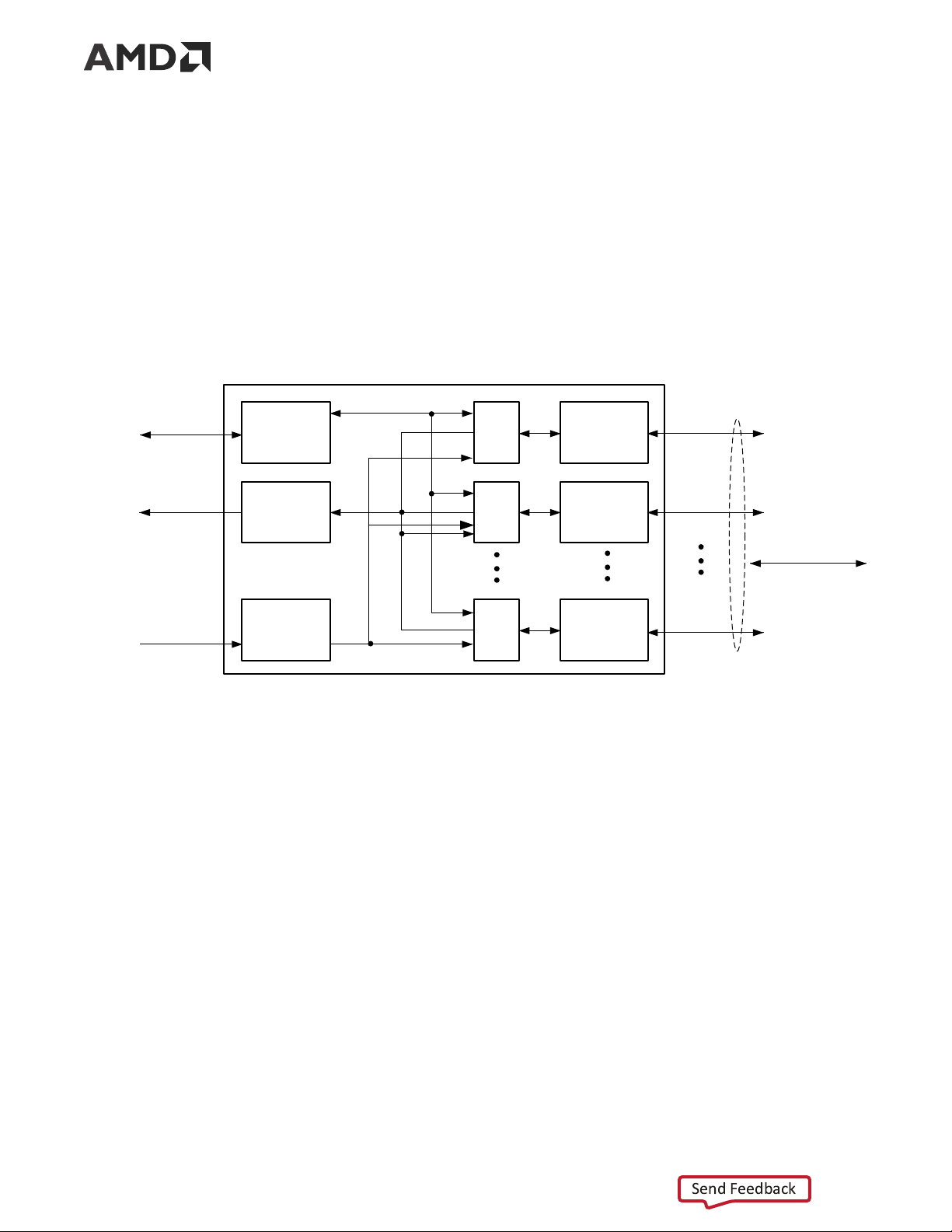
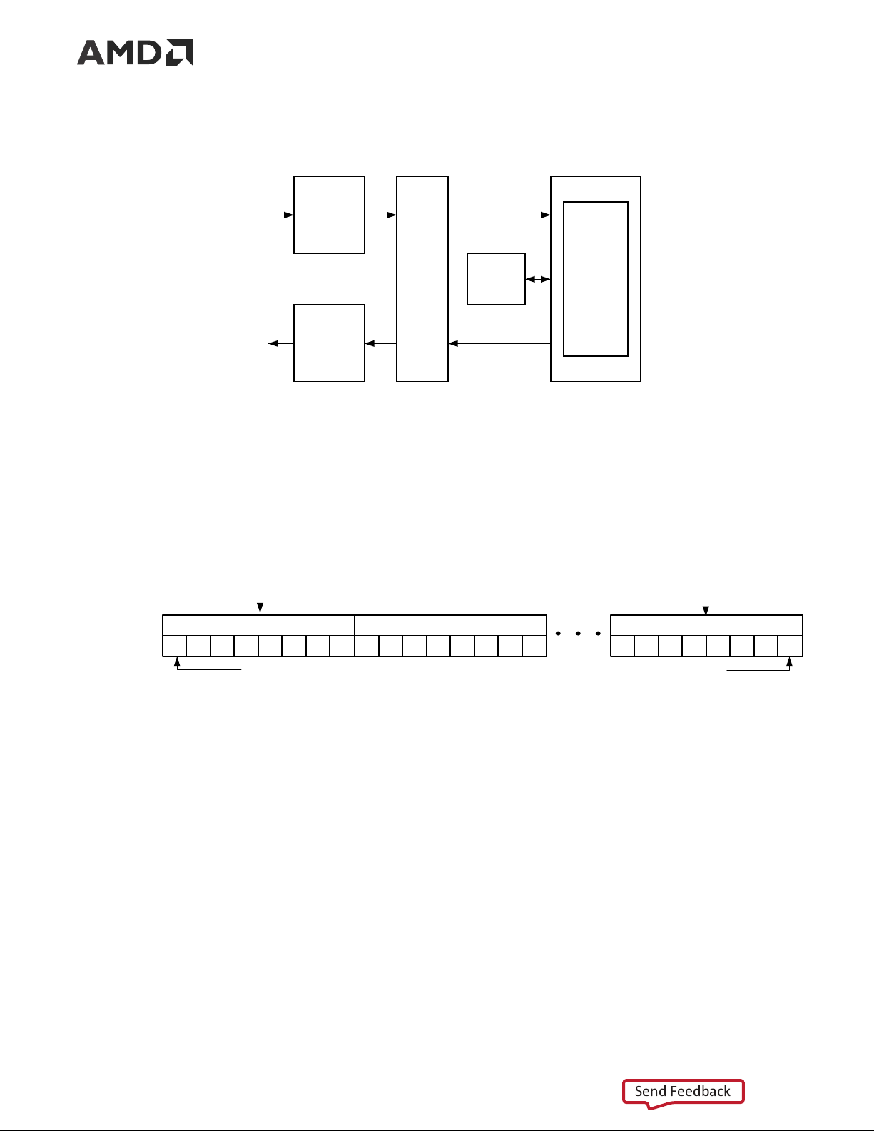
The functional block diagram of the core is shown in the following figure.
Figure 2: Aurora 64B/66B Core Block Diagram Control Serial I/O Global Logic Interface GTX/GTH/ Lane Lane 1 (Channel GTY 1 Maintenance) Logic (Lane 1) RX User Serial I/O GTX/GTH/ RX Data Interface Lane Lane 2 GTY 2 (Framing or Logic Streaming) (Lane 2) Aurora Channel Serial I/O TX User Serial I/O GTX/GTH/ Interface Lane Lane n GTY n TX Data (Framing or Logic Streaming) (Lane n) X13012
The major functional modules of the Aurora 64B/66B core are:
• Lane logic: An instance of the lane logic module drives each GT transceiver. This lane logic
initializes each individual transceiver, handles the encoding and decoding of control
characters, and performs error detection.
• Global logic: The global logic module in the core performs the channel bonding for channel
initialization. During operation, the channel keeps track of the Not Ready idle characters
defined by the Aurora 64B/66B protocol and monitors all the lane logic modules for errors.
• RX user interface: The AXI4-Stream receive (RX) user interface moves data from the channel
to the application and also performs flow control functions.
• TX user interface: The AXI4-Stream transmit (TX) user interface moves data from the
application to the channel and also performs flow control TX functions. The standard clock
compensation module is embedded inside the core. This module controls the periodic
transmission of the clock compensation (CC) character.
PG074 (v13.0) December 11, 2024 Aurora 64B/66B Send Feedback 10
Chapter 3: Product Specification Performance
This section details the performance information for various core configurations. Maximum Frequencies
The maximum frequency of the core operation is dependent on the line rates supported and the speed grade of the devices. Latency
For a default single lane configuration, latency through an Aurora 64B/66B core is caused by
pipeline delays through the protocol engine (PE), GTX, and GTH transceivers. The PE pipeline
delay increases as the AXI4-Stream interface width increases. The transceiver delays are
determined by the transceiver features.
This section outlines a method of measuring the latency for the Aurora 64B/66B core AXI4-
Stream user interface in terms of user_clk cycles for AMD Zynq™ 7000, AMD Virtex™ 7,
AMD Kintex™ 7 (GTX and GTH transceiver-based designs), AMD UltraScale™, and
AMD UltraScale+™ devices (GTH and GTYE4 transceiver-based designs) and AMD Versal devices
(GTYE5,GTYP and GTM transceiver-based designs). For the purposes of illustrating latency, the
Aurora 64B/66B modules are partitioned between logic in the GTX, GTH, GTY transceivers, and
protocol engine (PE) logic implemented in the FPGA.
The following figure illustrated the latency of the data path.
Figure 3: Latency of the Datapath TX AXI Interface TX_PE TX_GT RX_GT RX_PE RX AXI Interface s_axi_tx_tvalid m_axi_rx_tvalid X12663
Note: The preceding figure does not include the latency incurred due to the length of the serial connection
between each side of the Aurora 64B/66B channel.
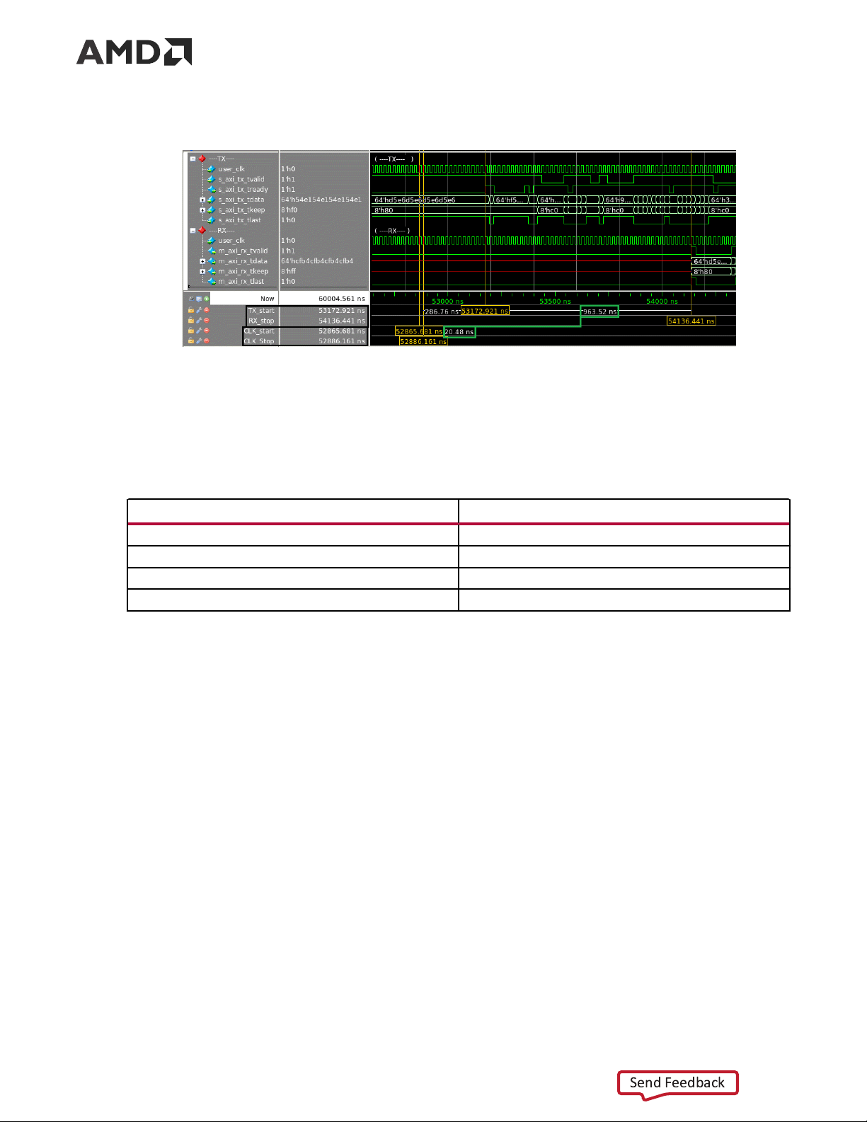
The latency must be measured from the rising edge of the transmitter user_clk at the first
assertion of s_axi_tx_tvalid and s_axi_tx_tready to the rising edge of the receiver
user_clk at the first assertion of m_axi_rx_tvalid. The following figure shows the
transmitter and receiver path reference points between which the latency has been measured for
the default core configuration.
PG074 (v13.0) December 11, 2024 Aurora 64B/66B Send Feedback 11
Chapter 3: Product Specification
Figure 4: Latency Waveform with Reference Points
The following table shows the maximum latency and the individual latency values of the
contributing pipeline components for the default core configuration on 7 series GTX/GTH and
UltraScale/UltraScale+ GTH transceiver-based devices. Latency can vary with the addition of flow controls.
Table 1: Latency for the Default Aurora 64B/66B Core Configuration Latency Component user_clk Cycles Logic 46 Gearbox 1 or 2 Clock Compensation 7 Maximum (total) 54 or 55
The pipeline delays are designed to maintain the clock speed. Throughput
Aurora 64B/66B core throughput depends on the number of transceivers, transceiver type, and
the target line rate of the selected transceivers. For GTH transceivers, the throughput varies from
0.48 Gb/s to 254.06 Gb/s for a single-lane design to a 16-lane design, respectively. For GTY
transceivers, the throughput varies from 0.455 Gb/s to 400 Gb/s with the supported line rate
range of 0.5 Gb/s to 25.7813 Gb/s. The maximum throughput for GTY might not give an
accurate lane striping difference in the design when the line rate is greater than 16.375 Gb/s.
The throughput for Versal devices GTYE5, GTYP varies from 1.163 Gb/s to 508.12 Gb/s with
supported line rate range of 1.2 Gb/s to 32.75 Gb/s for single lane to 16-lane design. The
throughput for Versal GTM (NRZ) varies from 1.163 to 449.93 Gb/s with supported line rate
range of 1.2 Gb/s to 29 Gb/s for single lane to 16-lane design. The line rates from 15 Gb/s to 19
Gb/s are invalid for Versal GTM (NRZ).
PG074 (v13.0) December 11, 2024 Aurora 64B/66B Send Feedback 12
Chapter 3: Product Specification
Note: For better timing performance when using the default Synthesis strategy from VIVADO, reduce the
line rate by around 30% from the Maximum line rate supported by IP/Transceiver. Reduce the line rate by
50% when CRC_MODE is enabled. With another suitable synthesis strategy, the user can achieve the
maximum Line rate supported in the IP. Refer to Vivado Design Suite User Guide: Synthesis (UG901).
Note: Refer Appendix E: Aurora 64B/66B Characterization for characterization details when CRC_MODE is disabled. Resource Use
For full details about performance and resource use, visit the Performance and Resource Use web page. Port Descriptions
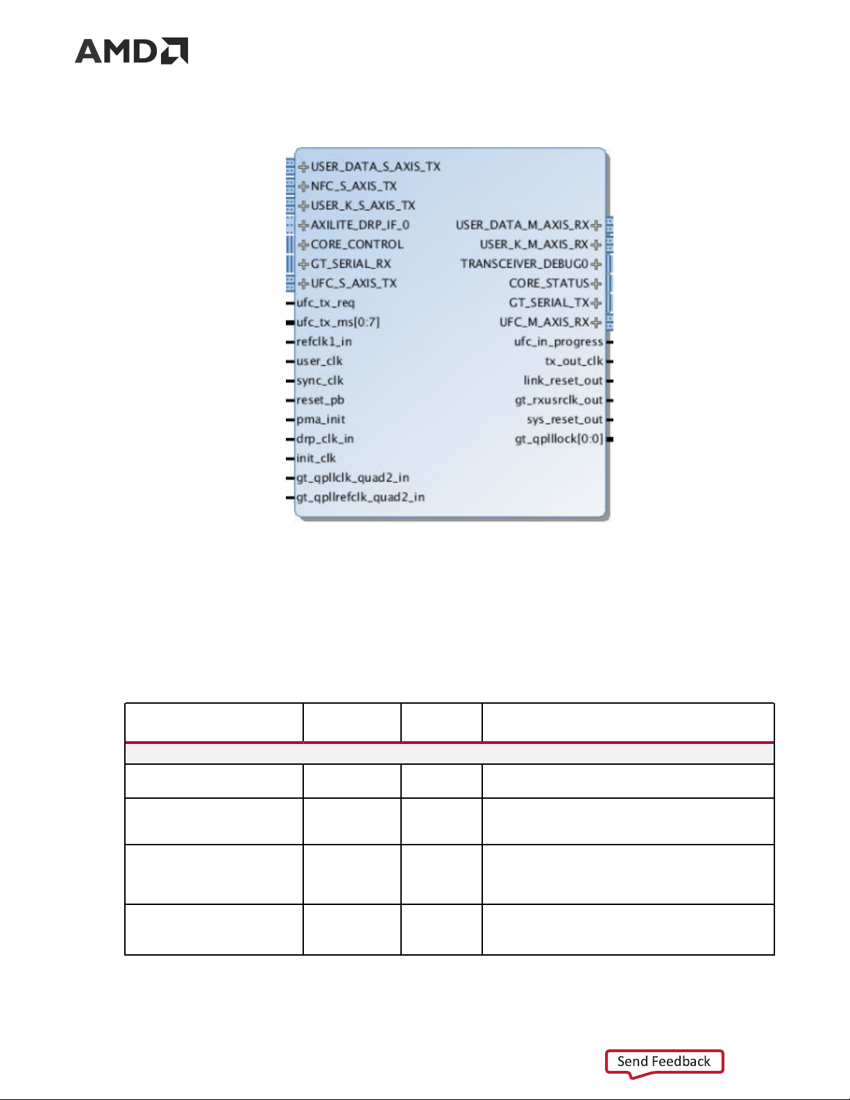
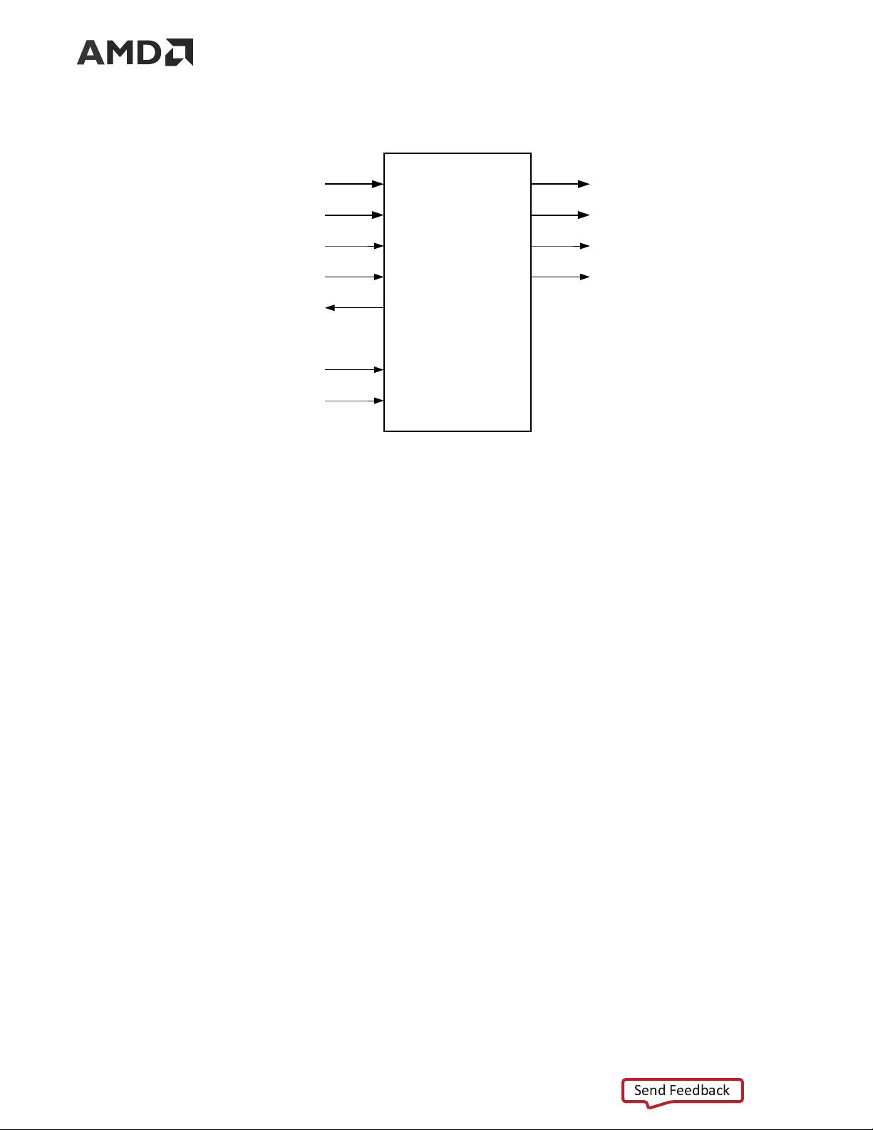
The parameters used to generate each Aurora 64B/66B core determine the interfaces available
for that specific core. USER_DATA_S_AXIS_TX is an interface and the s_axi_tx_* ports are
grouped into that interface. The interfaces are visible in the IP symbol as seen in the following
figure the ports grouped in it. In this section, in general, the interface appears as a single row
entry followed by the ports that are grouped in an interface by clicking on the + sign beside the
interface. Aurora 64B/66B cores can have four to eight interfaces. The following shows the
Aurora 64B/66B IP symbol for the default core configuration with all flow control options and CRC enabled.
PG074 (v13.0) December 11, 2024 Aurora 64B/66B Send Feedback 13
Chapter 3: Product Specification
Figure 5: Aurora 64B/66B IP Symbol User Interface Ports
Either a framing or a streaming user data interface can generate the Aurora 64B/66B core. Data
port width depends on the number of lanes selected. The following table lists simplex/duplex
port descriptions for the AXI4-Stream TX data ports.
Table 2: User Interface Ports Name Direction Clock Domain Description USER_DATA_S_AXIS_TX
s_axi_tx_tdata[0:(64n –1)] or Input user_clk
Outgoing data (ascending bit order).
s_axi_tx_tdata[(64 n –1):0](1)(2) s_axi_tx_tready(2) Output user_clk
Asserted when signals from the source are accepted.
Deasserted when signals from the source are ignored. s_axi_tx_tvalid(2) Input user_clk
Asserted when AXI4-Stream signals from the source
are valid. Deasserted when AXI4-Stream control
signals and/or data from the source should be ignored. s_axi_tx_tlast(2) Input user_clk
Indicates the end of the frame.
This port is not available if the Streaming interface option is chosen.
PG074 (v13.0) December 11, 2024 Aurora 64B/66B Send Feedback 14
Chapter 3: Product Specification
Table 2: User Interface Ports (cont'd) Name Direction Clock Domain Description
s_axi_tx_tkeep[0:(8 n –1)] or Input user_clk
Specifies the number of valid bytes in the last data
s_axi_tx_tkeep[(8 n –1):0](1)(2)
beat (number of valid bytes = number of 1s in tkeep).
s_axi_tx_tkeep is sampled only when s_axi_tx_tlast is asserted.
The core supports continuous aligned and continuous
unaligned data streams and expects data to be filled
continuously from LSB to MSB. There cannot be
invalid bytes interleaved with the valid s_axi_tx_tdata bus.
This port is not available if the Streaming interface option is chosen. USER_DATA_M_AXIS_RX
m_axi_rx_tdata[0:(64 n –1)] or Output user_clk
Incoming data from channel partner (ascending bit
m_axi_rx_tdata[(64 n –1):0](1)(3) order). m_axi_rx_tvalid(3) Output user_clk
Asserted when data from the core is valid. Deasserted
when data from the core should be ignored. m_axi_rx_tlast(3) Output user_clk
Indicates the end of the incoming frame.
This port is not available if the Streaming interface option is chosen. m_axi_rx_tkeep[0:(8n –1)] or Output user_clk
Specifies the number of valid bytes in the last data
m_axi_rx_tkeep[(8n –1):0](1)(3) beat.
This port is not available if the Streaming interface option is chosen. Notes: 1. 'n' is the number of lanes. 2.
The port is not available RX-only simplex mode. 3.
The port is not available TX-only simplex mode.
Top-Level Interface
The Aurora 64B/66B top-level (block level) file contains the top-level interface definition and is
the starting point for a user design. The top-level file instantiates the Aurora 64B/66B lane
module, the TX and RX AXI4-Stream modules, the global logic module, and the GTX, GTH, or
GTY transceiver wrapper. This top-level wrapper file is instantiated in the example design file
together with the clock, reset circuit, frame generator, and checker modules.
The following figure shows the Aurora 64B/66B top-level for a duplex configuration.
PG074 (v13.0) December 11, 2024 Aurora 64B/66B Send Feedback 15
Chapter 3: Product Specification
Figure 6: Aurora 64B/66B Duplex Top-Level Architecture Aurora 64B/66B Top Level TX GT Wrapper AXI4-Stream TX Stream Transmit User Interface Aurora Global GT Lane Logic Transceiver RX AXI4-Stream RX Stream Receive User Interface X12661
The timing requirements for the streaming and framing interfaces are described in Framing
Interface and Streaming Interface below.
The following figure shows an n -byte example of the Aurora 64B/66B AXI4-Stream data interface bit ordering.
Figure 7: AXI4-Stream Interface Bit Ordering Most Significant Byte Least Significant Byte Byte 0 Byte 1 Byte n TX_D 0 1 2 3 4 5 6 7 8 9 10 11 12 13 14 15 n0 n1 n2 n3 n4 n5 n6 n7 Most significant bit Least significant bit X13033
Framing Interface
The framing user interface (shown in the following figure) complies with the AMBA AXI4-Stream
Protocol Specification (ARM IHI 0051A) and comprises the signals necessary for transmitting and
receiving framed user data. A detailed description of the framing interface follows.
PG074 (v13.0) December 11, 2024 Aurora 64B/66B Send Feedback 16
Chapter 3: Product Specification
Figure 8: Aurora 64B/66B Framing User Interface (AXI4-Stream) s_axi_tx_tdata m_axi_rx_tdata s_axi_tx_tkeep m_axi_rx_tkeep s_axi_tx_tlast m_axi_rx_tlast s_axi_tx_tvalid m_axi_rx_tvalid Framing Interface s_axi_tx_tready reset_pb user_clk X28091-051123 Transmitting Data
The Aurora 64B/66B core samples the data only if both s_axi_tx_tready and
s_axi_tx_tvalid are asserted. The user application can deassert s_axi_tx_tvalid on any
clock cycle (Data Transfer with Pause) to ignore the AXI4-Stream input for that cycle. If this
occurs in the middle of a frame, idle symbols are sent through the Aurora 64B/66B channel.
The AXI4-Stream data is only valid when it is framed. Data outside of a frame is ignored. To end a
frame, assert s_axi_tx_tlast while the last word (or partial word) of data is on the
s_axi_tx_tdata port and use s_axi_tx_tkeep to specify the number of valid bytes in the last data beat.
High priority is assigned to these requests for any type of transfer:
• TXDATAVALID deasserted from the transceiver TX interface (1 cycle) • CC transmission (8 cycles) Aurora 64B/66B Frames
All Aurora 64B/66B data is sent as part of a data block or a separator block. A separator block
(SEP) consists of a count field indicating how many bytes are valid in that particular block. In
framing, each frame begins with data blocks and ends with a separator block containing the last
bytes of the frame. Idle blocks are inserted whenever data is not available. Blocks are eight bytes
of scrambled data or control information with a two-bit control header (a total of 66 bits).
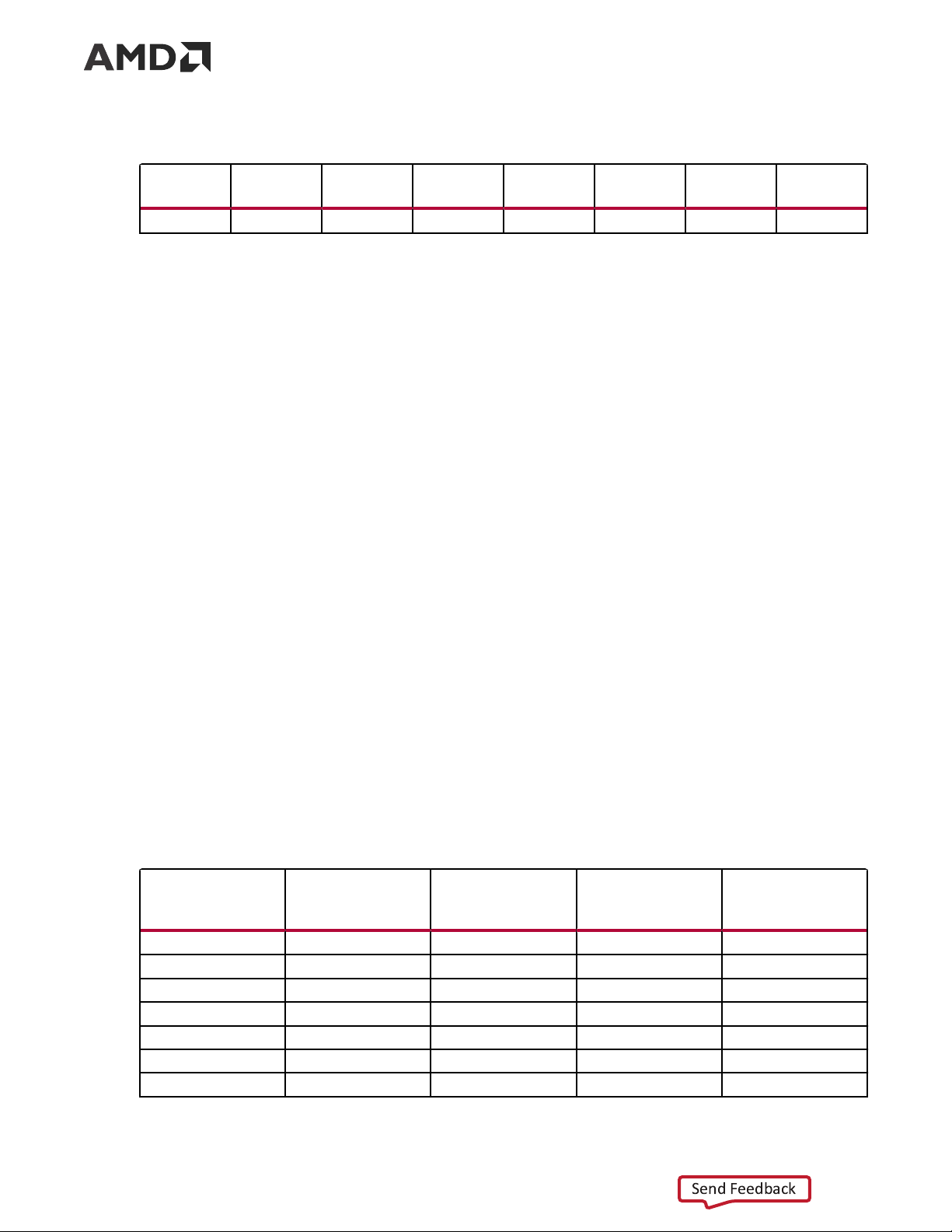
The following table shows a typical Aurora 64B/66B frame with an even number of data bytes.
PG074 (v13.0) December 11, 2024 Aurora 64B/66B Send Feedback 17
Chapter 3: Product Specification
Table 3: Typical Channel Frame
Data Byte Data Byte Data Byte Data Byte Data Byte Data Byte 0 1 2 3 . . . Data Byte n –2 n –1 n SEP (1E) Count (4) Data Byte 0 Data Byte 1 Data Byte 2 Data Byte 3 x x
To transmit the data, the user application configures the control signals causing the core to perform these steps:
1. Accept data from the user application on the s_axi_tx_tdata bus.
2. Indicate the end of the frame when s_axi_tx_tlast is asserted along with
s_axi_tx_tkeep and stripe data across lanes in the Aurora 64B/66B channel.
3. Assembles data for presentation to the user application on the m_axi_rx_tdata bus
including providing the number of valid bytes on m_axi_rx_tkeep and asserts
m_axi_rx_tvalid during the m_axi_rx_tlast cycle.
When the core receives data, it performs these steps:
1. Detects and discards control bytes (idles, clock compensation).
2. Recovers data from the lanes.
3. Assembles data for presentation to the user application on the m_axi_rx_tdata bus
including providing the number of valid bytes on m_axi_rx_tkeep and asserts
m_axi_rx_tvalid during the m_axi_rx_tlast cycle.
Data striping is handled differently for line-rates above 16.375 Gb/s. See the following table for
this packet format. Specifically, on the last cycle of a frame, all the lanes contain data blocks.
Some of these blocks can be empty or half full. On the next cycle, all the lanes transmit a SEP
block, each one containing the number of valid bytes transmitted in the previous cycle in that
lane. When using CRC, these SEP blocks also contain the 32-bit CRC for that lane over the duration of the recent frame.
Table 4: Framing Mode Packet Format of 896 Bytes Length with CRC for Line Rates > 16.375 Gb/s on 16 Lanes Data Lanes Data (first beat) (intermediate Data (last beat) Control burst) 0 8 bytes - 776 bytes sep,crc0 1 - - - sep,crc1 2 - - - sep,crc2 3 - - - sep,crc3 4 - - - sep,crc4 5 - - - sep,crc5 6 - - - sep,crc6
PG074 (v13.0) December 11, 2024 Aurora 64B/66B Send Feedback 18
Chapter 3: Product Specification
Table 4: Framing Mode Packet Format of 896 Bytes Length with CRC for Line Rates >
16.375 Gb/s on 16 Lanes (cont'd) Data Lanes Data (first beat) (intermediate Data (last beat) Control burst) 7 - - - sep,crc7 8 - - - sep,crc8 9 - - - sep,crc9 10 - - - sep,crc10 11 - - - sep,crc11 12 - - - sep,crc12 13 - - - sep,crc13 14 - - - sep,crc14 15 128 bytes - 896 bytes sep,crc15
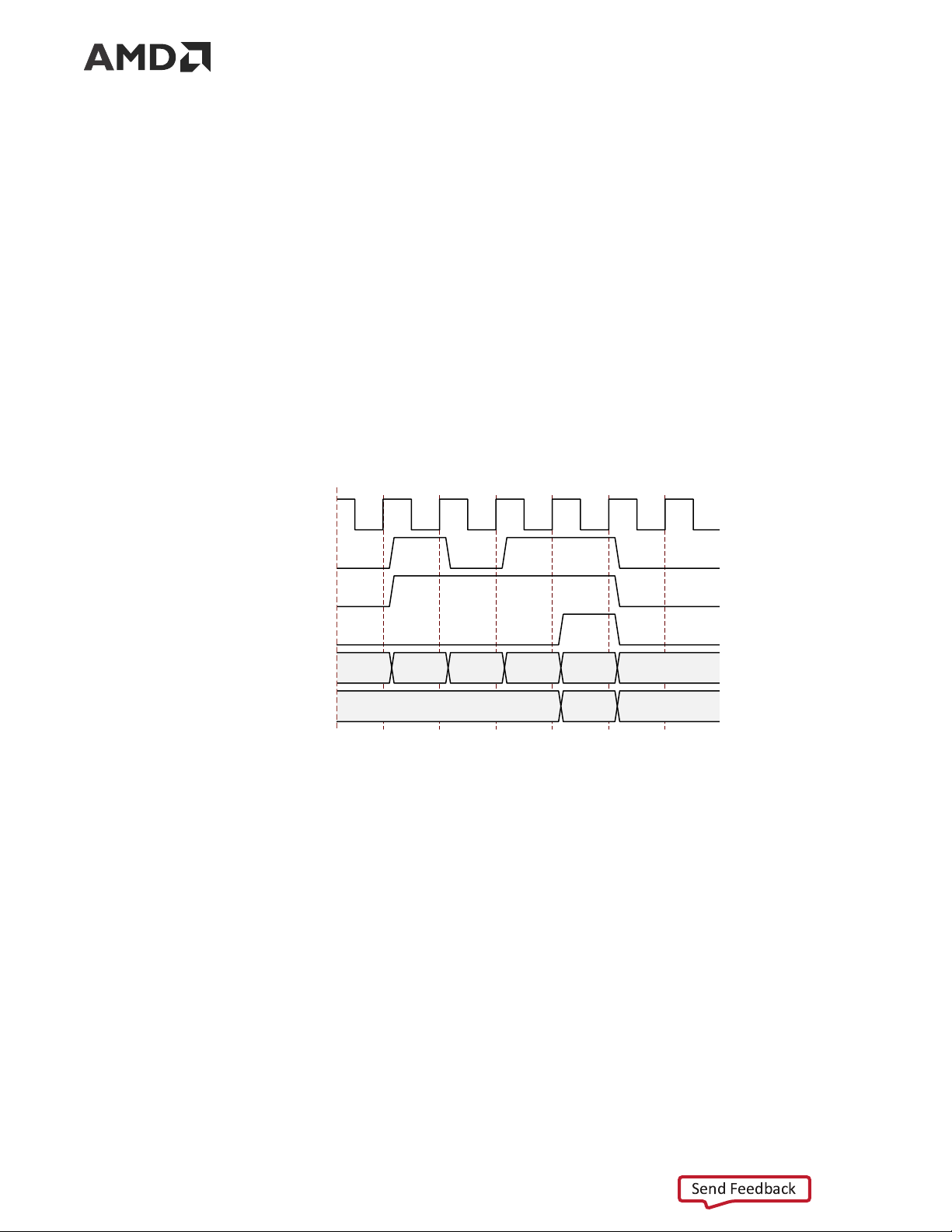
Example A: Simple Data Transfer
The following figure shows an example of a simple n byte wide data transfer. 3 n bytes of data
are sent requiring three data beats. s_axi_tx_tready is asserted indicating that the AXI4-
Stream interface is ready to transmit data.
Figure 9: Simple Data Transfer user_clk s_axi_tx_tvalid s_axi_tx_tready s_axi_tx_tlast s_axi_tx_tdata[0:(64n-1)] X Databeat 0 Databeat 1 Databeat 2 X s_axi_tx_tkeep[0:8n-1] X FF X X13044
To begin the data transfer, the user application asserts s_axi_tx_tvalid and provides the first
n bytes of the user frame. Because s_axi_tx_tready is already asserted, the data transfer
begins on the next clock edge. The data bytes are placed in data blocks and transferred through the Aurora 64B/66B channel.
PG074 (v13.0) December 11, 2024 Aurora 64B/66B Send Feedback 19
Chapter 3: Product Specification
To end the data transfer, the user application asserts s_axi_tx_tlast, s_axi_tx_tvalid,
the last data bytes, and the appropriate TKEEP value (0xFF) on the s_axi_tx_tkeep bus. The
core sends the final data word in blocks and must send an empty separator block on the next
cycle to indicate the end of the frame. s_axi_tx_tready is reasserted on the next cycle so
that more data transfers can continue. If there is no new data, the Aurora 64B/66B core sends idles.
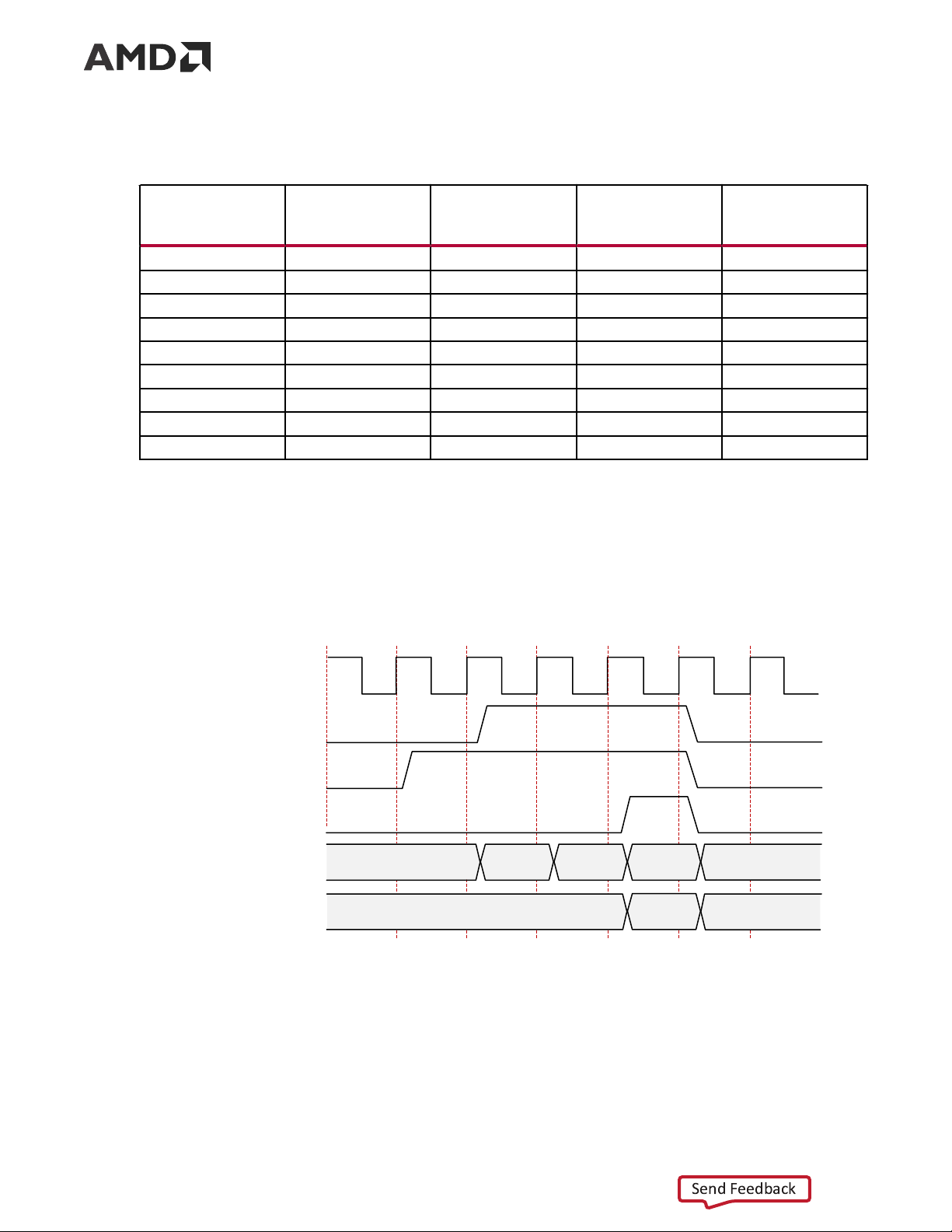
Example B: Data Transfer with Pause
The following figure shows the user application pausing data transmission during a frame
transfer. The application sends 3 n bytes of data and pauses the data flow after the first n bytes.
After the first data word, the application deasserts s_axi_tx_tvalid causing the TX to ignore
all data on the bus and transmit idle blocks. The pause continues until s_axi_tx_tvalid is asserted.
Figure 10: Data Transfer with Pause user_clk s_axi_tx_tvalid PAUSE s_axi_tx_tready s_axi_tx_tlast s_axi_tx_tdata [0:(64n-1)] X Databeat0 X Databeat1 Databeat2 X s_axi_tx_tkeep [0:8n-1] X N X X13036
Example C: Data Transfer with Clock Compensation
The following figure shows the core automatically interrupting data transmission when clock
compensation sequences are sent.
PG074 (v13.0) December 11, 2024 Aurora 64B/66B Send Feedback 20
Tài liệu liên quan:
-
Đề giữa kỳ môn Toán cho các nhà kinh tế | Trường Đại học Kinh tế Quốc dân
22 11 -

Bài giảng tóm tắt môn Toán cho các nhà kinh tế | Trường Đại học Kinh Tế Quốc Dân
32 16 -

Giáo trình Kinh tế công cộng | Trường Đại học Kinh Tế Quốc Dân
41 21 -
Chương 3. Hệ số co giãn của cầu và cung theo giá trong Kinh tế học
28 14