EE3041 DSP on FPGA Lab 2: FIR & IIR Filter Design Project môn Xử lý tín hiệu số| Đại học Bách khoa Hà Nội
The objective of this lab is to design, implement, and test a finiteimpulse response (FIR) and a infinite impulse response (IIR) filters using FPGA technology. The goal is to understand the theory behind FIR and IIR filters, apply digital filter design techniques.Tài liệu giúp bạn tham khảo, ôn tập và đạt kết quả cao. Mời đọc đón xem!
Môn: Xử lý tín hiệu số hust 33 tài liệu
Trường: Đại học Bách Khoa Hà Nội 5.8 K tài liệu
Tác giả:


Preview text:
15:02, 10/01/2026
EE3041 DSP on FPGA Lab 2: FIR & IIR Filter Design Project - Studocu
EE3041 DSP on FPGA Big Project Lab 2 - FIR and IIR Filters
Lab 2 for EE3041 DSP on FPGA Course at HCMUT
Posted Feb 6, 2025 Updated Oct 7, 2025 By Thang Luong 9 min read Lab 2 - FIR and IIR Filters Objective
The objective of this lab is to design, implement, and test a finite impulse response (FIR) and a
infinite impulse response (IIR) filters using FPGA technology. The goal is to understand the
theory behind FIR and IIR filters, apply digital filter design techniques, and gain practical
experience in hardware design and implementation. By completing this lab, students will
develop skills in FPGA programming and digital signal processing (DSP). A Note about Collaboration
The lab is to be accomplished in groups. All work must be from your own team members.
Hints from others can be of great help, both to the hinter and the hintee.
Thus, discussions and hints about the assignment are encouraged. However, the project must
be coded and written up in groups (you may not show, nor view, any source code from other
students’ groups). We WILL use automated tools to detect copying.
Use Emails/LMS to ask questions or come visit us (203B3) during office hours.
We want to see you succeed, but you have to ask for help. Overview
In this lab, students will design an FIR and IIR filters using Verilog or SystemVerilog. The focus
will be on understanding the filter design process, coding the filter architecture, and running
simulations to verify the functionality of the FIR and IIR filters. Students are required to
simulate the design to confirm its correctness.
For those seeking additional credit, there is an option to synthesize the design onto an FPGA
and perform real-time testing. This will allow students to demonstrate their filter
implementation on hardware, further reinforcing their understanding of FPGA-based digital signal processing (DSP).
The lab will include the following steps:
Understanding the theory behind FIR and IIR filter designs. 15:02, 10/01/2026
EE3041 DSP on FPGA Lab 2: FIR & IIR Filter Design Project - Studocu
Understanding the difference (pros and cons) between FIR and IIR filters.
Implementing the FIR and IIR filter architectures using Verilog and SystemVerilog.
Running simulations to verify the functionality of the filters.
Synthesizing the design on an FPGA, evaluate the synthesis result.
Conducting real-time testing, demonstration. Background FIR Filter
Finite Impulse Response (FIR) filters are an essential component in digital signal processing
(DSP) systems, widely used for tasks such as noise reduction, signal smoothing, and frequency
selection. FIR filters are known for their stability and linear phase properties, making them
suitable for various applications that require precise signal manipulation.
In digital systems, FIR filters are typically implemented using discrete-time convolutions of the
input signal with a set of filter coefficients. These coefficients determine the filter’s frequency
response, and they can be designed to pass, reject, or attenuate specific frequency bands. The
number of coefficients, or “taps,” directly impacts the filter’s performance, with more taps
generally leading to more accurate filtering but also increased computational complexity.
Below is an 8th-order direct form FIR filter. Generally, increasing the filter order (taps) improves
the filter’s performance by providing better signal filtering and more precise frequency
response. However, when implementing such a design in hardware, the issue of timing
becomes critical. Since each tap is implemented as a combinational element, the longer the
chain, the more difficult it becomes to meet timing constraints, resulting in a lower maximum operating frequency.
To address this, pipelining techniques can be applied. By introducing pipeline stages between
the taps, the combinational delay is reduced, allowing for higher clock frequencies and
improved overall performance in the hardware implementation.
The above schematic is just an example of a pipelined FIR filter. You are not required to follow
this design exactly and are encouraged to propose your own design approach. Feel free to
explore different architectures or optimizations that suit your specific implementation and performance goals. IIR Filter
An Infinite Impulse Response (IIR) filter is a digital filter that relies on both past input and
output values to produce a current output. Unlike FIR filters, which use only input values and a 15:02, 10/01/2026
EE3041 DSP on FPGA Lab 2: FIR & IIR Filter Design Project - Studocu
finite number of coefficients, IIR filters use feedback mechanisms to achieve a recursive
behavior. This makes IIR filters highly efficient for certain tasks, as they can meet frequency
response requirements with fewer coefficients than an FIR filter.
However, designing IIR filters comes with challenges, such as ensuring stability, especially when
implemented in hardware. Special care must be taken to avoid numerical instability, as small
errors or delays in feedback can cause the filter to oscillate or behave unpredictably.
Below is a general block diagram of an IIR filter structure:
IIR filters are used for tasks such as smoothing, noise reduction, and frequency band selection,
often in applications where real-time signal processing is required. Their recursive nature allows
them to efficiently implement low-pass, high-pass, band-pass, or band-stop filters. Assignment Overview
In this lab assignment, you will design and simulate FIR and IIR filters using Verilog or
SystemVerilog. Your task is to implement the FIR and IIR filters based on your specifications and
verify its functionality through simulation. You are required to build your own testbench and
obtain an audio sample to thoroughly test your design.
Your primary goal is to complete the FIR and IIR filter designs and verify their operation through
simulation using the testbench and input signals. You also need to synthesize the design and
demo it on an FPGA for real-time testing. FPGA Demonstration
To achieve a high grade, you must implement your design on the FPGA using either the DE10
Standard Development Kit or DE2 Standard Development Kit. Your demonstration should
include two samples: a periodic wave and an audio wave. Ensure both demonstrations are well-
prepared and clearly showcase the functionality and performance of your design. Periodic Wave Demonstration
Use the module you designed in Lab 1 to generate a periodic wave with added noise. This noisy
signal will serve as the input for your filters.
Apply your filters to remove the noise from the signal.
Display both the input (noisy) and output (filtered) waveforms on an oscilloscope. Use the
audio CODEC and a 3.5mm to BNC cable to connect the FPGA to the oscilloscope. Audio Wave Demonstration
Use an audio input from your laptop or microphone connected to the FPGA’s line-in/mic input.
Process the noisy audio signal through your filters to produce a clean, filtered output. 15:02, 10/01/2026
EE3041 DSP on FPGA Lab 2: FIR & IIR Filter Design Project - Studocu
Play the filtered audio through a speaker to demonstrate the effectiveness of your filters.
Choose an audio sample that clearly highlights the difference between the noisy and filtered versions.
You could use the 3.5mm to 3.5mm audio cable to connect the audio output of your laptop to
the audio input of the DE10 or DE2 board. The audio output of the board can be connected to a speaker. For Credit
1 point: Demonstrates a basic understanding of FIR filters and designs the specifications for the FIR filter.
1 point: Completes the RTL design for the FIR filter, ensuring it aligns with the given
specifications. These points are awarded only if you successfully simulate and verify the filter’s
functionality with at least one sample.
1 point: Successfully simulates the FIR filter design with the provided input samples. Your
analysis should explain how well the filter performs, identifying any issues in filtering and frequency response.
2 points: Implements a pipelined/parallelized architecture to achieve higher operating frequency.
2 points: Synthesizes the design, you should check the report to make sure the design is synthesizable.
3 points: Performs a live demo on an FPGA, demonstrating real-time performance and signal processing. Bonus points:
Fully parameterizable FIR and/or IIR filter
Demonstrates the filters’s performance using real-world signals (audio signal)
Adaptive FIR and/or IIR filters with dynamically updated coefficients based on signal input
Propose your own idea for the improvements
If your filter results are not optimal, you should analyze and explain why the result is
insufficient, and propose a solution to improve it. Even if the filter performance is not ideal, a
well-explained analysis can still earn bonus points. Reporting Requirements 15:02, 10/01/2026
EE3041 DSP on FPGA Lab 2: FIR & IIR Filter Design Project - Studocu
Your report should be concise but detailed enough to clearly explain your design process,
simulations, and results. Make sure to:
Include explanations of the design choices you made, particularly if you implemented a
pipelined architecture or any optimizations.
Show clear evidence of how your FIR and IIR filters perform with the provided input signals,
including graphs or waveforms and analysis.
If the filter doesn’t perform well, offer a detailed analysis of why the results are not as expected
and propose improvements or solutions.
Your report should focus on quality rather than length. While it shouldn’t be excessively long, it
needs to be thorough and well-structured. Points will be deducted for poor reporting, such as
missing key details, insufficient analysis, or unclear presentation. Make sure to present your
work in a professional and readable format. Frequently asked questions
If multiplication is used, do I need to write out the multiplier, or can I just use the multiplication operator?
You can use the multiplication operator.
In my code, I use a for loop for calculations. Is that acceptable?
You can code in any way that works to get the simulation result. However, if you plan to
synthesize the design onto the FPGA, the code must be synthesizable.
Is FPGA limited to a maximum of 33 taps?
When simulating, you can use as many taps as you like. When synthesizing and loading onto the
FPGA kit, you need to be mindful of the resources on the DE10 and adjust the number of taps accordingly. How To Turn In Your Solution
This semester we will be using LMS, simply submit the zip file with your reports and codes. Demos and Late Penalty
We will have demo / presentation times on of class times on or near the due date. Since we will
demo from the files in your zip, it is possible that you’ll demo on a following day.
Define Late: Lateness is determined by the file dates of your submission on LMS. 15:02, 10/01/2026
EE3041 DSP on FPGA Lab 2: FIR & IIR Filter Design Project - Studocu
Tài liệu liên quan:
-

Bài Tập Chương 2: Cơ Học - Tính Toán Lực và Gia Tốc môn Xử lý tín hiệu số| Đại học Bách khoa Hà Nội
40 20 -
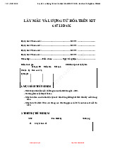
Lấy Mẫu và Lượng Tử Hóa Tín Hiệu Trên Kit C6713 DSK - Báo Cáo Thí Nghiệm môn Xử lý tín hiệu số| Đại học Bách khoa Hà Nội
45 23 -
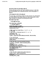
Mô phỏng hàm truyền trong Python: Hướng dẫn sử dụng scipy.signal và control môn Xử lý tín hiệu số| Đại học Bách khoa Hà Nội
45 23 -
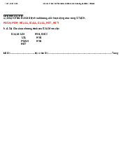
VXL HK231 DE1 DA Final Exam Solutions and Code Explanations môn Xử lý tín hiệu số| Đại học Bách khoa Hà Nội
47 24 -
A Model for Mobile Content Filtering in Recommendation Systems môn Xử lý tín hiệu số| Đại học Bách khoa Hà Nội
49 25