Electrical Wiring Diagrams - Hệ Thống Điện Động cơ và ô tô | Đại học Sư phạm Kỹ thuật Vĩnh Long
This wiring diagram manual has been prepared to provideinformation on the electrical system of the 1990 TOYOTACAMRY. Tài liệu giúp bạn tham khảo, ôn tập và đạt kết quả cao. Mời bạn đọc đón xem!
Môn: Hệ thống điện động cơ và ô tô 19 tài liệu
Trường: Trường Đại học Sư phạm Kỹ thuật Vĩnh Long 63 tài liệu
Tác giả:


Preview text:
FOREWORD
This wiring diagram manual has been prepared to provide
information on the electrical system of the 1990 TOYOTA CAMRY. Applicable models: SV21, 25 series VZV21 series
For service specifications and repair procedures of the above
models other than those listed in this manual, refer to the following manuals; Manual Name Pub. No. 1990 Camry Repair Manual Volume 1 RM151U1 Volume 2 RM151U2
TCCS (3S–FE) Diagnosis Manual DM011U
ECT (A140E) Diagnosis Manual DM013U
ECT (A540E) Diagnosis Manual DM014U NCF059U
1990 Model New Car Features
All information in this manual is based on the latest product
information at the time of publication. However, specifications
and procedures are subject to change without notice. T OYOTA M O TOR CORPORATION INTRODUCTION
This manual consists of the following 12 sections: No. Section Description 1 INDEX
Index of the contents of this manual. 2 INTRODUCTION
Brief explanation of each section. 3 HOW TO USE THIS MANUAL
Instructions on how to use this manual. 4 TROUBLE– SHOOTING
Describes the basic inspection procedures for electrical circuits. 5 ABBREVIATIONS
Defines the abbreviations used in this manual. GLOSSAR Y OF 6 TERMS AND
Defines the symbols and functions of major parts. SYMBOLS 7 RELAY LOCATIONS
Shows position of the Electronic Control Unit, Computer, Relays, Junction
Block, etc. This section is closely related to the system circuit. 8 ELECTRICAL
Describes position of the Parts Connectors, Ground points, etc. WIRE ROUTING
This section is closely related to the system circuit. POWER SOURCE 9 (POWER–LOAD,
Describes power distribution from the power supply to various electrical Reference) loads. 10 INDEX Index of the system circuits.
Electrical circuits of each system are shown from the power supply through
ground points. Wiring connections and their positions are shown and
classified by code according to the connection method. (Refer to the SYSTEM CIRCUITS
section, “How to use this manual”). 11
The “System Outline” and “Service Hints” useful for troubleshooting are
also contained in this section. GROUND POINTS
Shows ground positions of all parts described in this manual. 12 OVERALL WIRING DIAGRAM
Provides circuit diagrams showing the circuit connections. 2 HOW TO USE THIS MANUAL
This manual provides information on the electrical circuits installed on vehicles by
dividing them into each system circuit.
The actual wiring of each system circuit is shown from the point where the power source
is received from the battery as far as each ground point. (Al circuit diagrams are shown
with the switches in the OFF position.)
When troubleshooting any problem, first understand the operation of the circuit where
the problem was detected (see System Circuit section), the power source supplying
power to that circuit (see Power Source section), and the ground points (see Ground
Points section). See the System Outline to understand the circuit operation.
When the circuit operation is understood, begin troubleshooting of the problem circuit
to isolate the cause. Use Relay Location and Electrical Wire Routing sections to find
each part, junction block and wiring harness connectors, wiring harness and wiring
harness connectors, and ground points of each system circuit. Internal wiring for each
junction block is also provided for better understanding of connection within a junction block.
Wiring related to each system is indicated in each system circuit by arrows (from
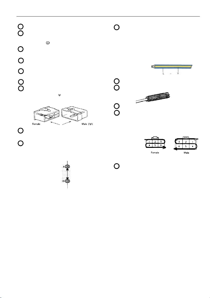
, to ) . When o verall connections are required, see the O verall Wiring D iagra at the end of this manual. 3 HOW TO USE THIS MANUAL 4 A : System T itle J : Indicates the wiring color. B
: Indicates a Relay Block. No shading is used and only
Wire colors are indicated by an alphabetical code.
the Relay Block No. is shown to distinguish it from the J/B. B = Black L = Blue R = Red Example: Indicates Relay Block No. 1. BR = Brown LG = Light Green V = Violet C
: Indicates the connector to be connected to a part (the G = Green O = Orange W = White numeral indicates the pin No.) GR = Gray P = Pink Y = Yellow
The first letter indicates the basic wire color and the D : Connector Color
second letter indicates the color of the stripe.
Connectors not indicated are milky white in color. Example: L – Y E : (
) is used to indicate dif ferent wiring and connector,
etc. when the vehicle model, engine type, or specification is di fferent. (Blue) (Yellow) F K : Indicates related system. : Page No. G L
: Indicates the wiring harness and wiring harness
: Indicates a sealed wiring harness.
connector. The wiring harness with male terminal is shown with arrows ( ).
Outside numerals are pin numbers. M : Indicates a ground point. N
: Indicates the pin number of the connector.
The numbering system is dif erent for female and male connectors. Example: Numbered in order Numbered in order H
: Represents a part (al parts are shown in sky blue). The from upper left to from upper right to
code (e.g. ) is the same as the code used in parts lower right lower left position. I
: Junction Block (The number in the circle is the J/B No.
and the connector code is shown beside it). Junction
Blocks are shaded to clearly separate them from other
parts (dif ferent junction blocks are shaded dif ferently for further clarification).
The numbering system for the overal wiring diagram i s Example: the same as above. O 3B indicates
: When 2 parts both use one connector in common, the that it is inside
parts connector name used in the wire routing section Junction Block is shown in square brackets [ ]. No. 3. 5 HOW TO USE THIS MANUAL P SYSTEM OUTLINE
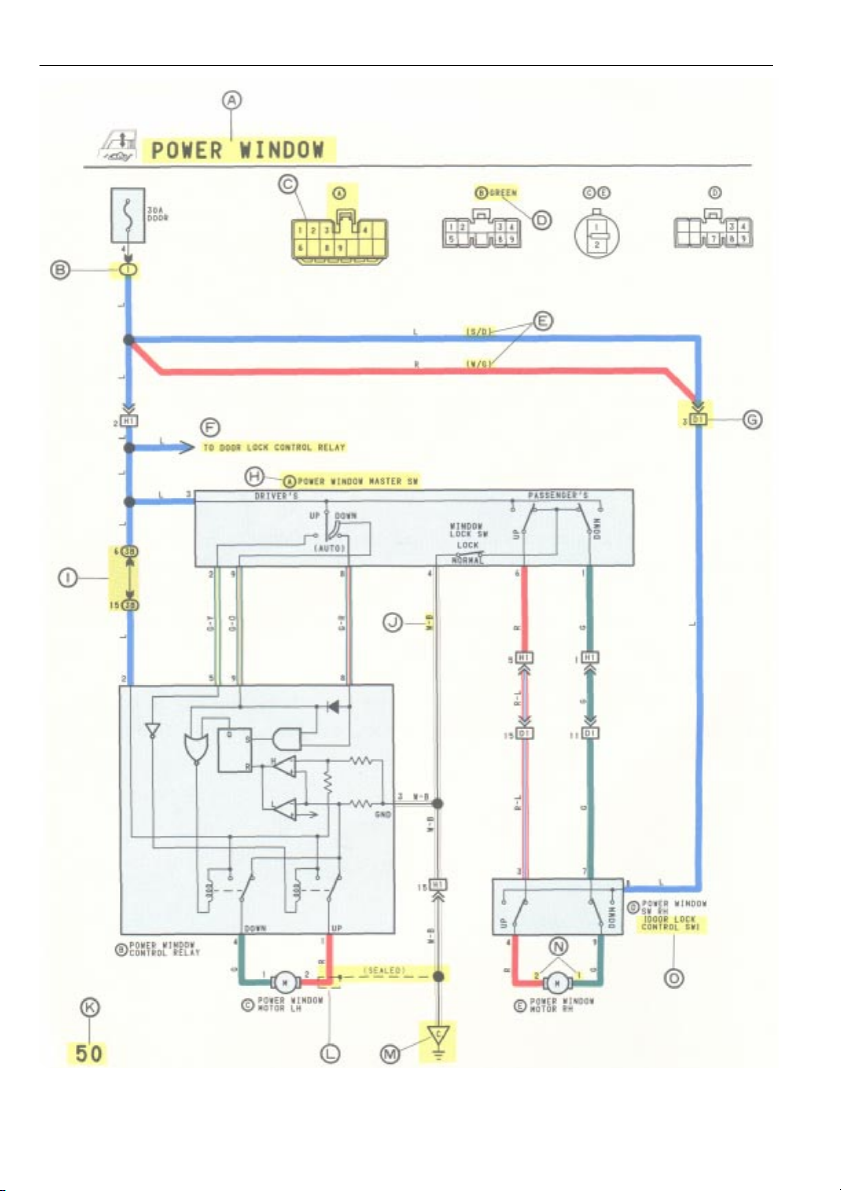
WITH THE IGNITION SW TURNED ON, THE CURRENT FLOWS TO TERMINAL 3 OF THE POWER WINDOW MASTER SW, TERMINAL 2 OF THE POWER WINDOW CONTROL RELAY
AND TERMINAL 8 OF THE POWER WINDOW SW THROUGH THE DOOR FUSE. 1.
DRIVER’S WINDOW “MANUAL UP” OPERATION BY MASTER SW
HOLDING MANUAL SW (DRIVER’S) ON “UP” POSITION LOCATED IN POWER WINDOW MASTER SW, THE CURRENT FLOWS TO TERMINAL 5 OF THE POWER WINDOW
CONTROL RELAY THROUGH TERMINAL 3 OF THE MASTER SW TERMINAL 2 T O OPERATE A POWER WINDOW CONTROL RELAY. THUS THE CURRENT INSIDE THE RELAY
FLOWS FROM TERMINAL 2 OF THE RELAY TERMINAL 1 TERMINAL 2 O F THE POWER WINDOW MOTOR TERMINAL 1 TERMINAL 4 OF THE RELAY TERMINAL
3 TO GROUND. THE MOTOR TURNS TO RAISE THE WINDOW. RELEASING THIS SW, THE ROTA T ION OF MOTOR IS STOPPED AND THE WINDOWS STOP AT DESIRED POINT.
(FOR THE “MANUAL DOWN” OPERATION, CURRENT FLOWS IN THE REVERSE DIRECTION BECAUSE THE TERMINALS WHERE IT FLOWS ARE CHANGED). 2.
DRIVER’S WINDOW “AUTO DOWN” OPERATION BY MASTER SW
ONCE THE “AUTO DOWN” BUTTON OF THE MASTER SW IS PUSHED, THE CURRENT FLOWS TERMINAL 9 OF THE POWER WINDOW CONTROL RELAY THROUGH TERMINAL
3 OF THE MASTER SW TERMINALS 8 AND 9 TO OPERATE THE RELAY. THUS THE CURRENT INSIDE THE POWER WINDOW CONTROL RELAY FLOWS FROM TERMINAL
2 OF THE RELAY TERMINAL 4 TERMINAL 1 OF THE POWER WINDOW MOTOR TERMINAL 2 TERMINAL 1 OF THE RELAY TERMINAL 3 TO GROUND.
THE MOTOR CONTINUES TO ROTATE, ENABLING THEWINDOW TO DESCEND.
WHEN THE WINDOW DESCENDS TO THE END POSITION, THE CURRENT IS CUT OFF TO RELEASE THE AUTO DOWN FUNCTION BASED ON THE INCREASING CURRENT
BETWEEN TERMINAL 2 OF THE RELAY AND TERMINAL 1 IN RELAY. 3.
DRIVER’S WINDOW AUTO DOWN RELEASE OPERATION BY MASTER SW
BY HOLDING THE MANUAL SW (DRIVER’S) IN “UP” POSITION WHILE OPERATING AUTO DOWN. THE CURRENT FROM TERMINAL 3 OF THE MASTER SW PASSING THROUGH
TERMINAL 2 FLOWS TO TERMINAL 5 OF THE RELAY AND RELEASES THE AUTO DOWN FUNCTION IN THE POWER WINDOW CONTROL RELAY. RELEASING THE HAND FROM
SW, STOPS THE WINDOW AND CONTINUING TO TOUCH THE SW, SWITCHES THE FUNCTION TO MANUAL UP OPERATION. 4.
PASSENGER’S WINDOW UP OPERATION (MASTER SW) AND WINDOW LOCK SW OPERATION
HOLDING PASSENGER’S WINDOW SW (MASTER SW) ON “UP”, THE CURRENT FLOWS FROM TERMINAL 3 OF THE MASTER SW THROUGH TERMINAL 6 TO TERMINAL 3 OF
THE POWER WINDOW SW (PASSENGER’S) TERMINAL 4 TERMINAL 2 O F THE MOTOR TERMINAL 1 TERMINAL 9 OF THE POWER WINDOW SW TERMINAL
7 TERMINAL 1 OF THE MASTER SW TERMINAL 4 TO GROUND. THE MOTOR RUNS TO RAISE THE WINDOW. RELEASING THIS SW, THE ROTATION OF MOTOR IS
STOPPED AND WINDOW STOPS AT THE DESIRED POINT.
SWITCHING THE WINDOW LOCK SW IN “LOCK” POSITION, THE CIRCUIT IS OPENED AND STOPS THE MOTOR ROTATION.
(FOR THE DOWN OPERATION, CURRENT FLOWS IN THE REVERSE DIRECTION BECAUSE THE TERMINALS WHERE IT FLOWS ARE CHANGED). 5.
PASSENGER’S WINDOW DOWN OPERATION (POWER WINDOW SW)
HOLDING POWER WINDOW SW ON “DOWN”, THE CURRENT FLOWS FROM TERMINAL 8 OF THE POWER WINDOW SW TERMINAL 9 TERMINAL 1 OF THE MOTOR
TERMINAL 2 TERMINAL 4 OF THE POWER WINDOW SW TERMINAL 3 TERMINAL 6 OF THE MASTER SW TERMINAL 4 TO GROUND. THE MOTOR RUNS TO LOWER THE WINDOW.
(FOR THE UP OPERATION, CURRENT FLOWS IN THE REVERSE DIRECTION BECAUSE THE TERMINALS WHERE IT FLOWS ARE CHANGED). Q SERVICE HINTS (A) POWER WINDOW MASTER SW 4–GROUND: ALWAYS CONTINUITY
3–GROUND: APPROX. 12 VOLTS WITH IGNITION SW AT ON POSITION (B) POWER WINDOW CONTROL RELAY 3–GROUND: ALWAYS CONTINUITY
2–GROUND: APPROX. 12 VOLTS WITH IGNITION SW AT ON POSITION
5–GROUND: APPROX. 12 VOLTS WITH IGNITION SW AT ON POSITION AND MASTER SW AT UP POSITION
8–GROUND: APPROX. 12 VOLTS WITH IGNITION SW AT ON POSITION AND MASTER SW AT AUTO DOWN POSITION
9–GROUND: APPROX. 12 VOLTS WITH IGNITION SW AT ON POSITION AND MASTER SW AT DOWN OR AUTO DOWN POSITION WINDOW LOCK SW
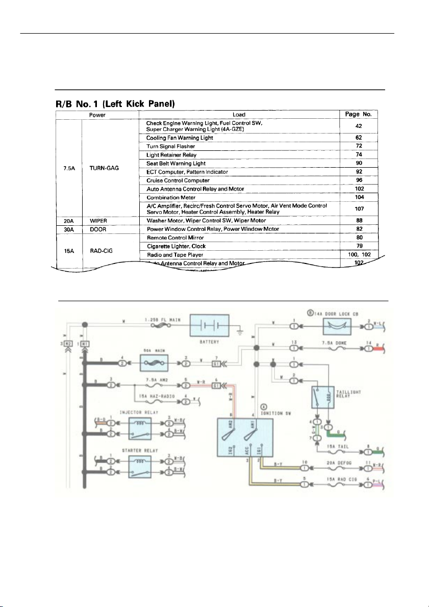
OPEN WITH WINDOW LOCK SW AT LOCK POSITION R : PARTS LOCATION CODE SEE PAGE CODE SEE PAGE CODE SEE PAGE A P4 21 C P5 21 E P6 21 B P2 21 D P3 21 S : RELAY BLOCKS CODE SEE PAGE
RELAY BLOCK (RELAY BLOCK LOCATION) 1 16
R/B NO. 1 (INSTRUMENT PANEL LEFT) T
: JUNCTION BLOCK AND WIRE HARNESS CONNECTOR CODE SEE PAGE
JUNCTION BLOCK AND WIRE HARNESS (CONNECTOR LOCATION) 3B 14
J/B NO. 3 AND COWL WIRE (INSTRUMENT PANEL LEFT SIDE) U
: CONNECTOR JOINING WIRE HARNESS AND WIRE HARNESS CODE SEE PAGE
JOINING WIRE HARNESS AND WIRE HARNESS (CONNECTOR LOCATION) D1 26
FRONT DOOR RH WIRE AND COWL WIRE (RIGHT KICK PANEL) H1 26
FRONT DOOR LH WIRE AND COWL WIRE (LEFT KICK PANEL) V : GROUND POINTS CODE SEE PAGE GROUND POINT LOCATION C 24 COWL LEFT 6
P : Explains the system outline.
Q : Indicates values or explains the function for reference during troubleshooting.
R : Indicates the reference page showing the position on the vehicle of the parts in the system circuit.
Example: Part A (Power Window Master SW) represents code P4 on page 21 of the manual.
* The letter in the code is from the first letter of the part, and the number indicates its order
in parts starting with that letter. Example: P 4 Part is 4th in order Power Window Master SW
S : Indicates the reference page showing the position on the vehicle of Relay Block Connectors in the system circuit.
Example: Connector 1 is described on page 16 of this manual and is installed on the left side of the instrument panel.
T : Indicates the reference page showing the position on the vehicle of J/B and Wire Harness in the system circuit.
Example: Connector 3B connects the Cowl Wire and J/B No. 3. It is described on page 14 of this
manual, and is installed on the instrument panel left side.
U : Indicates the reference page describing the wiring harness and wiring harness connector (the female
wiring harness is shown first, followed by the male wiring harness).
Example: Connector D1 connects the front door RH wire (female) and cowl wire (male). It is described
on page 26 of this manual, and is installed on the right side kick panel.
V : Indicates the reference page showing the position of the ground points on the vehicle.
Example: Ground point C is described on page 24 of this manual and is instal ed on the cowl left side. 7 HOW TO USE THIS MANUAL
The Power – Load section, describes which parts each power source (fuses, fusible links, and circuit breakers) transmits
current to. In the Power Source circuit diagram, the conditions when battery power is supplied to each system are explained.
Since all System Circuit diagrams start from the power source, the power source system must be fully understood.
POWER SOURCE (Power–Load, Reference) POWER SOURCE 8
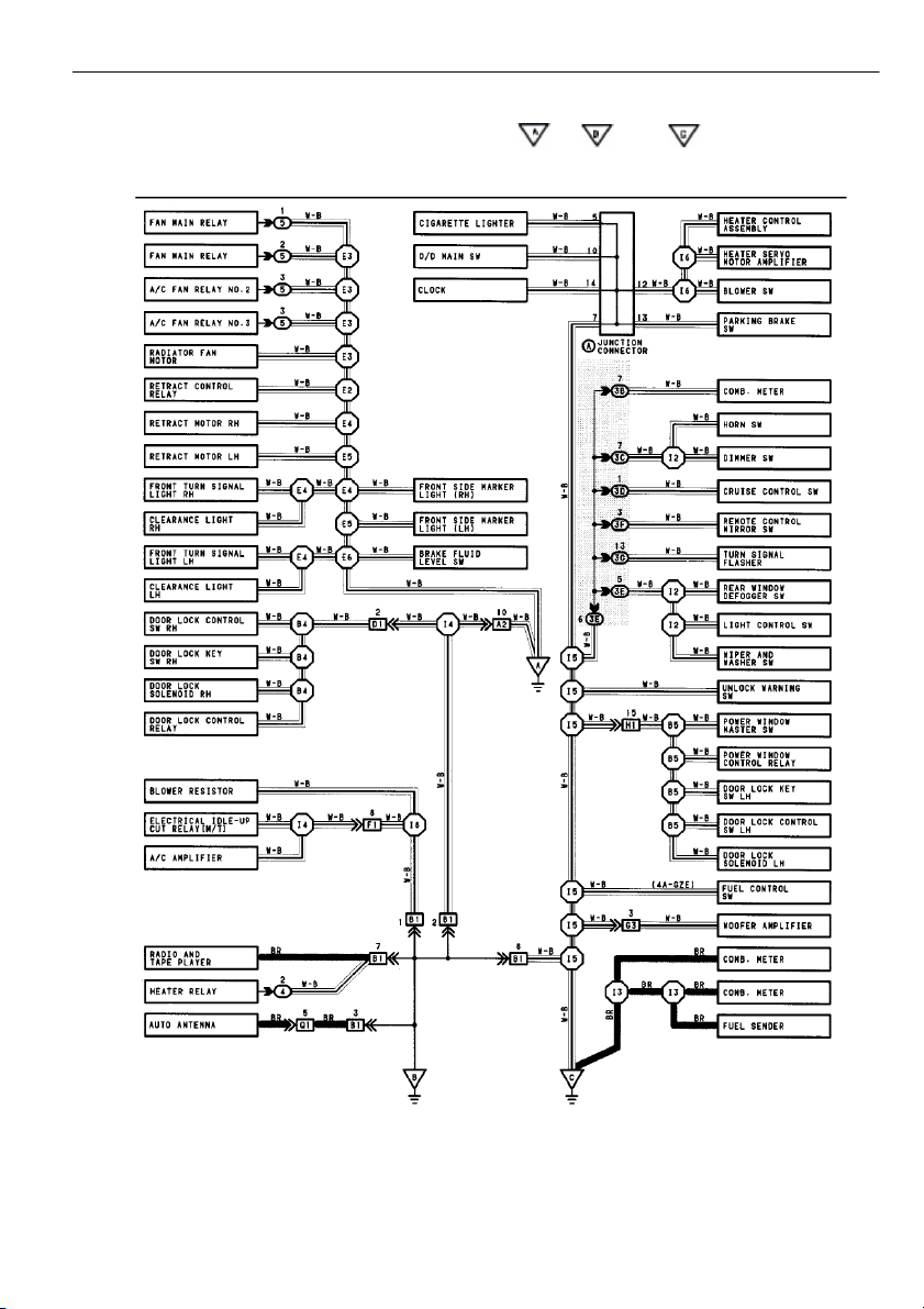
The ground points circuit diagram shows the connections from all major parts to the respective ground points. When
troubleshooting a faulty ground point, checking the system circuits which use a common ground may help you identify the
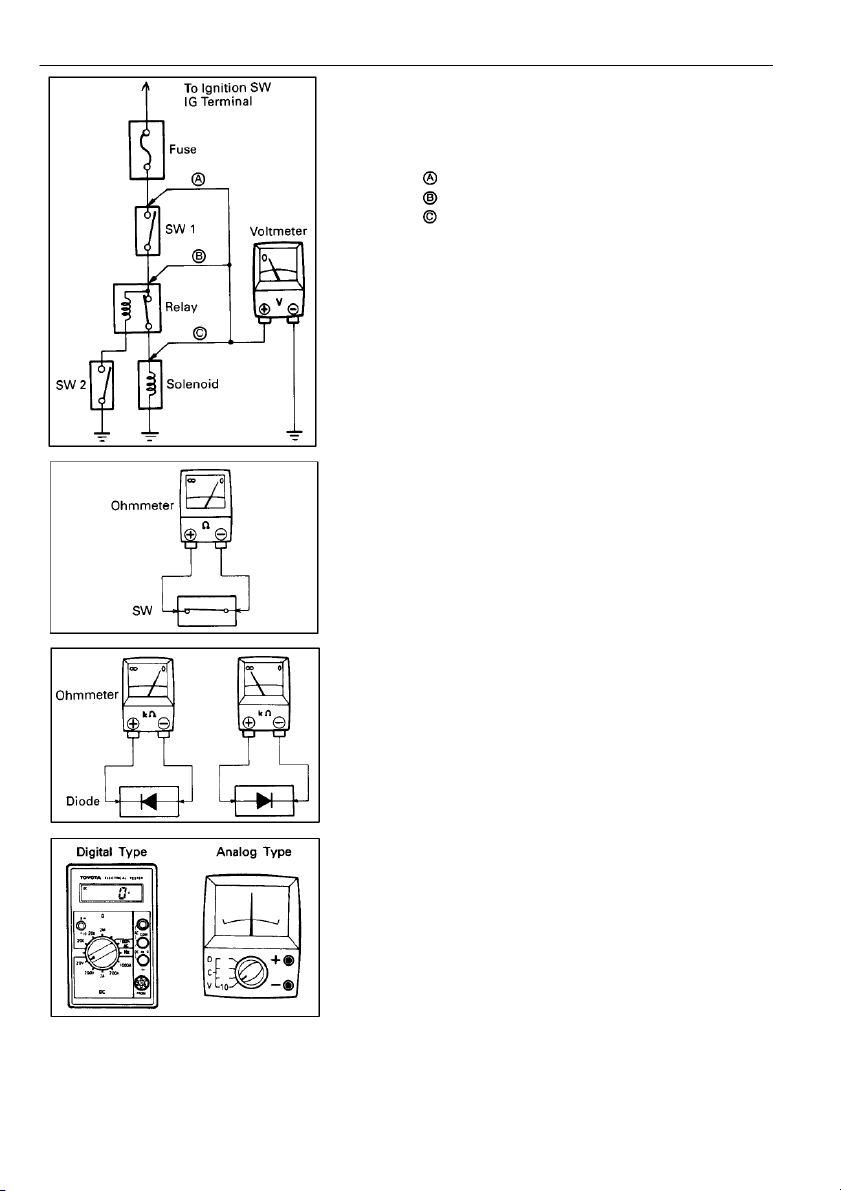
problem ground quickly. The relationship between ground points ( , , and shown below) can also be checked this way. GROUND POINTS 9 TROUBLESHOOTING VOLTAGE CHECK (a)
Establish conditions in which voltage is present at the check point. Example: – Ignition SW on – Ignition SW and SW 1 on
– Ignition SW, SW 1 and Relay on (SW 2 off) (b)
Using a voltmeter, connect the negative lead to a good
ground point or negative battery terminal, and the
positive lead to the connector or component terminal.
This check can be done with a test light instead of a voltmeter.
CONTINUITY AND RESISTANCE CHECK (a)
Disconnect the battery terminal or wire so there is no
voltage between the check points. (b)
Contact the two leads of an ohmmeter to each of the check points.
If the circuit has diodes, reverse the two leads and check again.
When contacting the negative lead to the diode positive side
and the positive lead to the negative side, there should be continuity.
When contacting the two leads in reverse, there should be no continuity. (c)
Use a volt/ohmmeter with high impedance (10 kΩ/V
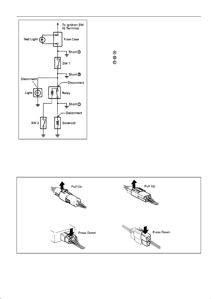
minimum) for troubleshooting of the electrical circuit. 10 FINDING A SHORT CIRCUIT (a)
Remove the blown fuse and disconnect al loads of the fuse. (b)
Connect a test light in place of the fuse. (c)
Establish conditions in which the test light comes on. Example: – Ignition SW on – Ignition SW and SW 1 on
– Ignition SW, SW 1 and Relay on (Connect the
Relay) and SW 2 off (or Disconnect SW 2) (d)
Disconnect and reconnect the connectors while watching the test light.
The short lies between the connector where the test
light stays lit and the connector where the light goes out. (e)
Find the exact location of the short by lightly shaking
the problem wire along the body. CAUTION:
Do not open the cover or the case of the ECU and
various computer unless absolutely necessary. (If the
IC terminals are touched, the IC may be destroyed by static electricity.)
DISCONNECTION OF MALE AND FEMALE CONNECTORS
To pull apart the connectors, pull on the connector itself, not the wire harness.
HINT: Check to see what kind of connector you are disconnecting before pulling apart. 11 TROUBLESHOOTING
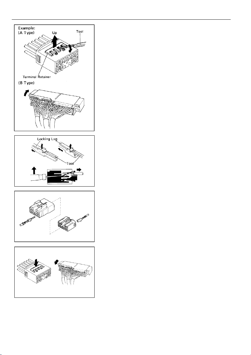
HOW TO REPLACEMENT FOR TERMINAL (with Terminal Retainer Type) 1. DISCONNECT CONNECTOR 2.
DISCONNECT TERMINAL FROM CONNECTOR (a) “for A type”
Raise the terminal retainer up to the temporally lock position.
HINT: The needle insertion position varies according
to the connector’s shape (number of terminals
etc.), so check the position before inserting it. “for B type” Open the terminal retainer. (b)
Release the locking lug from terminal and pull the terminal out from rear. 3. INSTALL TERMINAL TO CONNECTOR (a) Insert the terminal. HINT: 1.
Make sure the terminal is positioned correctly. 2.
Insert the terminal until the locking lug locks firmly. 3.
Insert the terminal with terminal retainer in the temporally lock position. (b)
Push the terminal retainer in to the full lock position. 4. CONNECT CONNECTOR 12 ABBREVIATIONS ABBREVIATIONS
The following abbreviations are used in this manual. A/C = Air Conditioner A.B.S = Anti Lock Brake System A/T = Automatic Transmission CB = Circuit Breaker COMB. = Combination DIFF. = Differential ECT
= Electronic Controlled Transmission ECU = Electronic Control Unit EFI = Electronic Fuel Injection EGR = Exhaust Gas Recirculation EX. = Except FL = Fusible Link ISC = Idle Speed Control J/B = Junction Block LH = Left-Hand M/T = Manual Transmission O/D = Overdrive R/B = Relay Block RH = Right–Hand SW = Switch TCCS
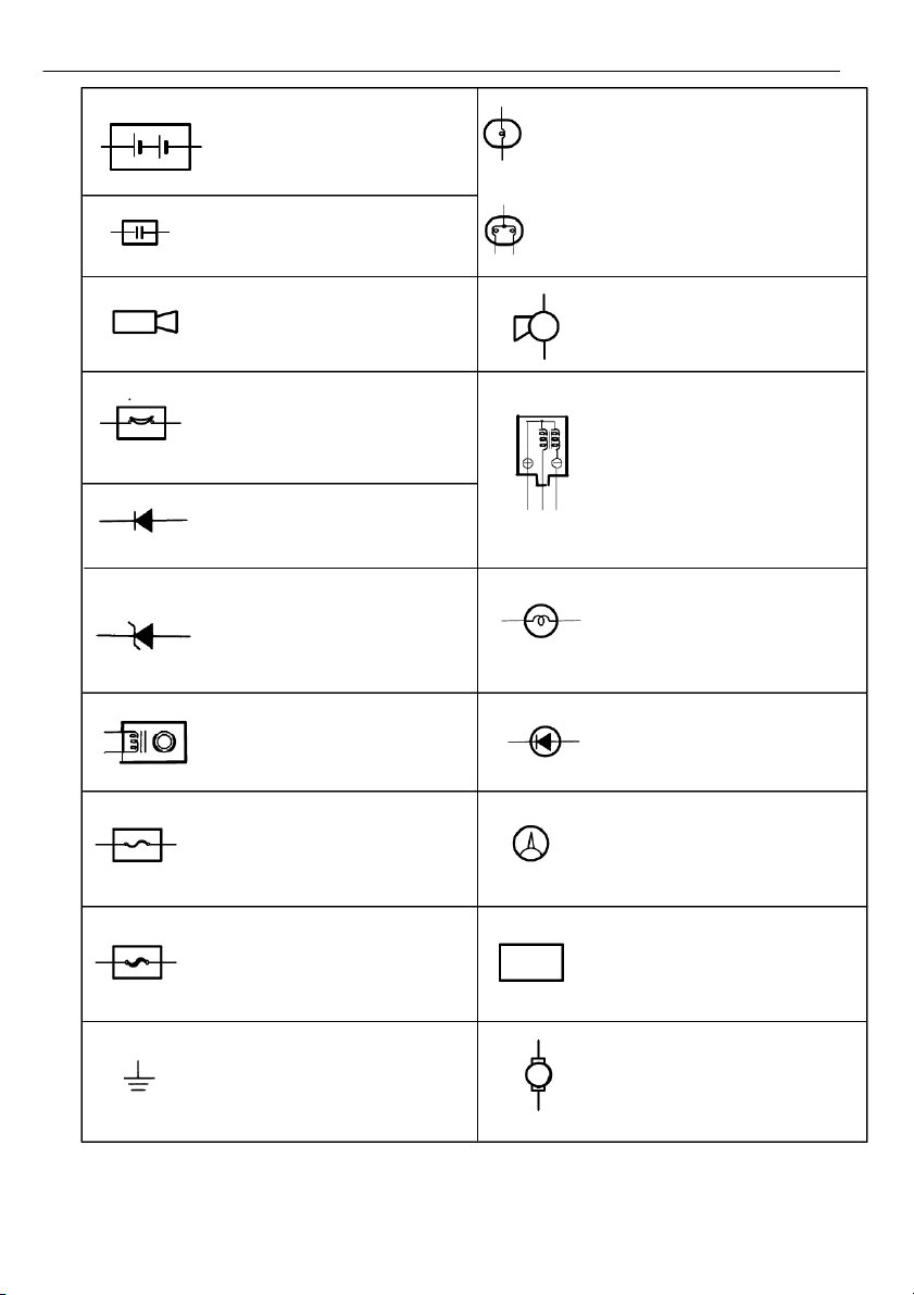
= Toyota Computer Controlled System TEMP. = Temperature VSV = Vacuum Switching Valve W/G = Wagon Type W/ = With W/O = Without 4WD = Four Wheel Drive 13 GLOSSARY OF TERMS AND SYMBOLS BATTERY
HEADLIGHTS Current flow causes a headlight Stores chemical energy and
filament to heat up and emit light. 1. SINGLE
converts it into electrical energy. A headlight may have either a
Provides DC current for the auto’s
FILAMENT single (1) filament or a double (2) various electrical circuits. filament. CAPACITOR (Condenser) 2. DOUBLE
A small holding unit for temporary FILAMENT storage of electrical voltage. CIGARETTE LIGHTER HORN An electric resistance heating
An electric device which sounds a element. loud audible signal. CIRCUIT BREAKER
Basically a reusable fuse, a circuit
breaker will heat and open if too IGNITION COIL
much current flows through it. Some
units automatically reset when cool,
Converts low–voltage DC current others must be manually reset.
into high–voltage ignition current for firing the spark plugs. DIODE A semiconductor which allows
current flow in only one direction. DIODE, ZENER LIGHT
A diode which allows current flow
Current flow through a filament
in one direction but blocks reverse causes the filament to heat up
flow only up to a specific voltage. and emit light.
Above that potential, it passes the excess voltage. This acts as a simple voltage regulator. DISTRIBUTOR, IIA LED (LIGHT EMITTING DIODE)
Channels high–voltage current
Upon current flow, these diodes from the ignition coil to the
emit light without producing the individual spark plugs. heat of a comparable light. FUSE METER, ANALOG A thin metal strip which burns
Current flow activates a magnetic through when too much current coil which causes a needle to
flows through it, thereby stopping
move, thereby providing a relative current flow and protecting a display against a background circuit from damage. calibration. FUSIBLE LINK METER, DIGITAL A heavy–gauge wire placed in Current flow activates one or high amperage circuits which
many LED’s, LCD’s, or flourescent FUEL burns through on overloads,
displays, which provide a relative
thereby protecting the circuit. or digital display. GROUND MOTOR
The point at which wiring attaches A power unit which converts
to the Body, thereby providing a M
electrical energy into mechanical
return path for an electrical circuit;
energy, especially rotary motion.
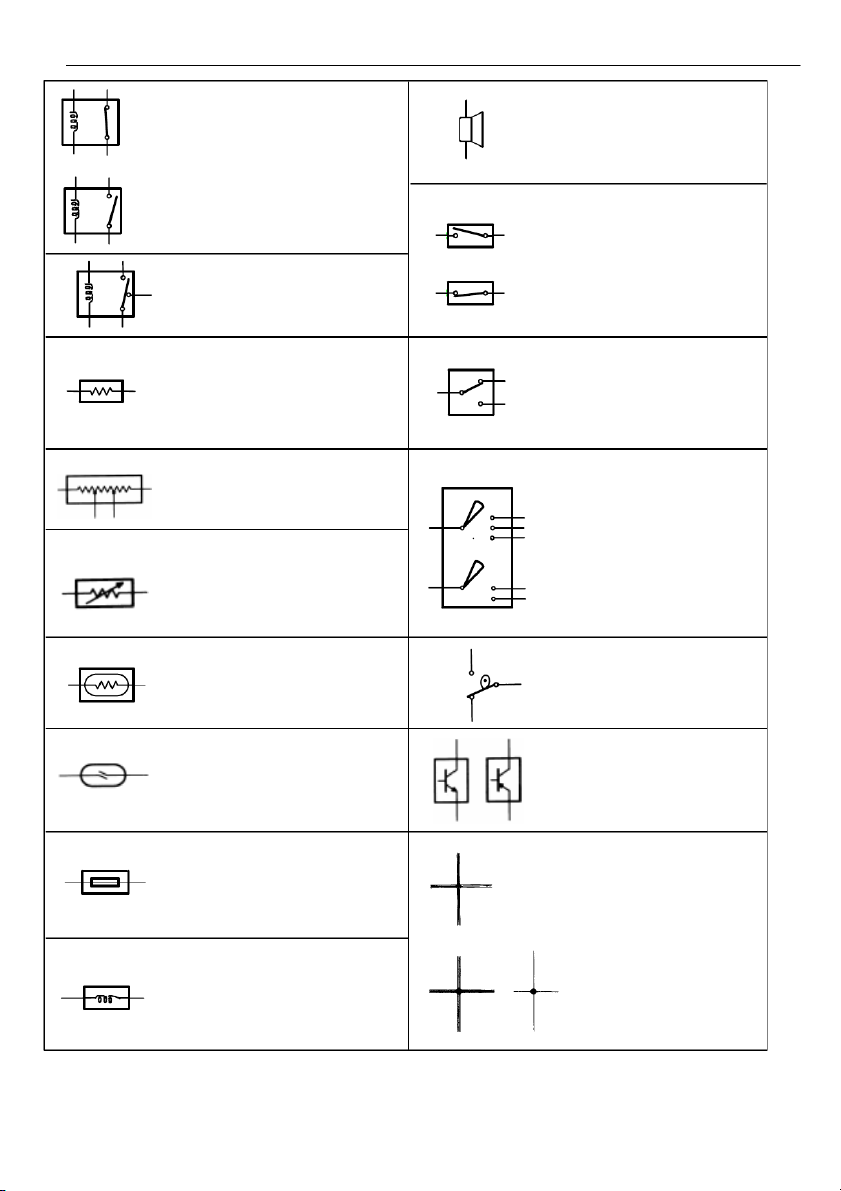
without a ground, current cannot flow. 14 RELAY Basically, an electrically SPEAKER operated switch which may An electromechanical device
1. NORMALLY be normally closed (1) or which creates sound waves from CLOSED open (2). current flow. Current flow through a small coil creates a 2. NORMALLY magnetic field which either SWITCH, MANUAL OPEN opens or closes an attached switch. Opens and 1. NORMALLY closes circuits, OPEN thereby stopping (1) or RELAY, DOUBLE THROW al owing (2) A relay which passes current 2. NORMALLY current flow.
through one set of contacts or the CLOSED other. RESISTOR SWITCH, DOUBLE THROW An electrical component with a A switch which continuously
fixed resistance, placed in a circuit passes current through one set
to reduce voltage to a specific of contacts or the other. value. RESISTOR, TAPPED SWITCH,
A resistor which supplies two or IGNITION
more different non–adjustable A key operated switch with resistance values. several positions which al ow
various circuits. Particularly the primary ignition circuit, to RESISTOR, VARIABLE or become operational. RHEOSTAT A controllable resistor with a variable rate of resistance. Also called a potentiometer or rheostat. SENSOR (Thermistor) SWITCH, WIPER PARK A resistor which varies its
Automatically returns wipers to resistance with temperature.
the stop position when the wiper switch is turned off. SENSOR, ANALOG SPEED TRANSISTOR Uses magnetic impulses to open
A solidstate device typically used and close a switch to create a
as an electronic relay; stops or signal for activation of other
passes current depending on the components. applied voltage at “base.” SHORT PIN WIRES Wires are always Used to provide an unbroken drawn as straight (1) NOT
connection within a junction block. CONNECTED lines on wiring diagrams. Crossed wires (1) without a black dot at the (2) SPLICED junction are not SOLENOID joined; An electromagnetic coil which crossed wires (2) forms a magnetic field when with a black dot at
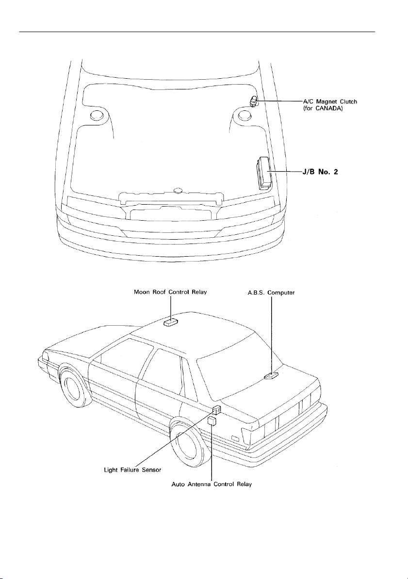
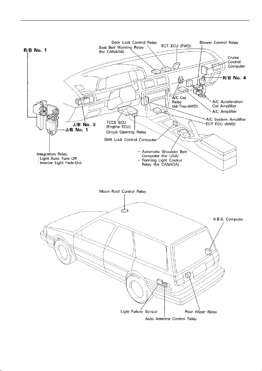
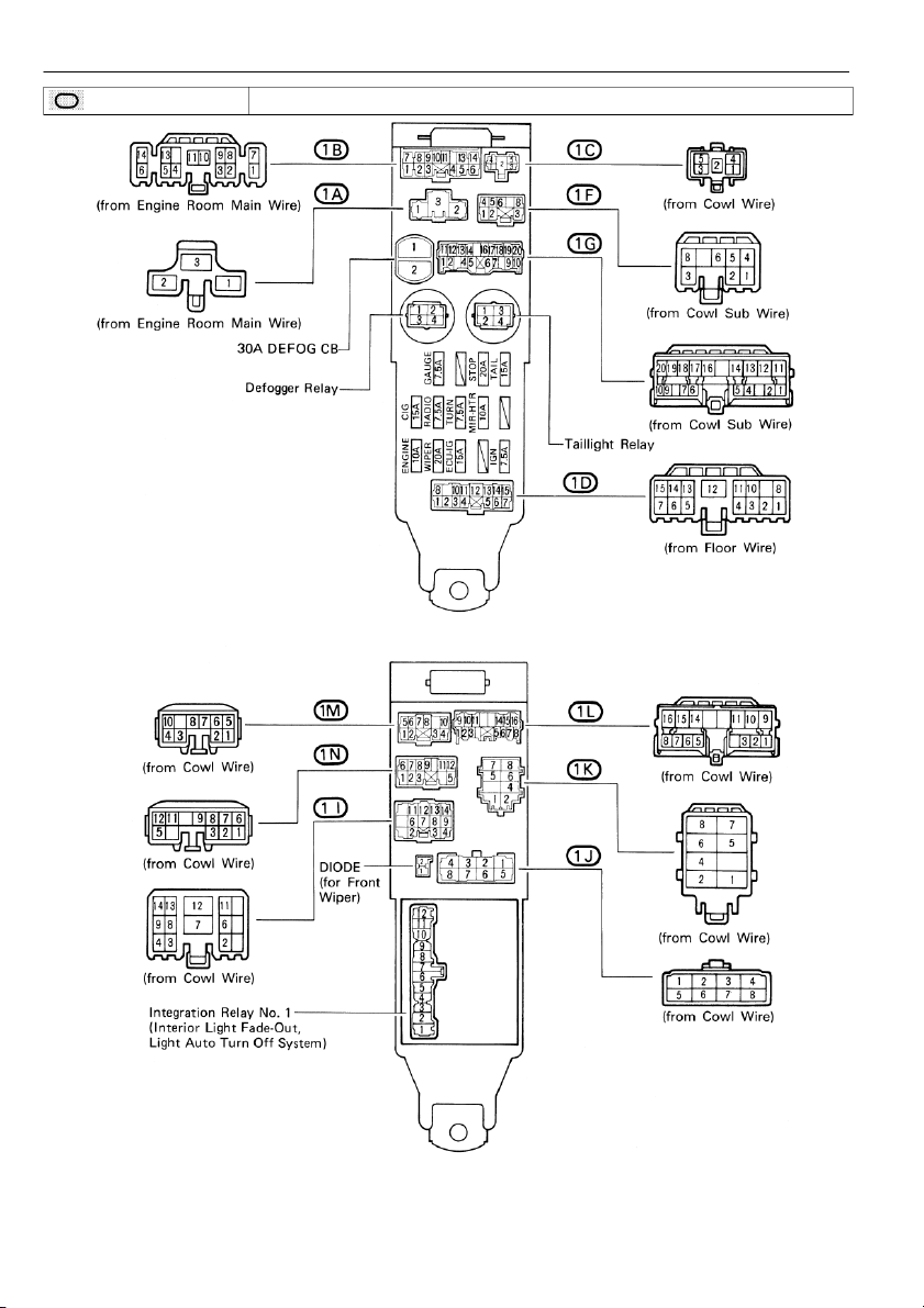
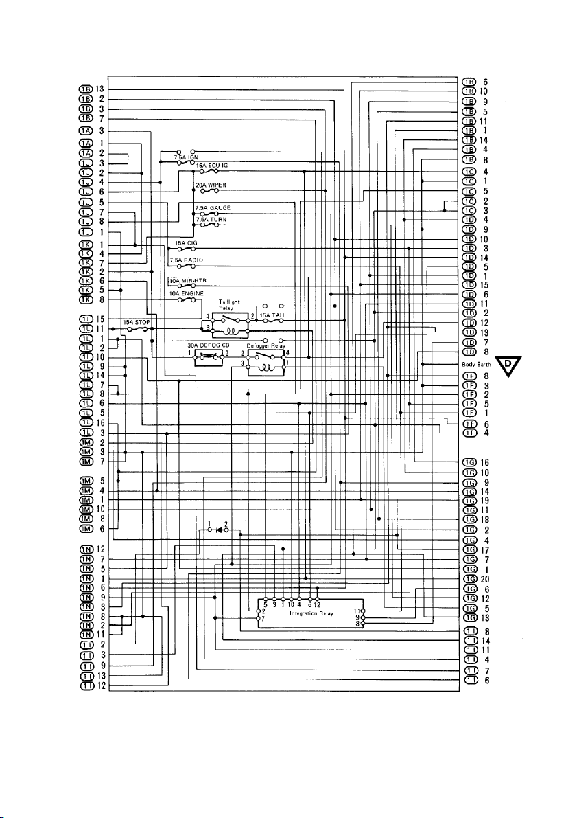
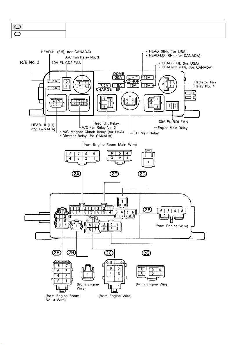
current flows, to move a plunger, the junction are etc. spliced (joined) connections. 15 RELAY LOCATIONS [Engine Compartment] [Body] [S/D] 16 [Instrument Panel] [Body] [WAGON] 17 RELAY LOCATIONS ,,, : J/B No. 1 Left Kick Panel (See Page 17) ,, , 18 [J/B No. 1 Inner Circuit] 19 RELAY LOCATIONS ,,, : J/B No. 2 ,, , En E g n i g ne n Compartm t e m n e t n t L e L f etft (S ( e S e e Page 11 66 ) ) 2 : R/B No. 2 20
Tài liệu liên quan:
-
Đề Cương Điều Khiển Động Cơ - Hệ Thống Điện Động cơ và ô tô | Đại học Sư phạm Kỹ thuật Vĩnh Long
300 150 -
Nguyên lý máy đề - Hệ Thống Điện Động cơ và ô tô | Đại học Sư phạm Kỹ thuật Vĩnh Long
272 136 -
Tiểu luận nghiên cứu Xe chuyên dùng - Hệ Thống Điện Động cơ và ô tô | Đại học Sư phạm Kỹ thuật Vĩnh Long
882 441 -
Engine Vietnamese - Hệ Thống Điện Động cơ và ô tô | Đại học Sư phạm Kỹ thuật Vĩnh Long
230 115 -
Bài tập thuỷ lực và khí nén - Hệ Thống Điện Động cơ và ô tô | Đại học Sư phạm Kỹ thuật Vĩnh Long
431 216