Giáo trình Thiết kế và triển khai sản xuất theo mô hình tế bào trong môi trường xưởng gia công môn Quản trị sản xuất và tác nghiệp | Học viện Nông nghiệp Việt Nam
Giáo trình Thiết kế và triển khai sản xuất theo mô hình tế bào trong môi trường xưởng gia công môn Quản trị sản xuất và tác nghiệp | Học viện Nông nghiệp Việt Nam. Tài liệu được sưu tầm giúp bạn tham khảo, ôn tập và đạt kết quả cao. Mời bạn đọc đón xem.
Môn: Quản trị sản xuất và tác nghiệp 44 tài liệu
Trường: Học viện Nông nghiệp Việt Nam 2.5 K tài liệu
Tác giả:


Preview text:
DESIGN AND IMPLEMENTATION OF CELLULAR MANUFACTURING
IN A JOB SHOP ENVIRONMENT by
Liana María Alvarez López
B.S., Naval Architecture and Marine Engineering, Massachusetts Institute of Technology, 1987
M.S., Naval Architecture and Marine Engineering, Massachusetts Institute of Technology, 1993
Submitted to the Sloan School of Management and the
Department of Mechanical Engineering
in Partial Fulfillment of the Requirements for the Degrees of
Master of Business Administration and
Master of Science in Mechanical Engineering in Conjunction with the
Leaders for Manufacturing Program at the
Massachusetts Institute of Technology May 1997
1997 Massachusetts Institute of Technology Signature of Author Sloan School of Management
Department of Mechanical Engineering May 23, 1997 Certified by
Professor Eugene E. Covert, Thesis Advisor
Department of Aeronautics and Astronautics Certified by
Professor Stephen C. Graves, Thesis Advisor Sloan School of Management Accepted by
Professor Ain Sonin, Chairman, Graduate Committee
Department of Mechanical Engineering Certified by
Larry Abeln, Director of Master’s Program Sloan School of Management 2
Design and Implementation of Cellular Manufacturing
in a Job Shop Environment by
Liana María Alvarez López
Submitted to the Sloan School of Management and the
Department of Mechanical Engineering
in Partial Fulfillment of the Requirements for the Degrees of
Master of Business Administration and
Master of Science in Mechanical Engineering Abstract
The thesis proposes a method for introducing cellular manufacturing in an operating job shop. By
applying cellular manufacturing to produce part families with similar manufacturing processes and
stable demand, plants expect to reduce costs and lead-times and improve quality and delivery
performance. The thesis outlines a method for assessing, designing, and implementing cellular
manufacturing, and illustrates this process with an example. A manufacturing cell that produces
aluminum parts for commercial customers is implemented at Boeing’s Defense and Space Group
Machining Center. The conclusions of the thesis highlight the key lessons learned from this process. Thesis Advisors:
Professor Eugene E. Covert, Department of Aeronautics and Astronautics
Professor Stephen C. Graves, Sloan School of Management 3 4 Acknowledgments
The author gratefully acknowledges the support and resources made available to her through the
MIT Leaders For Manufacturing Program, a partnership between MIT and major U.S. manufacturing companies.
I would like to express my sincere thanks to Al Koszarek and all those at Boeing who helped and
encouraged me through my internship, and made the “cell” come true.
The author is also grateful to her thesis supervisors, Prof. Graves and Prof. Covert, for their
guidance through the internship and thesis process.
To my classmates and friends at MIT and away, thank you for being there for me, I could not
have done it without you. Last but certainly not least, I thank my parents, my sister and Michael
for their love and strength, the surest signs of God’s kindness. 5 6 Table of Contents
1. Introduction ......................................................................................................................... 11
1.1 Linking Boeing’s Defense and Space Group Business and Manufacturing Strategies............... 11
1.2 Background on the Machining Center ....................................................................................... 14
1.2.1 Customers .......................................................................................................................................... 16
1.2.2 Business Process Flow........................................................................................................................ 19
1.2.3 Capacity Planning Systems ................................................................................................................ 20
1.2.4 Metrics............................................................................................................................................... 23
1.2.5 Current Situation ............................................................................................................................... 24
1.3 Goal of Project ........................................................................................................................... 25
2. Assessment of Cellular Manufacturing................................................................................ 26
2.1 Product-Process Matrix ............................................................................................................. 26
2.2 Functional and Product Flow Layouts: Benefits and Limitations.............................................. 27
2.3 Cellular Manufacturing: Benefits and Limitations..................................................................... 29
2.4 Is There a Match? ...................................................................................................................... 30
2.5 Cell Design and Implementation Process ................................................................................... 31
3. Cell Planning Phase ............................................................................................................ 36
3.1 Assessment ................................................................................................................................. 36
3.2 Assessment at the Machining Center ......................................................................................... 38
3.2.1 Machining Center’s Current Situation................................................................................................ 39
3.2.2 Why a Cell at the Machining Center?................................................................................................. 40
3.3 Design ......................................................................................................................................... 41
3.3.1 Assemble Leadership Team................................................................................................................ 42
3.3.2 Identify Feasible Part Families ........................................................................................................... 43
3.3.3 Design Cell Process............................................................................................................................ 45
3.3.4 Launch the Performance Analysis ...................................................................................................... 46
3.3.5 Finalize Design Before Implementation.............................................................................................. 46
3.4 Design at the Machining Center ................................................................................................. 46 7
3.4.1 Cell Vision Team ............................................................................................................................... 47
3.4.2 Defining Part Families ....................................................................................................................... 48
3.4.3 Defining Cell Process......................................................................................................................... 51
3.5 Performance Analysis................................................................................................................. 53
3.5.1 Performance Analysis for Machining Center Cell............................................................................... 54
3.5.2 Finalizing the Design Phase ............................................................................................................... 56
4. Cell Implementation Phase .................................................................................................. 57
4.1 Implementation........................................................................................................................... 57
4.2 Accelerated Improvement Workshop at Machining Center ...................................................... 59
4.2.1 Cell Layout ........................................................................................................................................ 60
4.2.2 Set-Up Reduction ............................................................................................................................... 61
4.2.3 Inspection and Variability Reduction.................................................................................................. 62
4.2.4 Scheduling ......................................................................................................................................... 62
4.2.5 Total Productive Maintenance ............................................................................................................ 63
4.3 Performance Measurement ........................................................................................................ 63
4.3.1 Performance Measurement of the Machining Center Cell................................................................... 64
5. Conclusions.......................................................................................................................... 67 References 69 Appendix A 71 8 List of Figures
Figure 1.1 Machining Center Layout ........................................................................................ 15
Figure 1.2 Typical Part Process Flow ....................................................................................... 16
Figure 1.3 Current Work Breakdown by Customer in the Machining Center as Percentages of
Factory Direct Labor Hours............................................................................................... 17
Figure 1.4 Boeing Defense and Space Business Process Flow................................................... 19
Figure 2.1 The Product-Process Matrix .................................................................................... 27
Figure 2.2 Effect of Repeating the PDCA and CAPD Cycles .................................................... 33
Figure 2.3 Cell Design and Implementation Process.................................................................. 34
Figure 3.1 Part Family definition process in the Machining Center ............................................ 49
Figure 3.2 Primary Routing Sequences of Candidate Cell Part Family ....................................... 52
Figure 3.3 Cell Process............................................................................................................. 52
Figure 4.1 Cell Layout.............................................................................................................. 61
Figure 4.2 Average Variance to Standard for all Cell Machines for First Quarter of Operation .. 66 List of Tables
Table 1.1 Boeing Defense and Space Manufacturing Initiatives.................................................. 13
Table 1.2 Standard and Puget Sound Flow Times for a Fictitious Part ...................................... 22
Table 2.1 The PDCA and CAPD Cycles .................................................................................... 32
Table 3.1 Current Situation at Shop using a Sample of Commercial Parts ................................. 39
Table 3.2 Current Situation at Shop through its Own Metrics ................................................... 39
Table 3.3 Suggested Part Data for Cell Design Database .......................................................... 44
Table 3.4 Work Type Code Field Specifications ....................................................................... 48
Table 3.5 Result of Part Family Definition First Iteration .......................................................... 51
Table 3.6 Initial Required Capacity and Machine Availability Calculations ................................ 54
Table 3.7 Final Cell Capacity Calculations and Allocated Resources ......................................... 55 9 10 1. Introduction
The environment in which Boeing’s Defense and Space Group operates today is very different
from the one in which it has historically succeeded. The decline in defense spending has increased
the importance of cost or affordability in a decision process which previously emphasized the
incorporation of state-of-the-art technology into new military products. In addition, the defense
industry consolidation is producing fewer companies competing fiercely for a piece of a
decreasing pie. Therefore, Boeing’s Defense and Space Group (D&SG) success depends on its
ability to exceed customers’ expectations through superior performance, by delivering high quality
products in a timely manner, with shorter lead-times and lower costs.
This thesis explores whether or not cellular manufacturing can help D&SG’s Machining Center, a
highly flexible shop with many different customers and products, achieve improved performance and customer satisfaction.
The remainder of Chapter 1 discusses in more detail D&SG’s business and manufacturing
strategy, and it describes the Machining Center’s customers, business process and current
situation. The goal of the thesis is explained in more detail at the end of the chapter. Chapter 2
summarizes the advantages and disadvantages of functional layouts and cellular manufacturing. It
then explains why cellular manufacturing might benefit the Machining Center and its customers.
The chapter concludes with the five-step cell design process used to introduce cellular
manufacturing in the Center. Chapter 3 describes the first three steps in this cell design process,
corresponding to the planning phase. The analysis to determine the part families, cell process and
machines is presented, as well as the methods used to ensure cell performance. Chapter 4
discusses the implementation, immediate results and longer term expectations of the cell. Chapter
5 concludes by summarizing the key learnings and recommendations.
1.1 Linking Boeing’s Defense and Space Group Business and Manufacturing Strategies
Boeing’s Defense and Space Group has been one of the lead suppliers to the Department of
Defense and NASA. From the Minuteman missile to the Lunar Rover Vehicle, and more recently 11
the F-22 Fighter and NASA’s Space Station, D&SG has a solid and distinguished history of
innovation and technological edge in designing and building advanced products for the military
and space program.1 Even though most of D&SG traditional customers are cutting back on
spending, they continue to have real needs requiring the technical excellence that Boeing can
supply. In addition, there is an ongoing commercialization of many of the technologies that
historically have been pursued only by government concerns. For example, the opportunities in
space ventures are increasingly of a commercial nature given the growth in the
telecommunications industry. However, success not only depends on Boeing’s superior technical
expertise, but also in its ability to remain customer focused and competitive. This is why one of
the thrusts of D&SG’s business strategy is to become a preferred supplier for the Boeing
Commercial Airplane Group (BCAG). Support to BCAG is expected to help D&SG improve
competitiveness in its traditional and potential markets, as the same capabilities in the existing
product/service categories overlap between the military and commercial customers.
The D&SG Manufacturing mission statement incorporates the strategic intent of the group as a
whole: To be the supplier of choice to military and commercial customers in terms of quality,
profitability, and growth as measured by customer, employee and community satisfaction.2 To
that end, Manufacturing’s strategy focuses on customer satisfaction, growth and best practices.
Using best practices, Manufacturing can provide superior customer satisfaction at lower costs,
producing increased business from its existing customers and attracting new customers. An
interesting manifestation of this strategy is the way in which major functions and manufacturing
centers interact. While BCAG has created manufacturing business units at each of its
manufacturing centers by having functions report to the management of the business unit, D&SG
has maintained functions, operating at a Division level, and supporting the manufacturing centers
through representatives. By doing so, D&SG has created a matrix approach with the intent of not
only holding on to functional knowledge, but also eliminating the additional costs of duplicating
responsibilities or management within each manufacturing center.
1 Serling, R.J., Legend and Legacy The Story of Boeing and Its People, 1992, St. Martin’s Press, New York.
2 Boeing Defense and Space Group, Vision 2000, 1996 Operation Plan. 12
Table 1.1 Boeing Defense and Space Manufacturing Initiatives Initiative Thrust Variability Reduction
Involves implementing SPC at applicable key process
operations, and identifying process and products for
Manufacturing Self Examination (MSE). Total Productive Maintenance
Involves identifying critical machines and using preventive
maintenance and increased interaction between mechanics and
operators to maximize machine utilization. Manufacturing Centers
Involves collocating work groups/teams if 50% of their time is Nationwide
spent in a certain area. It also involves the close cooperation of
Manufacturing Centers, Functions and Integrated Product
Teams (IPT’s) to satisfy customer requirements. Increase Business Base
Involves achieving BCAG unit cost targets, delivering on time
to commitment date, and reducing overhead rate. Digital Driven Enterprise
Involves having machines and manufacturing processes driven
through digital engineering definition Rapid Prototyping Process
Involves integrating Rapid Prototyping Process in all
Manufacturing Centers and Operations Macro Process Initiatives. Macro Process Activity
Involves developing robust processes and proving them prior to
implementation particularly in the design/produce interface. State of the Art Business
Involves improving cost visibility throughout the D&S Group Systems
as well as preparing and implementing the new Boeing planning system DCAC/MRM. 50% Cycle Time reduction
Involves reducing cycle time by half every three years. from 1995 baseline Proactive Safety, Health and
Involves having processes and facilities incorporate highest Environmental (SHEA)
feasible level of safeguards for employee health and safety. It
also proposes a reduction of hazardous material use, and
attaining world-class standards in lost time due to accidents. Employee Satisfaction
Involves continual improvement of employee satisfaction as
measured by Employee Survey results using 1992 as baseline by
continuous improvement in communication, teamwork and assessment process. 5S Implementation
5S stands for Sorting, Simplifying, Sweeping, Standardizing, and Self-Discipline.
D&SG has launched many initiatives across all of its manufacturing centers. Table 1.1 offers a
summary of these initiatives and their thrust, which articulate the goals or measurable elements
defined as critical to become the dominant world-class supplier in the aerospace industry. All of
them represent important steps needed to bring about improvements in Manufacturing. However,
it is worth pointing out that sustaining focus and dedication to each initiative may be very difficult
as their number increases. There may be a danger of diluting employee attention by separating
efforts without prioritizing them. While all of the initiatives are important, some have a more 13
immediate operational focus, and others a more strategic nature. Given the company’s finite
financial and manpower resources, establishing time horizons, as well as identifying synergy’s
between initiatives could prove very useful. By doing so, projects that advance the goals of
several initiatives would be more easily identified and diligently pursued.
1.2 Background on the Machining Center
The Machining Center is one of the five D&SG Manufacturing Centers located in the Puget
Sound area. It produces structural details and/or assemblies for military and commercial
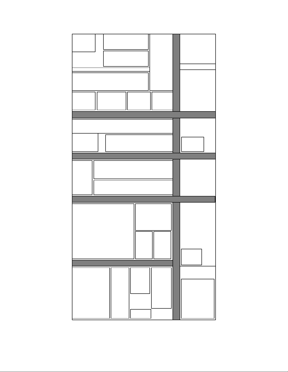
customers. A layout of the Machining Center is presented in Figure 1.1.
Machines are grouped by function, which provides the shop a great deal of flexibility. There are
50 numerically controlled (NC) machines with 3, 4 and 5 axis capabilities. There are also
manually operated mills, drills, lathes, as well as precision machines and deburring stations.
Presently, the shop runs a 5 days/3 shifts operation, fully manned on first shift with manpower
decreasing approximately by half in each consecutive shift. All the personnel involved in actual
production reports through supervisors to the Center Leader. The functions supporting
production such as Inventory Management, Manufacturing, Industrial, and Process Engineering
have representatives in the shop but report to their respective functional managers. 14 3 Ho r . Mi l l s ( FMS) , 1 Ho r . Mi l l , 3 A x i s , 3 A x i s , 1 S p i n d l e e a c h 3 S p i n d l e s Mai nt en a nc e Of f i c e 3 Ho r . Mi l l s , 2 V e r t . Mi l l s , 3 A x i s , 5 A x i s , 1 S p i n d l e Ea c h 3 Sp i n d l e s Ea c h 3 V e r t . Mi l l s , 3 A x i s , 3 S p i n d l e s Ea c h Of f i ce 2 Ho r . Mi l l s , 3 Ho r . Mi l l s , 2 Ho r . Mi l l s , 4 A x i s , 5 A x i s , 4 A x i s , Of f i ce 1 S p i n d l e Ea c h 1 S p i n d l e Ea c h 1 S p i n d l e Ea c h 4 Ho r . Mi l l s , 3 A x i s , Conv ent i ona l 1 S p i n d l e Ea c h Mi l l s A r e a L a y o u t A r e a T o o l Cr i b 4 V e r t . Mi l l s , 5 A x i s , 2 Ho r . Mi l l s , 3 S p i n d l e s Ea c h 5 A x i s , Of f i ce 1 S p i n d l e Ea c h 5 Ho r . Mi l l s , 5 A x i s , 1 Sp i n d l e Ea c h Pr eci si on 2 Ho r . Mi l l s , Ma c h i n i n g A r ea Di s pat c h 5 A x i s , Of f i ce 1 S p i n d l e Ea c h Con v en t i ona l Dr i l l s St a gi ng A r e a Rac ks 2 V e r t . 2 Ho r . Conv ent i ona l Mil l s, Mi ll s, Mi l l s I nc om i ng 3 A x i s , 5 A x i s , A r ea a n d V e n d o r 1 Sp i n d l e 1 S p i n d l e Of f l oad Ea c h Ea c h Of f i ce De bu r r A r ea St ag i ng Smal l Co n v . Rac k s Par t s Saw s Qu a l i t y A r e a A r e a A s s ur a nc e ( QA ) A r ea S h o t P e e n
Figure 1.1 Machining Center Layout 15
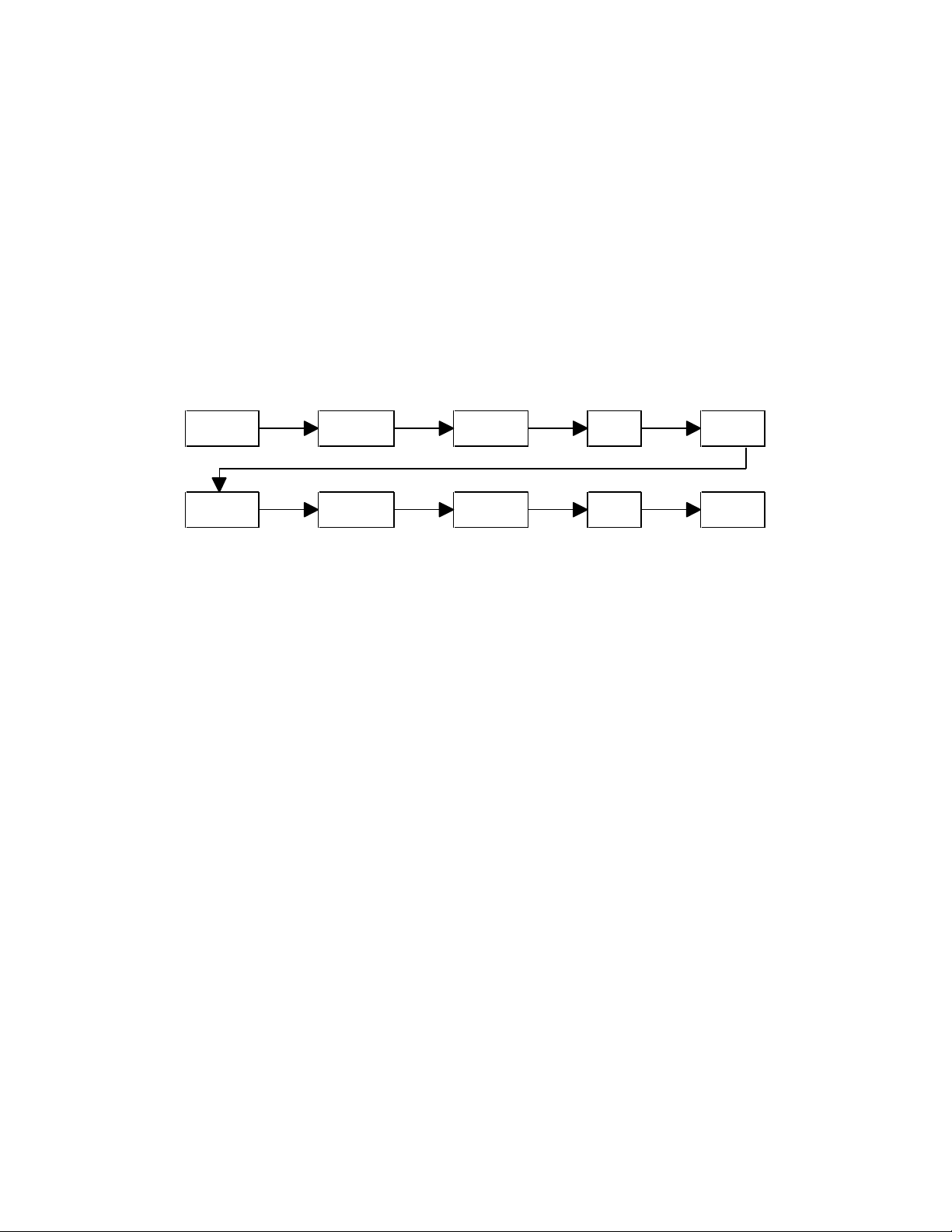
The process flow for a typical part is presented in Figure 1.2. As shown, after the machining
operations and the first QA step, which verifies the accuracy of the machining, parts go through a
Chemical Processing step. This step occurs in another D&SG manufacturing center, albeit
adjacent to the Machining Center. As a different center, the Chemical Process Line has its own
management and dedicated support personnel. Approximately 70% of the parts return to the
Machining Center or go to another manufacturing center after Chemical Processing for further
precision machining and/or subassembly work before completion. Therefore, at least two centers
are involved in the production of a finished product. Issue NC Manual Deburr QA Material Machining Machining Chemical Precision Sub Ship to QA Processing Jig bore Assembly Customer
Figure 1.2 Typical Part Process Flow
The Center processes between 350 to 400 orders a week. The shop floor control program does
not make a distinction between new orders, i.e. orders that are just starting the manufacturing
process as raw material, and orders that have been in the pipeline for some time and return to the
Machining Center for further processing. It only acknowledges orders “clocked” to one of the
areas in the Center. Therefore, of the total orders processed weekly, approximately 75% are new
orders; the rest are orders that return to the Machining Center after Chemical Process or another
Center or supplier for further machining or subassembly. The average backlog is five weeks
worth of work, i.e. between 1400 and 1600 orders. 1.2.1 Customers
The Machining Center supports two main customers: military and commercial programs. Figure
1.3 presents the current breakdown of the work in the Machining Center by customer as
percentages of the total direct labor hours. These two major customers are quite different in
nature, and the differences are explained below. 16 Commercial Emergent 2% F22 Program 19% Commercial Programs 43% Other Military Programs 36%
Figure 1.3 Current Work Breakdown by Customer in the Machining Center as Percentages of Factory Direct Labor Hours
Military programs have a finite life cycle. After the engineering design phase, one or more
prototypes are built before the approval for final production is obtained. The prototype stage is
generally very labor intensive, as the Center’s work force is learning how to make highly precise
and complicated parts. The F-22 program, now at the end of the prototyping stage, is a case in
point. First, the Center’s machinist and operators had to learn how to precision machine
complicated titanium parts. In the past, most of the machining had been done in steel or
aluminum, and titanium has different properties making it a difficult material to machine. Next,
the Center’s work force was faced with working through many engineering design changes.
Although necessary, these changes are very time consuming. Before making a final prototype
part on the desired material, the machinists run trials on less expensive material to show that the
numerically controlled machines are rendering the correct part geometry. This is an iterative
process, often requiring several trials before producing the desired part. When design changes are
introduced, the try-out process begins all over again. Thus for complex parts requiring long
machining times the prove-out process is very resource and time intensive. Once the production
stage begins, the Center is contracted to spend several years producing parts for a military
program, yet the production could still be characterized as low to medium volume . When all the 17
contract units are completed, no more parts are manufactured. It is worth noting that at any given
time, the Machining Center is generally dealing with several military programs at different points
in their life cycle. When a large program like the F-22 is in its prototype stage, the work load at
the Center is very high during this period, as a result of the learning curve effect and the number
of design changes required. Since there are parts for other customers in production at the same
time, the learning and design change activities affect the capacity of the Center significantly, and
therefore its ability to serve all of its customers.
According to Figure 1.3, almost half of the work at the Machining Center is performed for
commercial customers, i.e. the 737 through 777 programs. The majority of these parts are made
out of aluminum and have been in production for many years. Currently, commercial customers
place orders for parts up to two years in advance. Since the production of commercial planes is
continuous and at a known rate, there is little uncertainty in the demand. In the future, with the
introduction of DCAC/MRM, Boeing’s new resource planning system, orders may not be known
as far in advance and shorter lead-times may be required, but BCAG will continue to issue
medium to long term contracts with suppliers, which still reduces uncertainty from forecasting and
planning at the supplier level.
However, the Center is also expected to produce parts for AOG’s (Airplane On Ground) and
replenishment spares. Boeing’s service policy is to deliver parts for its planes as soon as a
customer, generally an airline, reports a grounded plane. When this happens, the needed part is
generally expedited through the shop, causing some disruption in production. The Machining
Center also supports some emergent production for commercial customers. Emergent work
refers to work that is generally done by BCAG’s fabrication division or BCAG suppliers, but due
to lack of capacity or some other reason, it cannot be performed by them in a timely fashion. This
work comes into the Machining Center on a one time basis. By accepting emergent work, the
Center supports its commercial customers by providing capacity and expertise to manufacture
parts. Emergent work causes uncertainty in the production schedule, but it is accepted in spite of
this fact, as the Center traditionally has valued supporting its commercial customer. To a certain 18
extent, the Center also expects that BCAG will return the favor during “slow” times by providing
the shop with emergent or long term work to efficiently utilize available capacity.
1.2.2 Business Process Flow
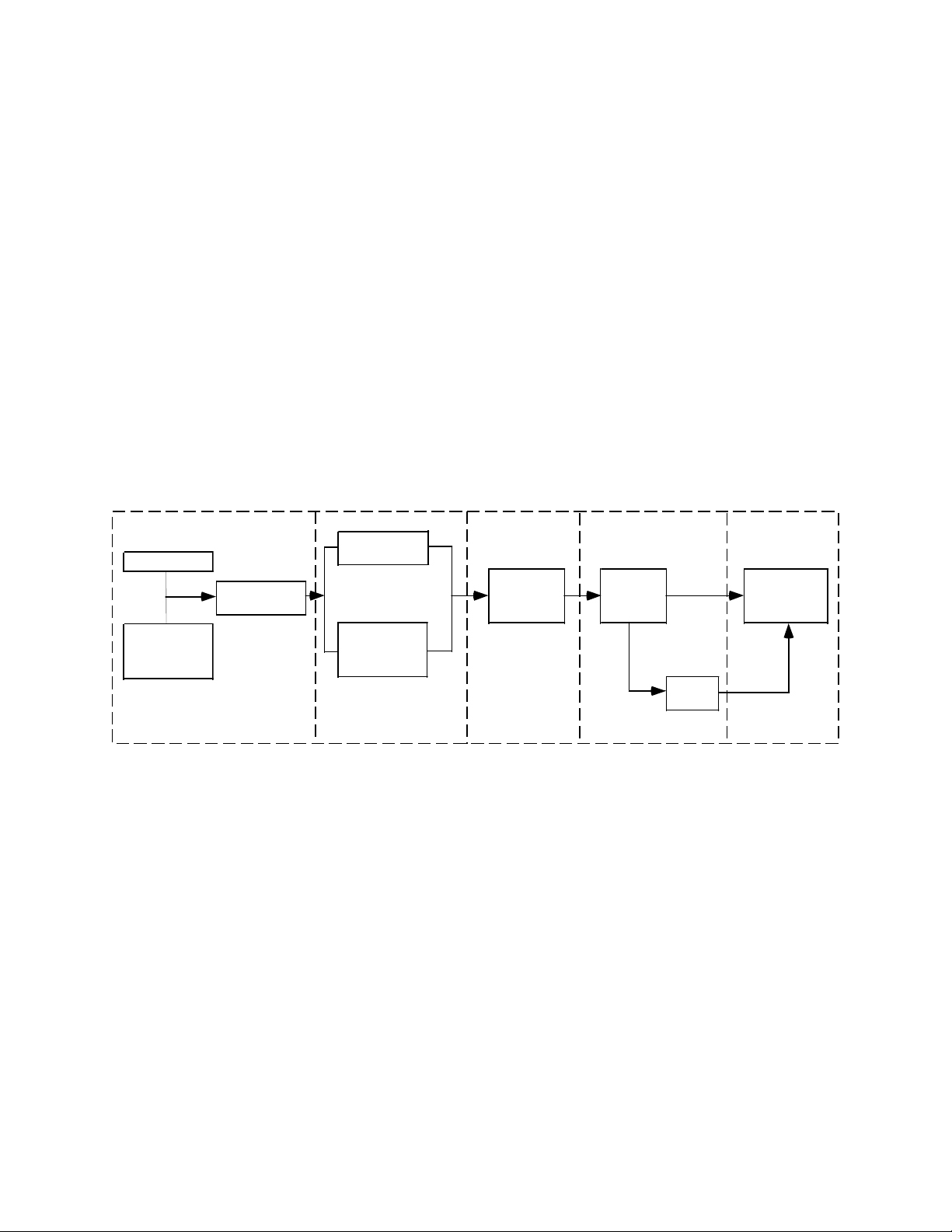
Figure 1.4 illustrates a simplified business process flow for Boeing’s D&SG. This flow is
composed of five major steps, which are described below, and it applies to both military and
commercial customers. The process is controlled at the Group level, and supported by a myriad
of computer applications, some of which have been in use for many years. Re ce iv ing , Pro c ur em en t an d St o re s and Re quire m e n t s Req uir em ent s Req uir em ent s Manuf ac t uring Con t rac t A u t ho riz at io n De v e lo p m e nt Pla n nin g Ord er Re leas e Co m plet io n Mast er Cust o m e r Sch ed ule Ord er En g ine e ring Ord er Creat io n Mat eriel Relea se Co m plet io n (MP&R) Pr o gr am Plan nin g Manage m ent Relea se Sh o p
Figure 1.4 Boeing Defense and Space Business Process Flow
During the first step, Requirements Authorization, the scope and schedule of the work is defined
by the customer, and by Boeing’s Program Office and Engineering. Engineering is completed
during this stage, and an account to pay for all the work concerning the contract is established.
Next, in the Requirements Development step, the part plans specifying where and how the parts
are to be built are completed by the planners, and the date in which the part is needed is
determined. The D&SG shop or supplier involved in the manufacturing of the part is chosen and
specified in the part plan. In the case of machined parts, NC programming is also completed at
this stage. The Inventory Management Organization marries the schedule requirement with the 19
part plan in the MP&R (Material Planning and Release) system to create an order. In the third
step, Requirements Planning, the orders are basically in a holding tank prior to release. At this
time any discrepancies or problems with the order are reviewed. In addition, the MP&R system
checks for availability of raw material and/or purchased parts and notifies materiel of needs, so
that they are procured prior to order release.
In the Procurement and Manufacturing Order Release stage, orders are released in the MP&R
system six days before the order is due at the first step of its manufacturing process as prescribed
by the plan to ensure that the engineering drawings and manufacturing plans are ready on the
order start day. For example, if the order flow time is 40 days, the order will be released 46 days
prior to its due date. Flow times are explained in more detail in the next section. This allows for
all the paperwork associated with an order to be created and ready in a timely manner. In the case
of purchased parts the same process is followed, and the supplier lead time is used. The final step
involves Receiving, Stores and Contract Completion. Once the orders are completed, they are
sent to D&SG stores from where they are shipped to the customers. Stores performs a final
inspection and completes the paper work to invoice the customer.
1.2.3 Capacity Planning Systems
It is important to understand the underlying assumptions driving D&SG capacity decisions. The
MP&R system currently being used has no capacity planning capability; it assumes that capacity is
infinite. Since this is not the case, capacity charts are developed to avoid accepting work in
excess of the capacity of the shop, and Puget Sound Flows are used to plan this work. Puget
Sound Flows are basically planned lead times; the concept is explained in more detail later in this
section. In other words, there are methods in place to accommodate long and short term capacity planning decisions.
The shop load committee, whose members are primarily industrial and manufacturing engineers
directed by the Center’s business manager, determines the amount of work in hours awaiting each
Factory Work Code (one or one group of machines with similar capabilities) in the shop twice a 20
Tài liệu liên quan:
-

Các yếu tố ảnh hưởng đến quang hợp và năng suất cây trồng trong nông nghiệp
10 5 -

Tổng hợp hình ảnh hải sản - Cua, Tôm, Bào ngư Môn Quản trị sản xuất và tác nghiệp | Trường Học Viện nông nghiệp Việt Nam
97 49 -

Quy Định Hợp Tác Xã (HTX) - Điều Lệ và Mục Tiêu Hoạt Động Môn Quản trị sản xuất và tác nghiệp | Trường Học Viện nông nghiệp Việt Nam
108 54 -
Chương 3: Xây Dựng Hệ Thống HACCP Cho Sản Phẩm Mì Gạo Môn Quản trị sản xuất và tác nghiệp | Trường Học Viện nông nghiệp Việt Nam
120 60