Multi-Sense CardioPatch: A Wearable Patch for Remote Monitoring of Electro-Mechanical Cardiac Activity | Thực tập cơ bản | Trường Đại học Bách Khoa Hà Nội
This study describes the conceptual design and the first proto-type implementation of the Multi-Sense CardioPatch. Tài liệu giúp bạn tham khảo, ôn tập và đạt kết quả cao. Mời đọc đón xem!
Môn: Thực tập cơ bản 331 tài liệu
Trường: Đại học Bách Khoa Hà Nội 5.6 K tài liệu
Tác giả:


Preview text:
ASAIO Journal 2017 Clinical Cardiovascular
Multi-Sense CardioPatch: A Wearable Patch for Remote
Monitoring of Electro-Mechanical Cardiac Activity
EMANUELA MARCELLI,* ALESSANDRO CAPUCCI,† GABRIELE MINARDI,* AND LAURA CERCENELLI*
This study describes the conceptual design and the first proto-
Heart sound (HS) is an acoustic signal that results from vibra-
type implementation of the Multi-Sense CardioPatch, a wear-
tions created by closure of heart valves, mainly the first heart
able multi-sensor patch for remote heart monitoring aimed
sound (S1) when the atrioventricular valves close at the begin-
at providing a more detailed and comprehensive heart status
ning of systole, and the second heart sound (S2) when the aor-
diagnostics. The system integrates multiple sensors in a single
tic valve and pulmonary valve close at the end of systole. HS
patch for detection of both electrical (electrocardiogram,
signal is a well-known expression of cardiac mechanics, since
ECG) and mechanical (heart sounds, HS) cardiac activity, in
the amplitude of S1 reflects cardiac contractility,10–12 while dia-
addition to physical activity (PA). The prototypal system also
stolic pressure affects the amplitude of S2.13 HS signal is tradi-
comprises a microcontroller board with a radio communica-
tionally recorded using stethoscopes and phonocardiographs,
tion unit and it is powered by a Li-Ion rechargeable battery.
even if in recent years also accelerometers applied on the chest
Results from preliminary evaluations on healthy subjects have have been used.14–16
shown that the prototype can successfully measure electro-
We report the conceptual design and the assembly of a first
mechanical cardiac activity, providing useful cardiac indexes.
proof-of-concept prototype of a wearable multi-sensor patch
The system has potential to improve remote monitoring of
(Multi-Sense CardioPatch) that provides the remote monitoring
cardiac function in chronically diseased patients undergoing
of electro-mechanical cardiac activity. Compared with the patch
home-based cardiac rehabilitation programs. ASAIO Journal
systems already available on the market for cardiac monitor- 2017; 63:73–79.
ing, the Multi-Sense CardioPatch includes a sensor for record-
ing transthoracic cardiac vibrations related to HS (HS sensor),
Key Words: wearable, patch, electrocardiogram, heart
together with more standard sensors for electrical cardiac activity
sounds, accelerometer, sensor R
(ECG sensor) and physical activity level (PA sensor). The idea is to
ecent advances in sensor technology, microelectronics,
provide a wearable system for a more detailed and comprehen-
sive heart status diagnostics in patients undergoing home-based
cardiac rehabilitation programs, thanks to the simultaneous
telecommunication and data analysis techniques have enabled
detection of both electrical and vibromechanical cardiac activity.
the development and spread of wearable systems for patients’
remote monitoring.1 An emerging area is application of wear-
able sensors in outpatient cardiac rehabilitation. Methods 2,3 The current
capabilities of wearable systems include physiologic sensing and motion sensing. Overview of the System
1,4–6 Physiologic measures mainly com-
prise heart rate, respiratory rate, blood pressure, blood oxygen
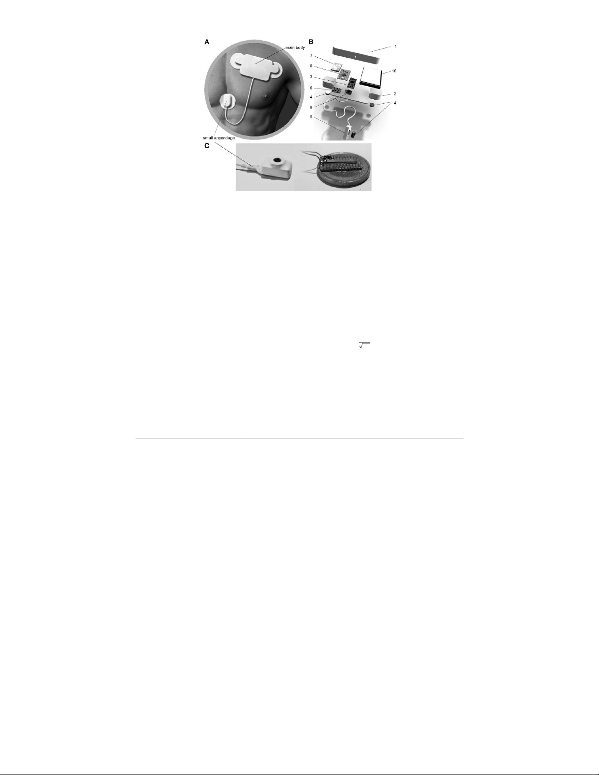
The Multi-Sense CardioPatch is a prototypal patch to be
saturation, and body temperature.6
applied on the chest, which comprises sensors and electron-
In the last years, a lot of work has been done about wearable
ics encapsulated in a flexible biocompatible silicon housing to
devices for remote monitoring of cardiopulmonary activity and
protect them from sweat and moisture. It is composed of two
many systems are now commercially available.7–9
parts: the main body and the small appendage (Figure 1A). The
All these systems have been mainly designed for continuous
main body is a silicon case (108 mm × 55 mm × 14 mm), which
monitoring of arrhythmias, including atrial fibrillation, as well
includes a standard module for ECG recording, a tri-axial
as patient falls that may be associated with arrhythmias; there-
MEMS accelerometer for PA recording, a radio communication
fore, they rely on electrocardiogram (ECG) sensors to monitor
unit (Bluetooth module), and all the electronics (microcon-
the electrical cardiac activity and on a tri-axial accelerometer
troller, conditioning circuits, battery). Two side wings protrud-
to record activity level and body position.
ing from the main body include two metal snaps for standard
disposable ECG electrodes (Figure 1B).
The appendage is a small silicon case (23 mm ×10 mm × 8 mm)
From the *Experimental Diagnostic and Specialty Medicine Depart-
comprising a miniature piezoelectric accelerometer for HS sens-
ment, University of Bologna, Bologna, Italy; and †U.O.C. Cardiologia
ing (HS sensor) and a third metal snap for the reference ECG elec-
Clinica, Università Politecnica delle Marche, Ancona, Italy.
trode (Figure 1A). The appendage allows to adjust the position of
Submitted for consideration February 2016; accepted for publica-
tion in revised form September 2016.
the piezoelectric accelerometer on the chest to detect the highest
Disclosures: The authors have no conflict of interests to disclose.
HS signal. The flexible silicon material used for both the main
Correspondence: Laura Cercenelli, Università di Bologna, Dip. Medic-
body and the small appendage allows a good adaptation of the
ina Specialistica, Diagnostica e Sperimentale, c/o Sezione Tecnologie
patch to the chest’s shape. Adhesion to the thorax is ensured by
Biomediche, Policlinico S. Orsola Malpighi, Via Massarenti 9 (pal.17 – 2°
three standard adhesive button electrodes used for ECG recording.
piano), 40138 Bologna, Italy. Email: laura.cercenelli@unibo.it. Copyright © 2016 by the ASAIO
Data from HS, ECG, and PA sensors are preliminarily pro-
cessed (sampling and preliminary signal conditioning) by the
DOI: 10.1097/MAT.0000000000000446 73
Copyright © American Society of Artificial Internal Organs. Unauthorized reproduction of this article is prohibited. 74 MARCELLI
Figure 1. Multi-Sense CardioPatch prototype (A) and its explosion view (B): 1. cover of the main body; 2. “wings” including ECG electrodes;
3. ECG module; 4. ECG electrodes; 5. appendage including HS sensor; 6. amplifier module for HS sensor; 7. Bluetooth module; 8. microcon-
troller; 9. tri-axial accelerometer for PA sensing; 10. battery. (C) Cantilever accelerometer used for HS sensor.
microcontroller, then sent via Bluetooth connection to a note-
data provided by the sensors included in the patch. Data sav-
book for real-time display and further signal processing.
ing can be controlled by soft keys on the GUI.
Electrocardiogram processing. A band-pass filter (10–30 Hardware
Hz) is applied to the acquired ECG signal to isolate the pre-
dominant QRS components and to attenuate the low frequen-
Sensors. The ECG sensor is a custom design composed of
cies of P and T waves, as well as to remove the baseline drift
1-lead recording provided by the two disposable ECG elec-
and the power line interference. The filtered signal is differ-
trodes included in the side wings of the main body of the patch
entiated and squared to emphasize the QRS high-frequency
and the third reference electrode in the appendage, coupled to a
components and then integrated (by low-pass filtering, cutoff
signal conditioning module (gain 200, bandwidth 0.1–100 Hz).
frequency of 3 Hz) to obtain the processed ECG waveform re-
The HS sensor is a piezoelectric cantilever accelerometer
ported in Figure 2 ( upper panel, grey bold line). A peak de-
(285–784 M641, Sensor Technology, Collingwood, ON, Can-
tector algorithm, based on a dynamic threshold, finds R-peaks
ada), with sensitivity of 80 mV/g, which detects the transthoracic
in the processed ECG waveform and the corresponding times
propagation of cardiac vibrations due to HS (Figure 1C). The
(TQRS), thus providing R–R intervals and heart rate (HR).
sensor, coupled to a transistor and a signal amplifier module
To detect T wave, a band-pass filter (0.5–30 Hz) is applied
(gain 200, bandwidth 5–155 Hz), is included in the appendage.
to the acquired ECG signal. Then, T-peak is searched within a
The PA sensor is a tri-axial MEMS accelerometer (ADXL335,
window that starts at TQRS and ends after a period equal to QT
Analog Devices, Norwood, MA) with a detection range of ± 3 g, interval estimated by using the Bazett’s formula, Equation 1.17
sensitivity of 500 mV/g, bandwidth 0–45 Hz.
Electronics and wireless communication. A microcon- =3.5
troller board (Arduino Pro Mini 328-5V/16MHz, Sparkfun, QT HR (1)
Niwot, CO) is used to sample the data collected by ECG, HS,
and PA sensors and to send them to a notebook via a Bluetooth
module (RN42, Roving Networks, o L s Gatos, CA) with baud
For P wave detection, the software estimates a dynamic tem-
poral window (P wave window) that starts at t = (T
rate 115200. The prototypal patch is powered by a Li-Ion re- QRS − 20% of
cardiac cycle duration) and ends at t = T
chargeable battery with 1,000 mAh capacity. QRS.
Heart sound processing. HS processing is strictly related to
ECG processing (Figure 2). The acquired HS signal is prelimi-
Software and Data Processing
nary differentiated, squared, and low-pass filtered (cutoff fre-
Graphical user interface. A dedicated program and graphi-
quency 10 Hz). Two searching windows for S1 and S2 analysis
cal user interface (GUI) were developed in ab L VIEW (National
are selected on the basis of the identified QRS complex, T wave,
Instruments, Austin, TX) to acquire, process, and display the
and P wave window: S1 is searched within a temporal window
Copyright © American Society of Artificial Internal Organs. Unauthorized reproduction of this article is prohibited.
WEARABLE PATCH FOR ELECTRO-MECHANICAL CARDIAC MONITORING 75
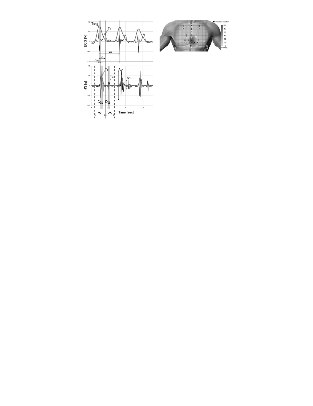
Figure 3. Topographic mapping of the thorax for S1 detection
(results from averaging AS1 data from 19 subjects).
categorized as motion conditions according to a preliminary
calibration procedure where several basic static and dynamic
body motions (e.g., stretches, walking, running, falls) are carried
out by a subject wearing the Multi-Sense CardioPatch.
Cardiac indexes. The implemented data analysis provides
indexes of both electrical (HR, QT interval) and mechanical
(AS1, AS2, DS1, DS2) cardiac activity. Additionally, by combining
simultaneous recordings of ECG and HS signals, cardiac time in-
tervals related to the electro-mechanical cardiac activity can be
derived. An interesting index that the implemented data analysis
calculates is QS1,18,19 i.e., the time interval from the onset of
QRS complex to the beginning of S1, as reported in Equation 2. QS = S S Q 1 RS 2 ( ) T- D / - T (2) 1 1
QS1 is the major component of the pre-ejection period
(PEP), which is a commonly used index of myocardial con-
Figure 2. Example of ECG, HS recordings (black lines), and the
tractility and sympathetic control of the heart.18,19 It has been
corresponding processed waveforms (grey bold lines). AS1: esti-
widely demonstrated that in heart failure patients, because of
mated S1 amplitude; AS2: estimated S2 amplitude; DS1: estimated
systolic dysfunction, there is a relevant prolongation of QS1
S1 duration; DS2: estimated S2 duration; HR: heart rate; QS1: inter-
val from onset of QRS to S1; QT: time interval between TQRS and
interval, as well as a reduction of left ventricular ejection.18,19
TT; TQRS: time of R-peak; TT: time of T-peak; TS1: time of S1-peak;
TS2: time of S2-peak; W1: searching window for S1; W2: searching In Vivo Evaluation window for S2.
We evaluated the Multi-Sense CardioPatch on 19 healthy vol-
(W1) from the start of P wave window to the time of T-peak (TT),
unteers. Preliminary tests were performed to evaluate the opti-
while S2 is searched within a temporal window (W2) from TT to
mal HS sensor position on the chest (“Positioning tests”) and to
the following start of P wave window (Figure 2).
compare, in three different body types, the HS sensor recordings
Amplitudes (AS1, AS2) and durations (DS1, DS2) of the two most
with a phonocardiography (PCG) signal (“Comparative tests”).
relevant HS components (S1, S2) are calculated: 1) a peak detec-
Finally, the 19 volunteers underwent a step-climbing exercise
tor algorithm is applied to the processed HS signal (grey bold
and their electro-mechanical cardiac activity was monitored
line in bottom panel of Figure 2) to find peaks within W1 and
with the Multi-Sense CardioPatch at the maximum workload
W2; 2) DS1 (DS2) is calculated as the time interval between the
condition and during recovery after exercise (“Exercise tests”).
instants when the processed HS signal falls below 50% of its
All tests were performed with informed consent from the
peak, by moving back and forth with respect to the time of the
volunteers and following the principles outlined in the 1964
peak (TS1 (TS2)); 3) the peak-to-peak amplitude of the acquired
Helsinki declaration and its later amendments or comparable
HS signal within DS1 (DS2) interval is associated to AS1 (AS2). ethical standards.
Physical activity processing. In this first prototype, accelera-
Positioning tests. For each subject, we explored 15 differ-
tion data retrieved from the PA sensor are mainly used to provide
ent positions of the HS sensor on the chest (Figure 3). For each
an ON/OFF algorithm to reject from the automatic analysis those
position, the peak-to-peak amplitude of the first heart sound
ECG and HS recordings affected by motion artifacts (“motion-re-
component (AS1) was considered and for each subject, a rep-
jection algorithm”): the acceleration modulus is calculated from
resentative mean value of AS1 (average of 20 heartbeats) was
the X, Y, Z-axis components of the tri-axial MEMS accelerometer
calculated. Representative mean values from the 19 subjects
and it is continuously compared with a predefined threshold
were averaged and a topographic mapping of the thorax for
value that discriminates between motion and rest conditions.
S1 detection was obtained by interpolating the representative
The threshold can be set to fine or coarse increment to interpret
AS1 values within a rectangular region included in an averaged
various g-values of the acceleration modulus: these g-values are thorax size (Figure 3).
Copyright © American Society of Artificial Internal Organs. Unauthorized reproduction of this article is prohibited. 76 MARCELLI
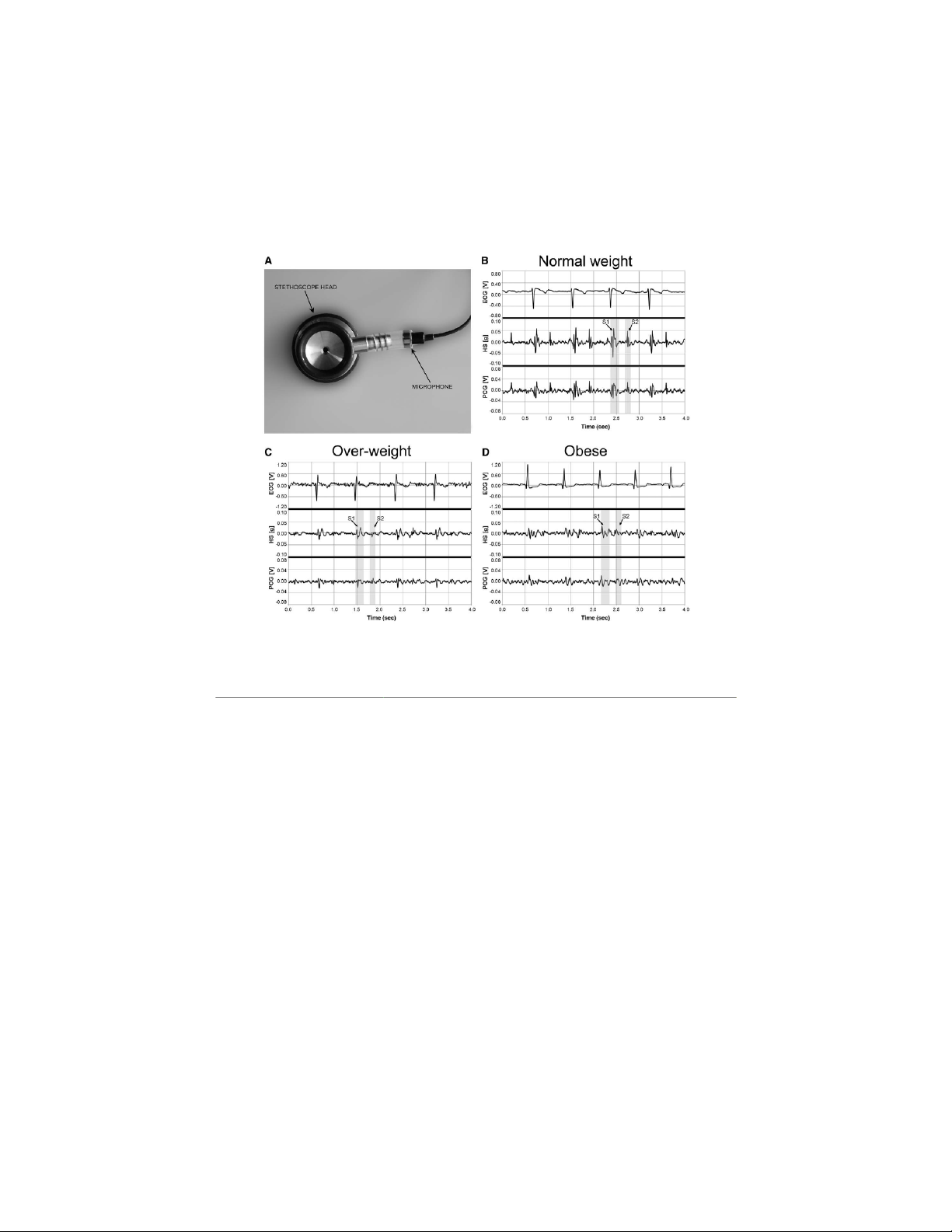
Comparative tests. We considered three subjects repre-
exercise protocol with a peak workload of 2,000 J. The end-
sentative of different body types in the group of volunteers: 1)
point of the exercise test was the achievement of the designed
normal weight (body mass index, BMI = 19.4); 2) over-weight
exercise workload. Immediately after exercise, recordings us-
(BMI = 27.4); 3) obese (BMI = 47.9). The PCG signal was
ing the Multi-Sense CardioPatch were continuously performed
acquired using a self-developed electronic stethoscope com-
with the subject laying in supine position, for 8 minutes of re-
posed of a standard stethoscope head connected to an elec-
covery after exercise. Real-time signal recordings and cardiac
trect condenser microphone (Lavalier RS Pro) with frequency
indexes derived from data processing were displayed on the
response window from 30 Hz to 18 kHz. The microphone
GUI and saved. Electrical (ECG) and mechanical (HS) cardiac
was coupled to the stethoscope head using a piece of PVC
signals corresponding to any possible body motion as detected
tubing, as shown in Figure 4A, and the output of the micro-
by the PA sensor (“motion-rejection algorithm”) were automat-
phone was connected to the PC through an audio input jack.
ically excluded from the analysis.
The HS sensor and the self-developed electronic stethoscope
Statistics. The cardiac indexes, collected for both the maxi-
were positioned in the same most sensitive sternal region on
mum workload condition and the final recovery condition,
the chest, and simultaneous recordings of cardiac vibrations
were expressed as mean ± SD, obtained by averaging 10 car-
from the two systems were provided for each body type, at
diac cycles for each condition. rest conditions.
Relations between the cardiac indexes were assessed using
Exercise tests. Each subject in the group of 19 volunteers
linear regression analysis and Pearson’s correlation coefficient.
was engaged in a step-climbing exercise following a designed
A probability value of p < 0.05 was considered significant.
Figure 4. Results from tests to compare HS signal provided by the patch with a standard phonocardiogram (PCG) signal: (A) the self-
developed electronic stethoscope, made of a stethoscope head connected to a microphone; ECG, HS, and PCG signals obtained for three
different body types: normal weight (B); over-weight (C); obese (D).
Copyright © American Society of Artificial Internal Organs. Unauthorized reproduction of this article is prohibited.
WEARABLE PATCH FOR ELECTRO-MECHANICAL CARDIAC MONITORING 77 Results
attenuates the higher frequencies and probably introduces a
variable propagation delay. This makes reason of a vibrational
From positioning tests, the most sensitive region for S1
signal less powerful than the myocardial vibrations recorded
detection using the HS sensor was the most inferior part of
endocardially, but it can be still considered a good signal for
the sternum, i.e., the xiphoid process (position 10 in Figure 3).
assessing changes in myocardial contractility.14 Our results for
Comparative tests showed that the HS sensor is effective to
AS1 are consistent with peak values of transthoracic cardiac
acquire heart sound vibrations: in accordance with previous
vibrations previously recorded in healthy subjects by the cuta-
literature on seismocardiography (SCG),14–16 we found a corre-
neous precordial application of an accelerometer sensor.14
spondence between the waves composing the HS sensor signal,
Comparative tests showed that HS signal is reflective as
with distinctive systolic (S1) and diastolic (S2) components, and
much as PCG signal of heart sound vibrations. Indeed, com-
those composing the acoustic signal (PCG signal) detected with
pared with PCG signal, the seismocardiographic signal has
the self-developed electronic stethoscope ( Figure 4). In over-
the advantage of not being contaminated by acoustic noises
weight and obese types, both the PCG and HS signals seem to occurring in the environment.
be attenuated, probably because of the fat layer (Figure 4).
The key advantage of our patch is the capability of assess-
Exercise tests performed for all subjects confirmed the capa-
ing simultaneously both the electrical and mechanical cardiac
bility of the Multi-Sense CardioPatch of measuring stable,
activity, thus providing useful indexes of electro-mechanical
reproducible, and consistent signals for ECG and transthoracic
cardiac performance (e.g., QS1 interval) that can be impaired
cardiac vibrations related to HS. in failing hearts.
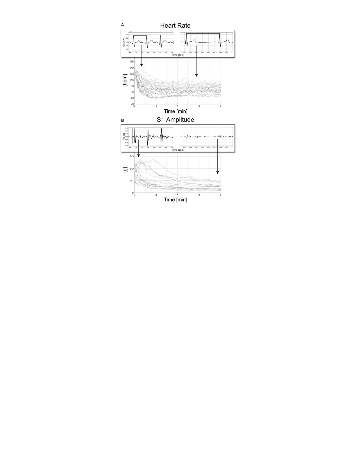
For all subjects, the cardiac indexes provided by the patch
In this preliminary study, we performed only measurements
and their relationship were consistent with normal electro-
on healthy subjects, who have a normal response to exercise,
mechanical behavior in nondiseased hearts: in response to
characterized by a positive correlation between contractility
exercise, cardiac contractility (AS1) increases with increases
(mechanical function) and HR (electrical function). In failing
in HR and it recovers from maximal workload condition to
hearts, it is expected that this force–frequency relationship
final recovery (8 minutes after the end of exercise), following
reverses from positive to negative: as a result, increases in HR
a decreasing trend similar to that observed for HR (Figure 5).
reduce contractility, impair exercise tolerance, and precipitate
In the group of subjects as a whole, mean AS1 decreased from
dyspnea and cardiac congestion.22 In heart failure patients,
0.17 ± 0.06 to 0.05 ± 0.03 g, and mean HR decreased from
the assessment of both HR and cardiac contractility (AS1), as
112 ± 23 to 64 ± 11 beats/min, when passing from maximum
provided by our patch, may be extremely useful to detect any
workload condition to final recovery condition. A significant
progressive reversion of this force–frequency relationship, or
positive correlation between AS1 and HR was found (r = 0.79,
any possible improvement of it after a cardiac rehabilitation
p < 0.05) when considering data collected for each patient program.
at maximal workload condition and at final recovery. A mild
In this study, we presented a first generation prototype of the
inverse correlation (r = −0.45, p < 0.05) was found between
Multi-Sense CardioPatch, therefore it still lacks of true wear- DS1 and HR.
ability. Future efforts will be directed to reduce the size and
Mean QS1 obtained for the whole group of volunteers at
the thickness of the patch to provide a most comfortable and
final recovery (48 ± 10 ms) was within the physiologic range for wearable solution.
healthy subjects at rest condition,19 and, in accordance with
Power consumption of the prototype is still high because we
the literature,18 we found that QS1 is inversely related to HR
employed general purpose electronics (e.g., Arduino Pro Mini
(r = −0.72, p < 0.05).
and standard Bluetooth radio module) that require from 60 to
Automatic identification/processing of S2 (AS2, DS2) was not
100 mA. This, with a battery of 1,000 mAh, provides at most
always reliable, because of the low level of S2.
10–15 hours of operation. New generation of microelectronic
systems for wearable medical electronics, such as the recently Discussion
standardized Bluetooth low energy (B E) L technology and the
ultra-low-power ECG System on Chip (ECG SoC)23,24 could be
The Multi-Sense CardioPatch presented in this study expands
employed in a new version of the Multi-Sense CardioPatch to
the physiologic sensing capabilities of wearable systems for
lower power consumption and increase the system lifetime.
heart monitoring, by providing the combination of HS, ECG,
Another critical issue with the current first-generation pro-
and PA recordings. The simultaneous recordings of electri-
totype of Multi-Sense CardioPatch is related to artifacts on
cal (ECG sensor) and mechanical cardiac activity (HS sensor)
the HS signal because of body accelerations (e.g., vibrations
might be beneficial for a more comprehensive evaluation of
due to cough, speech, and motion) retrieved by the HS sen-
cardiac function recovery in patients undergoing cardiac reha-
sor attached on the chest. Motion artifacts represent the major bilitation programs.
obstacle for the evolution of systems based on SCG toward
It has been previously shown that the peak of the myocar-
daily-life monitoring. Some recent studies25–27 have been
dial vibrations occurring in the isovolumic contraction phase
specifically addressed to the challenging aim of removing
(the absolute peak value of first heart sound), detected endo-
motion artifacts from SCG recordings, and they have achieved
cardially using an implantable accelerometer, is an index of
promising results. Pandia et al.25 implemented a polynomial
myocardial contractility and that its directional changes mirror
smoothing filter to cancel motion artifacts in walking sub-
changes in left ventricular peak dP/dt very closely.20,21
jects and their preliminary results showed a primary heart
Our HS sensor is positioned on the chest, therefore it detects
signal detection rate of 99.36% with a false positive rate of
the transthoracic cardiac vibrations that propagate as mechani-
1.3%. Di Rienzo et al.26 developed an algorithm that selects
cal shear waves, and the intervening viscoelastic thoracic tissue
movement-free data segments from 24 hour recordings of SCG
Copyright © American Society of Artificial Internal Organs. Unauthorized reproduction of this article is prohibited. 78 MARCELLI
Figure 5. Signal trends recorded during the Exercise tests: (A) Heart Rate, (B) S1 amplitude (AS1), both recorded with the Multi-Sense Car-
dioPatch: in the foreground boxes, there are examples of ECG and HS signals recorded at maximal workload condition (left side) and after
8 minutes of recovery (right side).
from ambulant subjects. Yang et al.27 recently proposed a novel
by motion artifacts. This obviously limits the HS processing
method of extracting seismocardiographic data from moving
to a “controlled” condition (e.g., patient at rest, no speak-
adult subjects, using a digital signal processing system based
ing). Taking as reference the above-mentioned recent works
on the normalized least mean square adaptive filter, achieving
on motion artifacts cancellation for SCG applications,25–27
a detection rate of SCG recordings of 96% in moving subjects.
signal processing algorithms will be studied to provide dis-
In our early stage prototype, we used the PA sensor to
crimination and automatic removal of artifacts accelerations
exclude from data processing those HS acquisitions affected from HS signals.
Copyright © American Society of Artificial Internal Organs. Unauthorized reproduction of this article is prohibited.
WEARABLE PATCH FOR ELECTRO-MECHANICAL CARDIAC MONITORING 79
Further improvements of the Multi-Sense CardioPatch pro- 1 1. Hansen PB, u
L isada AA, Miletich DJ, Albrecht RF:
totype will include the following: optimization of the process-
Phonocardiography as a monitor of cardiac performance dur-
ing anesthesia. Anesth Analg 68: 385–387, 1989.
ing algorithms to provide a more reliable identification of the
12. Stept ME, Heid CE, Shaver JA, eo L n DF, eo L nard JJ: Effect of alter-
second heart sound component (S2); optimization of the PA
ing P-R interval on the amplitude of the first heart sound in the
sensor processing to expand its use beyond the motion-rejec-
anesthetized dog. Circ Res 25: 255–263, 1969.
tion algorithm by improving the motion pattern recognition
13. Sabbah HN, Stein PD: Investigation of the theory and mechanism
analysis; implementation of patient’s data transmission to a
of the origin of the second heart sound. Circ Res 39: 874–882, 1976.
mobile phone or to an access point to relay the information to
14. Bombardini T, Marcelli E, Picano E, et al: Operator independent
a remote center via Internet.
left ventricular function monitoring during pharmacological
stress echo with the new peak transcutaneous acceleration sig-
nal. Heart 85: 286–289, 2001. Conclusion
15. Zanetti JM, Salerno DM: Seismocardiography: A technique for
recording precordial acceleration. Proceedings of the 4th
We have presented the conceptual design and the first
Annual IEEE Symposium Computer-Based Medical System
prototype implementation of the Multi-Sense CardioPatch, 1991:4–9, 1991.
a wearable patch designed to remotely monitor the electro-
16. Jain PK, Tiwari AK, Chourasia VS: Performance analysis of seis-
mechanical cardiac activity. A preliminary evaluation of the
mocardiography for heart sound signal recording in noisy sce-
Multi-Sense CardioPatch has been performed in 19 healthy
narios. J Med Eng Technol 40: 106–118, 2016.
17. Bazett HC: An analysis of the time-relations of electrocardiograms.
subjects, with promising results. Further optimization of the
Heart 7: 353–370, 1920.
system is required, and then a larger scale evaluation on heart
18. Weissler AM, Harris WS, Schoenfeld CD: Systolic time intervals in
disease patients can be undertaken.
heart failure in man. Circulation 37: 149–159, 1968.
19. De Oliveira NR, Pinheiro MA, Carriço AS, Santos de Oliveira MM, References
Camara MF, Lagreca RJ: Abnormalities of the systolic time inter-
vals obtained by electronic stethoscope in heart failure. Internet
1. Patel S, Park H, Bonato P, Chan , L Rodgers M: A review of wear- J Cardiol 5: 2, 2008.
able sensors and systems with application in rehabilitation.
20. Marcelli E, Vanoli E, Mattera GG, et al: An endocardial accelera-
J Neuroeng Rehabil 9: 1–17, 2012.
tion sensor for monitoring cardiac function of ischemic hearts.
2. Ahsan A, Brahmbhatt A, Cantwell D, Melik-Martirosian A, Meyer
Journal of Mechanics in Medicine and Biology 6: 75–80, 2006.
JA: Wearable sensors for cardiac rehabilitation, in Insights in
21. Delnoy PP, Marcelli E, Oudeluttikhuis H, et al: Validation of a
Engineering Leadership White Paper, No. 2014.4.10, Apr 2014.
peak endocardial acceleration-based algorithm to optimize
3. Pollonini L, Dacso CC: Wearable sensing device for home monitor-
cardiac resynchronization: Early clinical results. Europace 10:
ing of cardiac rehabilitation, in AMAIEEE. Medical Technology 801–808, 2008.
Conference, Boston, USA, October 16th–18th, 2011.
22. Böhm M, La Rosée K, Schmidt U, Schulz C, Schwinger RH,
4. Teng XF, Zhang YT, Poon CC, Bonato P: Wearable medical systems
Erdmann E: Force-frequency relationship and inotropic stim-
for p-Health. IEEE Rev Biomed Eng 1: 62–74, 2008.
ulation in the nonfailing and failing human myocardium:
5. Bonato P: Wearable sensors and systems. From enabling technol-
Implications for the medical treatment of heart failure. Clin
ogy to clinical applications. IEEE Eng Med Biol Mag 29: 25–36,
Investig 70: 421–425, 1992. 2010.
23. Altini M, Polito S, Penders J, Kim H: An ECG patch combining
6. Andreu-Perez J, Leff DR, Ip HM, Yang GZ: From wearable sensors
a customized ultra-low-power ECG SoC with Bluetooth low
to smart implants–toward pervasive and personalized health-
energy for long term ambulatory monitoring, in Proceedings of
care. IEEE Trans Biomed Eng 62: 2750–2762, 2015.
Wireless Health ’11. San Diego, USA, October 10–13, 2011.
7. Barrett PM, Komatireddy R, Haaser S, et al: Comparison of 24-hour 24. Yang G, Xie ,
L Mantysalo M, Chen J, Tenhunen H, Zheng LR: Bio-
Holter monitoring with 14-day novel adhesive patch electrocar-
patch design and implementation based on a low-power sys-
diographic monitoring. Am J Med 127: 95.e11–95.e17, 2014.
tem-on-chip and paper-based inkjet printing technology. IEEE
8. Chan AM, Selvaraj N, Ferdosi N, Narasimhan R: Wireless patch sen-
Trans Inf Technol Biomed 16: 1043–1050, 2012.
sor for remote monitoring of heart rate, respiration, activity, and
25. Pandia K, Vijayraghavan K, Kovacs GT, Giovangrandi : L Physical
falls. Conf Proc IEEE Eng Med Biol Soc 2013: 6115–6118, 2013.
modeling of low-frequency sound propagation through human
9. Chakravarthy N, Engel JM, Chavan A, Finlay B, Nosbush G: A
thoracic tissue. Conf Proc IEEE Eng Med Biol Soc 2010: 2455–
study of activity and body posture with the PiiX mobile body- 2458, 2010.
adherent device. Conf Proc IEEE Eng Med Biol Soc 2014: 2714–
26. Di Rienzo M, Meriggi P, Rizzo F, et al: A wearable system for the 2717, 2014.
seismocardiogram assessment in daily life conditions. Conf
10. Durand LG, Langlois YE, Lanthier T, et al: Spectral analysis and
Proc IEEE Eng Med Biol Soc 2011: 4263–4266, 2011.
acoustic transmission of mitral and aortic valve closure sounds
27. Yang C, Tavassolian N: Motion artifact cancellation of seismocar-
in dogs. Part 4: Effect of modulating cardiac inotropy. Med Biol
diographic recording from moving subjects. IEEE SENSORS J
Eng Comput 28: 439–445, 1990. 16: 5702–5708, 2016.
Copyright © American Society of Artificial Internal Organs. Unauthorized reproduction of this article is prohibited.
Tài liệu liên quan:
-

Báo cáo Thực Tập Cơ Bản: Linh Kiện và IC Trong Mạch Điện | Thực tập cơ bản | Trường Đại học Bách khoa Hà Nội
41 21 -

Báo cáo Thực Tập Cơ Bản: Thiết Kế Mạch Điện Tử | Thực tập cơ bản | Trường Đại học Bách khoa Hà Nội
35 18 -
Báo cáo về Chủ nghĩa Xã hội Khoa học và Vai trò của C. Mác - Ph. Ăngghen | Thực tập cơ bản | Trường Đại học Bách khoa Hà Nội
40 20 -

Báo cáo Thực Tập Cơ Bản: Thiết Kế Mạch Đếm Thuận 0-9 Bằng Altium | Thực tập cơ bản | Trường Đại học Bách khoa Hà Nội
35 18 -
Báo cáo thực tập Mạch khuếch đại âm tần - Điện tử | Thực tập cơ bản | Trường Đại học Bách khoa Hà Nội
38 19