Reinforced Concrete 1 Tutorial 1: Load Combinations & Beam Design | Môn Engineering Drawing - Trường Đại học Quốc tế, Đại học Quốc gia Thành phố Hồ Chí Minh
Reinforced Concrete 1 Tutorial 1: Load Combinations & Beam Design Môn Engineering Drawing. Tài liệu được sưu tầm gồm 4 trang, giúp bạn ôn tập tốt hơn. Mời các bạn đón xem.
Môn: Engineering Drawing 4 tài liệu
Trường: Trường Đại học Quốc tế, Đại học Quốc gia Thành phố Hồ Chí Minh 2 K tài liệu
Tác giả:
Preview text:
lOMoAR cPSD| 58583460 International University
Department of Civil Engineering
CE304 – Reinforced Concrete 1
Tutorial 1: Loading, load combinations and singly reinforced concrete rectangular beams Question 1:
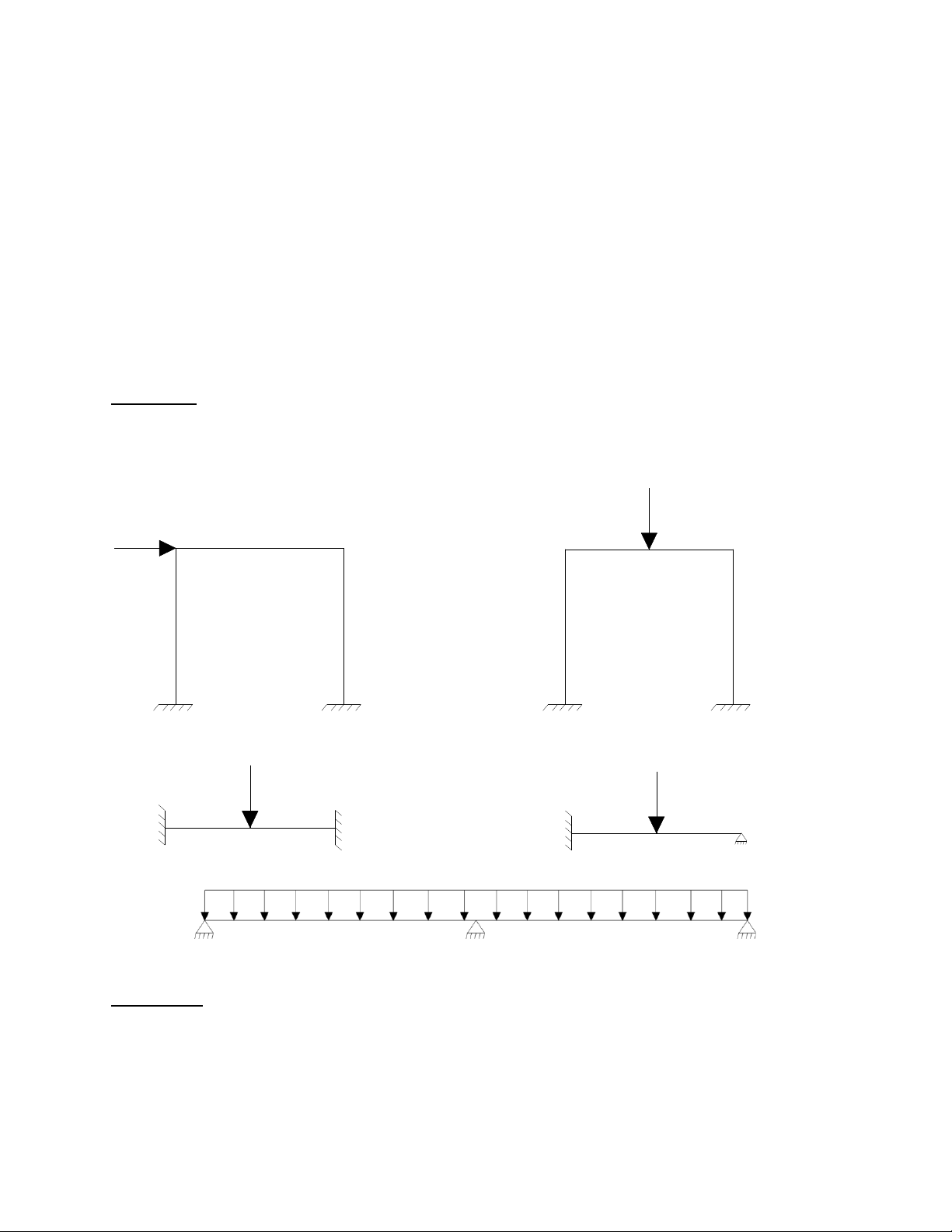
Draw the deformed shapes and determine the suitable locations of reinforcement for the following frames: (a) (b) (c) (d) (e) Question 2:
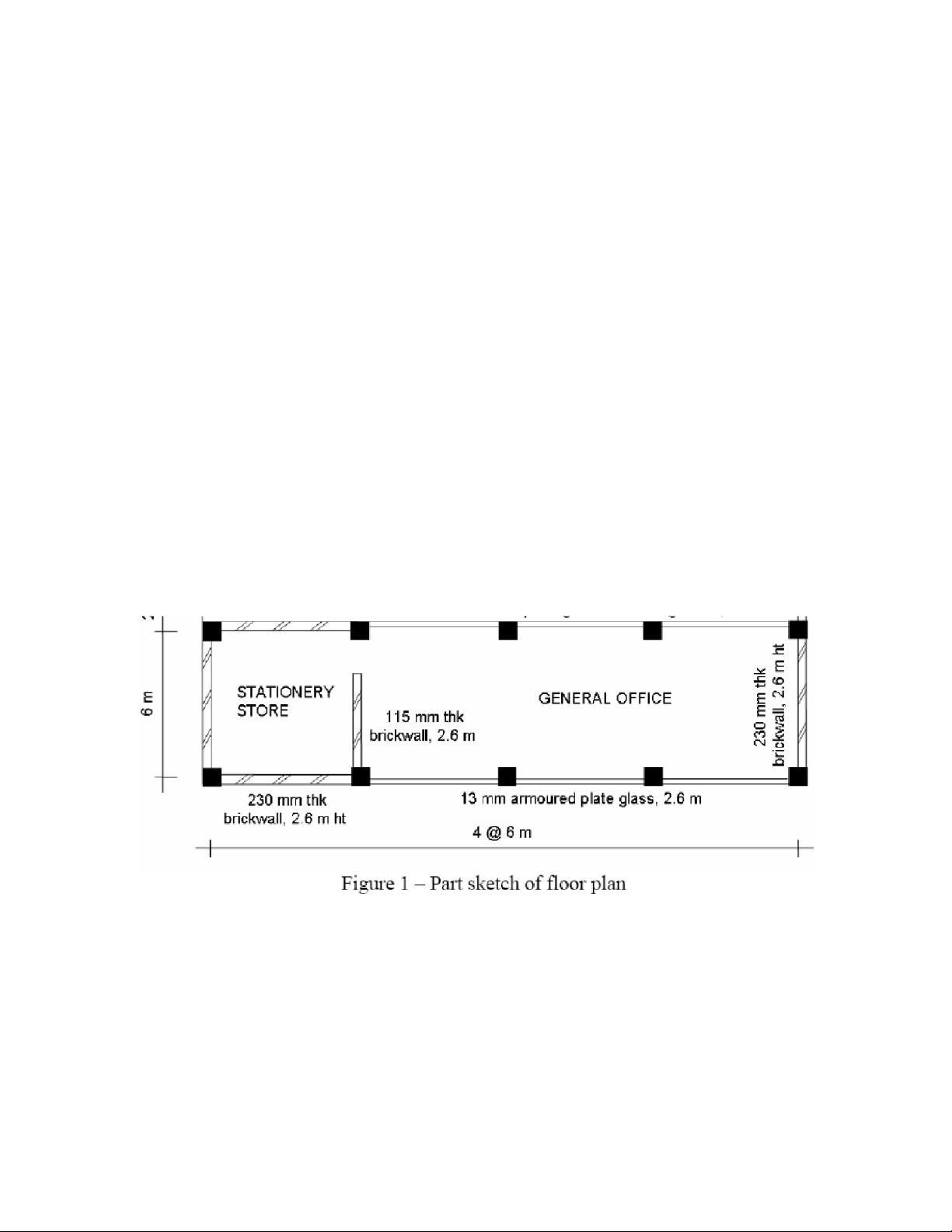
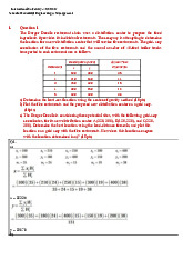
Figure 1 shows part of a floor plan for a typical office building. Estimate the permanent action (Gk)
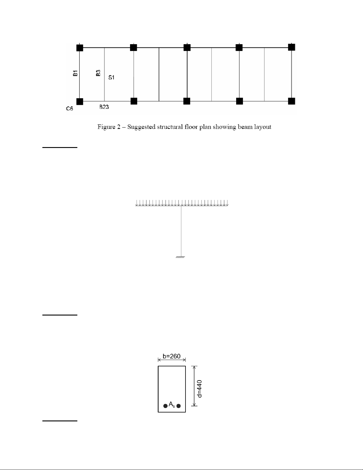
and variable action (Qk) carried by: lOMoAR cPSD| 58583460 a) Slab S1 b) Beams B1, B3 and B23
c) Column C6 (for one floor only)
For the purpose of load taking only, assume that the slabs and beams are simply-supported.
Structural elements are made of reinforced concrete of which a) Slab is of 125 mm thick
b) Beams are 300 mm width and has an overall depth of 500 mm c) Columns are 300 x 300 mm
Basic loading data are given as follows: Imposed loads:
1. Office (general use) 2.5 kN/m2 2. Stationary store 4.0 kN/m2 Mass of materials:
1. Reinforced concrete 2400 kg/m3
2. Flooring screeding (13 mm thick) 30 kg/m2
3. Brickwall (230 mm thick) 350 kg/m2 lOMoAR cPSD| 58583460 Question 3:
A canopy is subjected to the following loads: • Self-weight Gk1 • Permanent load Gk2 • Imposed load Qk1
Determine the load combinations which give:
a) Maximum compression force to the column
b) Maximum bending to the column Question 4:
The ultimate design moment to be resisted by the section is 200kNm. Determine the area of tension
reinforcement (As) required given the characteristic material strength fyk=500N/mm2 and fck=25N/mm2 Question 5: lOMoAR cPSD| 58583460
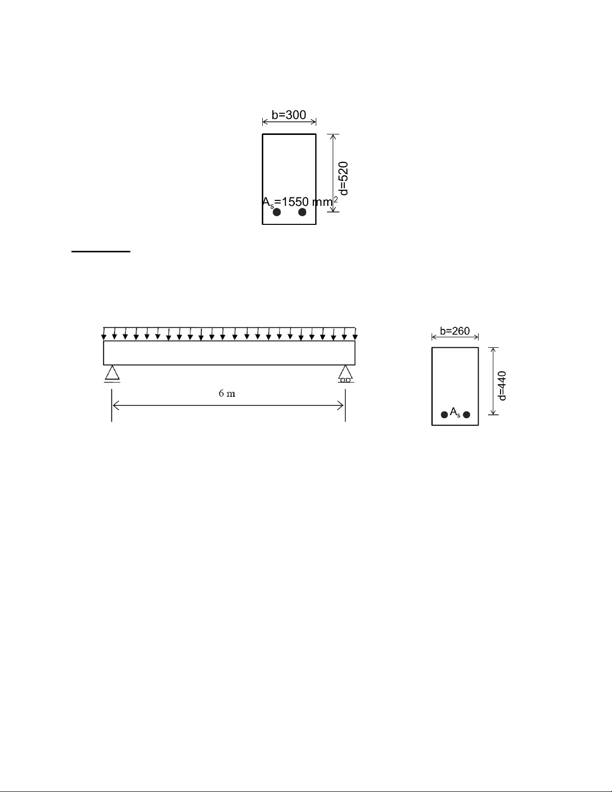
Determine the ultimate moment of resistance of the section. Given the characteristic material
strength fyk=500N/mm2 and fck=25N/mm2 Question 6:
Design a simply supported beam as shown in the figures. The beam supports uniform permanent
and variable actions of 14.0 kN/m and 15 kN/m respectively. Given the characteristic material
strength fyk=500N/mm2 and fck=25N/mm2
Tài liệu liên quan:
-
Facility Layout - Distribution Center Optimization Analysis | Môn Econometrics with Financial Application - Trường Đại học Quốc tế, Đại học Quốc gia Thành phố Hồ Chí Minh
94 47 -
Đề thi giữa kỳ học phần Engineering Drawing | Trường Đại học Quốc tế, Đại học Quốc gia Thành phố Hồ Chí Minh
275 138 -
Đề thi cuối kỳ học phần Engineering Drawing | Trường Đại học Quốc tế, Đại học Quốc gia Thành phố Hồ Chí Minh
296 148