A novel acoustic reflection principle for developing tactile sensors integrated with catheters for cardiac ablation môn Vật lý đại cương 2 | Học viện Công Nghệ Bưu Chính Viễn Thông
Abstract—Cardiac ablation is a commonly employed procedurefor treating arrhythmias, but the absence of tactile feedback increases the risk of tissue trauma . Tài liệu giúp bạn tham khảo, ôn tập và đạt kết quả cao. Mời đọc đón xem!
Môn: Vật lý đại cương 2 298 tài liệu
Trường: Học viện Công Nghệ Bưu Chính Viễn Thông 1.7 K tài liệu
Tác giả:


Preview text:
A Novel Acoustic Reflection Principle for
Developing Tactile Sensors Integrated with Catheters for Cardiac Ablation Ly Hoang Hiep* Mac Thi Thoa
School of Mechanical Engineering (HUST)
School of Mechanical Engineering (HUST) Hanoi, Vietnam Hanoi, Vietnam hiep.lyhoang@hust.edu.vn thoa.macthi@hust.edu.vn
Abstract—Cardiac ablation is a commonly employed procedure
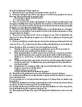
Cardiac ablation is a minimally invasive procedure in which
for treating arrhythmias, but the absence of tactile feedback
a long, thin catheter is inserted into the left or right cardiac
increases the risk of tissue trauma. To address this challenge,
chamber through the femoral vein, as shown in Fig. 1. The
integrating tactile sensors with catheters allows for safer opera-
catheter tip includes electrodes utilized to locate abnormal
tions. However, cardiac catheterization necessitates a miniature
tactile sensor with appropriate surgical properties. In this study,
tissue on the heart wall (the cause of AF) for the ablation
a novel acoustic reflection principle for developing a miniature
process. The identified ablation points are then removed using
tactile sensor is proposed to be integrated with sensorized
radiofrequency (RF) energy generated from the catheter tip,
catheters in cardiac ablation procedures. The principle involves
helping to restore normal heart rhythm [8]–[12]. Cardiac
utilizing a sinusoidal acoustic wave within an acoustic cavity
comprising rigid and elastic components. When force is applied,
the acoustic wave interacts with the elastic component, resulting
in a measurable change in the reflected wave. Theoretical analyses
were conducted to evaluate the acoustic wave’s response to
variations in the size of the sound tube. The analysis results
aided in selecting an appropriate sound frequency for the tactile
sensor’s design. A prototype sensor was developed based on
this principle, featuring a sensor tip with an acoustic cavity,
a silicone tube, and an acoustic housing containing a speaker
and a microphone. Experimental results demonstrated a direct
relationship between the sensor output and the applied force.
With a diameter of 3 mm, the developed sensor exhibits clinical
applicability and can measure contact force within the range of 0-
1 N, making it a promising tool to minimize faulty pathways and
reduce heart tissue damage during cardiac ablation procedures.
Index Terms—Cardiac ablation, tactile sensor, acoustic reflec-
tion principle, minimally invasive surgery I. INTRODUCTION
Cardiac Arrhythmia (CA) is characterized by irregular heart-
beats, which can be too fast or too slow, affecting the blood Fig. 1. Cardiac Ablation.
pressure. Some types of CA typically do not significantly
threaten human health. However, other forms of CA can lead
ablation offers many benefits to patients, such as less pain,
to serious heart-related conditions in patients, such as stroke,
quick recovery, and better domestic healing, compared to
vitium cordis, and even sudden cardiac death [1], [2]. Atrial
traditional open surgery, [12]–[14]. However, this procedure
fibrillation (AF) is the most common CA, affecting millions
still presents some challenges that need to be addressed. One
of people and showing an increasing trend yearly [3]–[7]. The
major challenge of cardiac ablation is the precise positioning
use of medications is a common treatment method to manage
of the catheter because doctors lack visual information during
the ablation process [15]. Therefore, the success of the surgery
AF. However, this approach is usually suitable for mild cases,
relies heavily on the surgeon’s skills and the accuracy of the
while severe cases may require surgical or interventional
contact between the catheter tip and cardiac tissue [16].
procedures. Cardiac ablation is a popular procedure for AF
The use of image technologies is a common approach
management recently [8]–[10].
to increase the accuracy of the catheterization procedure.
Magnetic resonance imaging (MRI) is a widely used method * Corresponding author
for real-time tracking of the catheter tip’s position during the
using the acoustic reflection principle will be developed, and
operation [17]–[20]. This method provides highly accurate
an experiment will be conducted to evaluate the responses of
images; however, the electromagnetic waves from MRI can the sensor’s output.
interfere with the catheter’s signals. Using computed tomog-
raphy (CT) is an alternative option for guiding the catheter II. MATERIALS AND METHODS
tip. However, radiation in this method can adversely affect
A. Acoustic reflection principle
both the patient and the doctor, so it is not commonly used
1) Principle: Fig. 2 illustrates an acoustic reflection princi-
[21]. Additionally, Intracardiac Echocardiography (ICE) and
ple that is used to develop a tactile sensor for cardiac ablation.
X-ray fluoroscopy [22], [23] are two techniques also used in
In this principle, a single-frequency acoustic wave generated
cardiac catheterization. Although these image technologies can
by a speaker is inserted into an acoustic cavity. The acoustic
provide relatively accurate information about the catheter tip’s
cavity comprises a rigid component and an elastic component.
position, the force contact information with these techniques
The elastic component covers the distal end of the acoustic is limited.
cavity. The acoustic wave propagates into the acoustic cavity
The force/tactile information plays a crucial role in ensuring
and reflects at the distal end (elastic component). When a force
the quality of ablation [24]–[32]. With adequate contact force
is applied to the elastic components, local deformation occurs,
between the heart tissue and the catheter, RF energy can be
leading to the distortion of the acoustic wave. A microphone
delivered more effectively, leading to a more successful abla-
can continuously capture the acoustic wave within the cavity.
tion process [15]. Furthermore, The force/tactile information
The applied force on the elastic components can be measured
also helps ensure safety by avoiding damage to the heart or
by analyzing the collected acoustic wave.
blood vessels due to excessive force from the catheter tip [33].
Some force and tactile sensors have been developed for
cardiac catheters based on piezoresistive [14], [34]–[38], mag-
netic [39], piezoelectric [40]–[42], and capacitive technologies
[43]. While these sensors can provide highly accurate force
information, the electrical components of sensors located at
the catheter tip area can pose a risk to the patient’s heart
if they leak current. Furthermore, the sterilization capability
of these sensor types remains a challenge when considering
practical usage. Fiber-optic-based force/tactile sensors [19],
[44] can address these challenges because they lack electrical
Fig. 2. Acoustic reflection principle.
components at the sensor tip. Therefore, these sensors do not
have a risk of electrical leakage to the patient and can be
In the acoustic principle depicted in Fig. 2, assuming we
effectively sterilized. However, the manufacturing cost of such
have an input wave (yin) inserted into the cavity with a sensors is relatively high.
frequency of fin and an amplitude of Ain, with a phase angle
In previous research, Tanaka et al. proposed an acoustic
of 0, and its time-domain waveform represented as follows,
reflection principle for the development of tactile sensors in
minimally invasive surgery [45]. Contact force could be deter- yin =Ainsin(2πfint)(1)
mined using acoustic wave estimation. Tactile sensors devel-
The sound wave will reflect at the elastic component, and
oped based on this principle do not have electrical components
the reflection wave yref can be expressed by the following
at the sensor tip, offering advantages such as electrical safety equation,
for human tissue and sterilizability. Additionally, acoustic-
based sensors can be fabricated at a lower cost. Several tactile
yref =rAinsin(2πfin(t−2(L−∆L) v)(2)
sensors for tumor detection and tissue softness measurement
in minimally invasive surgery (MIS) were developed based
where Lis the length of the acoustic tube, ∆Lis the height
on the acoustic principle [45]–[48]. However, in the proposed
of the local deformation, vis the speed of sound in the air
acoustic principle, the sensing area is not located at the distal
340m/s, and r(0 ≤r≤1) is the absorption coefficient of the
end of the acoustic cavity. Designing the sensing components sound wave in the cavity.
at the sensor tip is challenging, which poses a difficulty in
The output wave measured by the microphone yout is
developing small tactile sensors for cardiac catheterization.
the superposition of the input wave and the reflection wave
In this study, a novel acoustic reflection principle is pro-
according to the following equation,
posed for developing a tactile sensor for cardiac ablation. With
this principle, the sensing component will be located at the yout =yin +yref (3)
tip of the tactile sensor, allowing for a significant reduction
Assuming the formula for yout in the time domain is repre-
in the sensor’s size to make it suitable for catheterization. A sented as follows,
preliminary investigation will be conducted to assess the pro-
posed principle. A tactile sensor prototype for cardiac ablation yout =Aoutsin(2πfint+ Φ) (4)
Where Aout is the amplitude of the output wave, and Φis the
phase angle of the output wave. Aout is calculated based on
equations (1), (2), (3), and (4) as follows, A
in(r2+ 1 + 2rcos 4πfin(L−∆L) 2out =A2 v)(5)
In the principle, obtaining information about the amplitude
will be more convenient for signal processing. Therefore, only
the amplitude Aout is considered in this study to estimate the applied force.
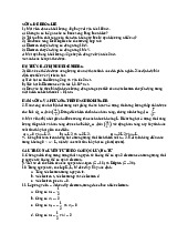
2) Preliminary analysis: The change in the sensor output
signal will be influenced by the parameters in Eq. (5). How-
ever, some parameters will remain fixed and constrained within
a certain range due to the characteristics of the sensor. Here,
the length Lof the acoustic cavity will be fixed for each
sensor, the speed of sound in air will remain constant at v=
340 m/s, and the absorption coefficient rwill be determined
depending on the material and design of the sensor. The height
Fig. 3. Preliminary analysis of the acoustic reflection principle.
of local deformation will vary depending on the interaction
force on the elastic component, but it will also be limited due
to the small size requirement of the sensor. In this analysis,
mm and an inner diameter of 1 mm, connects the sensor tip
we will investigate the influence of local deformation and the
to the acoustic housing. A sensor prototype is fabricated, as
frequency of the input wave on the sensor output to determine
depicted in the Fig. 4c. The total length of the sensor is L=
the suitable frequency range for the sensor. The evaluation
30 cm. The sensor body and acoustic case are produced using
value, denoted as S, represents the change in the sensor
a 3D printer with photopolymer resin material. The elastic
output when local deformation occurs (due to contact force)
component is made from pourable silicone material created
compared to the state without interaction force, as expressed using a 3D-printed mold. in the following, S= (Aout ) −(Aout 2 )2 (6) Ain Ain 0≤∆L≤2 ∆L=0
Since the size of the tactile sensor for cardiac ablation
is typically around 3-4.5 mm [15], ∆Lwill be evaluated
within the range of 0 to 2 mm. The length of the acoustic
cavity L= 300 mm and an absorption coefficient r= 0.7
are used in this analysis. The frequency of the input wave is
varied from fin = 0-8000 Hz. Fig. 3 illustrates the relationship
between local deformation, the frequency of the input wave,
and the evaluation value, S. A higher value of Sindicates
that the sensor output is more sensitive to changes in local
deformation at that frequency. These results show that only a
few frequencies can produce a linear change in sensor output
with respect to local deformation. The appropriate input wave
frequency can be selected based on these results B. Tactile sensor
Fig. 4. Tactile sensor. a) Design of the tactile sensor. b) Sensor tip. c) Sensor
A tactile sensor for cardiac ablation has been developed prototype.
according to the principle described above. The sensor com-
prises a sensor tip, a silicone tube, and an acoustic housing.
The sensor tip, with an outer diameter of 3 mm, comprises C. Measurement system
a sensing component (the elastic component in the proposed
Fig. 5 depicts the measurement system for the tactile sensor.
acoustic principle) and the sensor’s body, which includes an
The system comprises a tactile sensor, a sound card, and a
acoustic cavity with a diameter of 1 mm inside the sensor tip,
personal computer (PC). An input sound wave in the form of
as shown in Fig. 4. The acoustic housing contains a speaker
a sine wave with a frequency of fin = 3080 Hz is generated by
and a microphone for emitting and receiving sound waves,
a generator and the speaker, and it is inserted into the sensor.
respectively. The silicone tube, with an outer diameter of 2
The acoustic signals from the sensor are captured by the
microphone and processed through the sound card, and then
output will be collected starting from this position. The stepper
it is handled by the PC. Within the PC, the amplitude of the
motor will control the vertical stage to move downwards in
sound wave is used to estimate the contact force at the sensor.
the direction of the arrow (as shown in the figure) from the
The output obtained is processed through a digital signal
position of Z= 0 mm to the position of Z= 2 mm, with
processing system programmed within the PC. The signal is
each step being 0.5 mm. At each step, the sensor output and
smoothed using a low-pass filter with a cutoff frequency of 5
the corresponding force from the F/T sensor will be recorded.
Hz. This approach helps to eliminate any noise present in the
When the position of Z= 2 mm is reached, the vertical stage
sensor’s acoustic cavity. The processed signal is then displayed
is controlled to return to the origin. This process is repeated
in real-time on the PC screen. Based on this measurement three times to collect data.
system, an experiment will be set up to assess the feasibility B. Experimental results
of the developed sensor using the acoustic reflection principle.
Fig. 7 depicts the experimental results. Generally, the sensor
output increases as the applied force increases. The force
range of the developed tactile sensor is from 0 to 1 N. The
relationship between the sensor output and the applied force
could be represented as follows, (Y=aX2+bX +c (7) X=U−U0
where Yand Xare the estimated forces and the sensor Fig. 5. Measurement system.
output (subtraction of actual sensor output value Uand sensor
output value U0at Z= 0), respectively. The polynomial fitting III. EXPERIMENT
method with order n= 2 was used to calculate the calibration
coefficients a, b, and c. The calibration coefficients were given
A. Experimental setup and procedure
as [a, b, c] = [859.043680,26.448668,−0.015438].
Fig. 6 illustrates an experiment to test the response of
the developed tactile sensor. In this experiment, the tactile
sensor is securely mounted on a vertical stage. The vertical
stage is fixed onto a fixture plate using aluminum frames.
The movement of the vertical stage is controlled by a stepper
motor. A commercial F/T force sensor (ATI nano 17), attached
to the fixture plate, is used to measure the forces applied on the tactile sensor. Fig. 7. Experimental results. IV. DISCUSSIONS
Based on the preliminary theoretical analysis results, it
is evident that only at specific frequencies does the sensor
output provide the best signal corresponding to the changes
in local deformation (due to contact force). The theoretical
analysis suggests that the ratio between sensor output and local
deformation increases with frequency. However, a higher slope
leads to greater sensitivity to noise. Additionally, due to the
very small size of the acoustic cavity in tactile sensors, the
resonance characteristics reduce the sensor output amplitude Fig. 6. Experimental setup.
as the frequency increases [45]. Therefore, through experimen-
tation, a suitable frequency of fin = 3080 Hz can be selected,
In this experiment, initially, the tactile sensor is moved close
considering the tactile sensor’s size and design.
to the F/T sensor so that the contact force is equal to 0. At
For cardiac ablation procedures, the diameter of the catheter
this point, we define this as the origin (Z= 0 mm). The sensor
tip is typically 3.5-4 mm [15]. Therefore, with a diameter of
only 3 mm, the tactile sensor developed using the acoustic
[3] G. Hindricks et al., “2020 ESC Guidelines for the diagnosis and
reflection principle is perfectly suited for cardiac ablation.
management of atrial fibrillation developed in collaboration with the
European Association for Cardio-Thoracic Surgery (EACTS): The Task
Furthermore, the force requirements for the tactile sensor in
Force for the diagnosis and management of atrial fibrillation of the
cardiac ablation typically fall within the range of 0–0.5 N [15].
European Society of Cardiology (ESC) Developed with the special
With a force range of 0–1 N, the tactile sensor can fully meet
contribution of the European Heart Rhythm Association (EHRA) of
the ESC,” Eur. Heart J., vol. 42, no. 5, pp. 373–498, 2021, doi:
the force working range requirements while ensuring that the 10.1093/eurheartj/ehaa612.
sensor does not become overloaded. Additionally, the 5 Hz
[4] G. Y. H. Lip et al., “Atrial fibrillation,” Nat. Rev. Dis. Primers, vol. 2,
filter currently used for the sensor can adequately satisfy the
no. 1, 2016, doi: 10.1038/nrdp.2016.16.
sensor’s operating bandwidth requirement of 2 Hz [15].
[5] S. S. Chugh et al., “Worldwide epidemiology of atrial fibrillation: A
Global Burden of Disease 2010 study,” Circulation, vol. 129, no. 8, pp.
Although the initial theoretical analysis and experiments
837–847, 2014, doi: 10.1161/circulationaha.113.005119.
have yielded promising results regarding the feasibility of the
[6] G. Lippi, F. Sanchis-Gomar, and G. Cervellin, “Global epidemiol-
acoustic reflection principle and the tactile sensor prototype
ogy of atrial fibrillation: An increasing epidemic and public health
challenge,” Int. J. Stroke, vol. 16, no. 2, pp. 217–221, 2021, doi:
for cardiac ablation, some areas still need improvement in the 10.1177/1747493019897870.
future. Regarding theoretical foundations, the length Land
[7] E. Kodani and H. Atarashi, “Prevalence of atrial fibrillation in Asia
absorption coefficient rare currently held constant for the pre-
and the world,” J. Arrhythm., vol. 28, no. 6, pp. 330–337, 2012, doi: 10.1016/j.joa.2012.07.001.
liminary assessment of the proposed acoustic principle. These
[8] S. Dokos, Modelling organs, tissues, cells and devices. Berlin, Heidel-
parameters will be varied in future research to observe the
berg: Springer Berlin Heidelberg, 2017.
sensor’s response. Furthermore, other factors, such as cavity
[9] P. Polygerinos, D. Zbyszewski, T. Schaeffter, R. Razavi, L. D. Senevi-
ratne, and K. Althoefer, “MRI-compatible fiber-optic force sensors
size or sensor material, will be investigated to optimize the
for catheterization procedures,” IEEE Sens. J., vol. 10, no. 10, pp.
principle. Regarding the sensor, the current length L= 30 cm is
1598–1608, 2010, doi: 10.1109/jsen.2010.2043732.
relatively short for a cardiac ablation procedure. In the future,
[10] H. W. Cao, “Irrigated ablation catheter having a pressure sensor to detect
we will develop a longer sensor with higher applicability for
tissue contact,” Sep. 22, 2009
[11] P. Polygerinos, A. Ataollahi, T. Schaeffter, R. Razavi, L. D. Seneviratne,
actual cardiac ablation procedures. Additionally, experiments
and K. Althoefer, “MRI-compatible intensity-modulated force sensor for
involving the application of the sensor to actual tissue will be
cardiac catheterization procedures,” IEEE Trans. Biomed. Eng., vol. 58,
conducted in further work to evaluate the effectiveness of the
no. 3, pp. 721–726, 2011, doi: 10.1109/TBME.2010.2095853.
[12] A. L. Trejos, R. V. Patel, and M. D. Naish, “Force sensing and its developed sensor.
application in minimally invasive surgery and therapy: A survey,” Proc
Inst Mech Eng Part C, vol. 224, no. 7, pp. 1435–1454, 2010, doi: 10.1243/09544062jmes1917. V. CONCLUSIONS
[13] G. S. Guthart and J. K. Salisbury, “The Intuitive/sup TM/ telesurgery
system: overview and application,” in Proceedings 2000 ICRA. Mil-
This study proposes a novel acoustic reflection principle
lennium Conference. IEEE International Conference on Robotics and
for developing a tactile sensor for cardiac ablation. In this
Automation. Symposia Proceedings (Cat. No.00CH37065), IEEE, 2002.
principle, the sensing area is located at the distal end of the
[14] P. Puangmali, K. Althoefer, L. D. Seneviratne, D. Murphy, and P.
Dasgupta, “State-of-the-art in force and tactile sensing for minimally
acoustic cavity, which minimizes the tactile sensor’s size. The
invasive surgery,” IEEE Sens. J., vol. 8, no. 4, pp. 371–381, 2008, doi:
preliminary theoretical analysis showed that only several fre- 10.1109/jsen.2008.917481.
quencies could provide a strong sensor output when the contact [15] V. S. N. Sitaramgupta, D. Padmanabhan, P. S. M. Rao, and H. J.
Pandya, “Force sensing technologies for catheter ablation procedures,”
force is applied to the sensing area of the acoustic cavity. The
Mechatronics (Oxf.), vol. 64, no. 102295, p. 102295, 2019, doi:
tactile sensor was developed based on the proposed acoustic
10.1016/j.mechatronics.2019.102295.
principle. The sensor is made of biocompatible materials and
[16] K. Yokoyama et al., “Novel contact force sensor incorporated in irrigated
radiofrequency ablation catheter predicts lesion size and incidence of
has advantages in medical environments, such as electrical
steam pop and thrombus,” Circ. Arrhythm. Electrophysiol., vol. 1, no.
safety and sterilization. Moreover, the sensor is small enough
5, pp. 354–362, 2008, doi: 10.1161/CIRCEP.108.803650.
(diameter of 3 mm) for catheterization. Experimental results
[17] S. R. Dukkipati et al., “Electroanatomic mapping of the left ventricle
in a porcine model of chronic myocardial infarction with magnetic
demonstrated that the sensor output increases with the applied
resonance-based catheter tracking,” Circulation, vol. 118, no. 8, pp.
force and that the force range is sufficient for cardiac ablation
853–862, 2008, doi: 10.1161/CIRCULATIONAHA.107.738229.
procedures. The tactile sensor’s structure will be improved
[18] P. Polygerinos, L. D. Seneviratne, R. Razavi, T. Schaeffter, and K.
to optimize the sensor output response in future work. Fur-
Althoefer, “Triaxial catheter-tip force sensor for MRI-guided cardiac
procedures,” IEEE ASME Trans. Mechatron., vol. 18, no. 1, pp.
thermore, practical experiments involving actual tissue will be
386–396, 2013, doi: 10.1109/tmech.2011.2181405.
conducted to evaluate the effectiveness of the tactile sensor
[19] P. Nordbeck et al., “Cardiac catheter ablation under real-time magnetic
using the acoustic principle for cardiac ablation and other
resonance guidance,” Eur. Heart J., vol. 33, no. 15, pp. 1977–1977, 2012, doi: 10.1093/eurheartj/ehs139. medical procedures.
[20] P. Polygerinos, P. Puangmali, T. Schaeffter, R. Razavi, L. D. Seneviratne,
and K. Althoefer, “Novel miniature MRI-compatible fiber-optic force
sensor for cardiac catheterization procedures,” in 2010 IEEE Interna- REFERENCES
tional Conference on Robotics and Automation, IEEE, 2010.
[21] R. D. Nawfel, P. F. Judy, S. G. Silverman, S. Hooton, K. Tuncali, and
[1] J. Klingelh¨ofer and D. Sander, “Cardiovascular consequences of clinical
D. F. Adams, “Patient and personnel exposure during CT fluoroscopy-
stroke,” Baillieres. Clin. Neurol., vol. 6, no. 2, pp. 309–335, 1997.
guided interventional procedures,” Radiology, vol. 216, no. 1, pp.
[2] P. S¨or¨os and V. Hachinski, “Cardiovascular and neurological causes of
180–184, 2000, doi: 10.1148/radiology.216.1.r00jl39180.
sudden death after ischaemic stroke,” Lancet Neurol., vol. 11, no. 2, pp.
[22] F. Schiele et al., “Intravascular ultrasound–guided balloon angioplasty
179–188, 2012, doi: 10.1016/S1474-4422(11)70291-5.
compared with Stent: Immediate and 6-month results of the multicenter,
randomized Balloon Equivalent to Stent study (BEST),” Circulation, vol.
sive Ther. Allied Technol., vol. 19, no. 1, pp. 52–60, 2010, doi:
107, no. 4, pp. 545–551, 2003, doi: 10.1161/01.cir.0000047212.94399.7e 10.3109/13645700903516742.
[23] Y. Khaykin et al., “Intracardiac ECHO integration with three dimen-
[43] J. A. Dobrzynska and M. A. M. Gijs, “Polymer-based flexible capacitive
sional mapping: Role in AF ablation,” J. Atr. Fibrillation, vol. 1, no. 2,
sensor for three-axial force measurements,” J. Micromech. Microeng.,
p. 32, 2008, doi: 10.4022/jafib.32.
vol. 23, no. 1, p. 015009, 2013, doi: 10.1088/0960-1317/23/1/015009.
[24] Catheter ablation of cardiac arrhythmias. Elsevier, 2011.
[44] H. Su et al., “Fiber-optic force sensors for MRI-guided interventions and
[25] K. Yokoyama et al., “Novel contact force sensor incorporated in irrigated
rehabilitation: A review,” IEEE Sens. J., vol. 17, no. 7, pp. 1952–1963,
radiofrequency ablation catheter predicts lesion size and incidence of
2017, doi: 10.1109/jsen.2017.2654489.
steam pop and thrombus,” Circ. Arrhythm. Electrophysiol., vol. 1, no.
[45] Y. Tanaka, T. Fukuda, M. Fujiwara, and A. Sano, “Tactile sensor using
5, pp. 354–362, 2008, doi: 10.1161/circep.108.803650.
acoustic reflection for lump detection in laparoscopic surgery,” Int. J.
[26] Z. Issa and J. M. Miller, Clinical arrhythmology and electrophysiology:
Comput. Assist. Radiol. Surg., vol. 10, no. 2, pp. 183–193, 2015, doi:
A companion to braunwald’s heart disease, 2nd ed. London, England: 10.1007/s11548-014-1067-z. W B Saunders, 2012.
[46] H. H. Ly, Y. Tanaka, and M. Fujiwara, “A tactile sensor using the
[27] Y. Okumura, S. B. Johnson, T. J. Bunch, B. D. Henz, C. J. O’brien,
acoustic reflection principle for assessing the contact force component in
and D. L. Packer, “A systematical analysis ofin vivocontact forces on
laparoscopic tumor localization,” Int. J. Comput. Assist. Radiol. Surg.,
virtual catheter tip/tissue surface contact during cardiac mapping and
vol. 16, no. 2, pp. 289–299, 2021, doi: 10.1007/s11548-020-02294-w.
intervention,” J. Cardiovasc. Electrophysiol., vol. 19, no. 6, pp. 632–640,
[47] H. H. Ly, Y. Tanaka, T. Fukuda, and A. Sano, “Grasper having tactile
2008, doi: 10.1111/j.1540-8167.2008.01135.x.
sensing function using acoustic reflection for laparoscopic surgery,” Int.
[28] T. Lin, F. Ouyang, K.-H. Kuck, and R. Tilz, “ThermoCool® Smart-
J. Comput. Assist. Radiol. Surg., vol. 12, no. 8, pp. 1333–1343, 2017,
Touch® Catheter – the evidence so far for contact force technology and
doi: 10.1007/s11548-017-1592-7.
the role of VisiTag module,” Arrhythm. Electrophysiol. Rev., vol. 3, no.
[48] T. Ukai, Y. Tanaka, T. Fukuda, T. Kajikawa, H. Miura, and Y. Terada,
1, pp. 44–47, 2014, doi: 10.15420/aer.2011.3.1.44.
“Softness sensing probe with multiple acoustic paths for laparoscopic
[29] A. Thiagalingam et al., “Importance of catheter contact force during
surgery,” Int. J. Comput. Assist. Radiol. Surg., vol. 15, no. 9, pp.
irrigated radiofrequency ablation: Evaluation in a porcineex vivomodel
1537–1547, 2020, doi: 10.1007/s11548-020-02207-x.
using a force-sensing catheter,” J. Cardiovasc. Electrophysiol., 2010, doi:
10.1111/j.1540-8167.2009.01693.x.
[30] H. J. Pandya, J. Sheng, and J. P. Desai, “Towards a tri-axial flexible
force sensor for catheter contact force measurement,” in 2016 IEEE SENSORS, IEEE, 2016.
[31] L. Di Biase et al., “Visual, tactile, and contact force feedback: Which
one is more important for catheter ablation? Results from an in vitro
experimental study,” Heart Rhythm, vol. 11, no. 3, pp. 506–513, 2014,
doi: 10.1016/j.hrthm.2013.11.016.
[32] H. J. Pandya, K. Park, and J. P. Desai, “Design and fabrication of a
flexible MEMS-based electro-mechanical sensor array for breast cancer
diagnosis,” J. Micromech. Microeng., vol. 25, no. 7, p. 075025, 2015,
doi: 10.1088/0960-1317/25/7/075025.
[33] S. W. Hetts et al., “Endovascular catheter for magnetic navigation
under MR imaging guidance: evaluation of safety in vivo at 1.5T,”
AJNR Am. J. Neuroradiol., vol. 34, no. 11, pp. 2083–2091, 2013, doi: 10.3174/ajnr.A3530.
[34] B. Han, Y.-J. Yoon, M. Hamidullah, A. T.-H. Lin, and W.-T. Park,
“Silicon nanowire-based ring-shaped tri-axial force sensor for smart
integration on guidewire,” J. Micromech. Microeng., vol. 24, no. 6, p.
065002, 2014, doi: 10.1088/0960-1317/24/6/065002.
[35] J. Rad ´ o et al., “3D force sensors for laparoscopic surgery tool,”
Microsyst. Technol., vol. 24, no. 1, pp. 519–525, 2018, doi: 10.1007/s00542-017-3443-4.
[36] L. Beccai et al., “Design and fabrication of a hybrid silicon three-axial
force sensor for biomechanical applications,” Sens. Actuators A Phys.,
vol. 120, no. 2, pp. 370–382, 2005, doi: 10.1016/j.sna.2005.01.007.
[37] N. Thanh-Vinh, N. Binh-Khiem, H. Takahashi, K. Matsumoto, and I.
Shimoyama, “High-sensitivity triaxial tactile sensor with elastic mi-
crostructures pressing on piezoresistive cantilevers,” Sens. Actuators A
Phys., vol. 215, pp. 167–175, 2014, doi: 10.1016/j.sna.2013.09.002.
[38] P. Valdastri et al., “Miniaturized cutting tool with triaxial force sensing
capabilities for minimally invasive surgery,” J. Med. Device., vol. 1, no.
3, pp. 206–211, 2007, doi: 10.1115/1.2778700.
[39] H. Nakagawa et al., “Locations of high contact force during left
atrial mapping in atrial fibrillation patients: Electrogram amplitude and
impedance are poor predictors of electrode-tissue contact force for
ablation of atrial fibrillation,” Circ. Arrhythm. Electrophysiol., vol. 6,
no. 4, pp. 746–753, 2013, doi: 10.1161/circep.113.978320.
[40] C. Chi, X. Sun, N. Xue, T. Li, and C. Liu, “Recent progress in
technologies for tactile sensors,” Sensors (Basel), vol. 18, no. 4, p. 948, 2018, doi: 10.3390/s18040948.
[41] M. Kalantari, M. Ramezanifard, R. Ahmadi, J. Dargahi, and J.
K¨ovecses, “A piezoresistive tactile sensor for tissue characterization
during catheter-based cardiac surgery: Tactile sensor for catheter-based
technique,” Int. J. Med. Robot., vol. 7, no. 4, pp. 431–440, 2011, doi: 10.1002/rcs.413.
[42] H. Wang, P. X. Liu, S. Guo, and X. Ye, “A catheter side wall
tactile sensor: Design, modeling and experiments,” Minim. Inva-
Tài liệu liên quan:
-
Bài tập Vật lý nguyên tử môn Vật lý đại cương 2 | Học viện Công Nghệ Bưu Chính Viễn Thông
11 6 -
Bài tập Vật lý nguyên tử môn Vật lý đại cương 2 | Học viện Công Nghệ Bưu Chính Viễn Thông
12 6 -

Tán xạ ánh sáng và Hiệu ứng Tyndall - Lý thuyết và Ứng dụng môn Vật lý đại cương 2 | Học viện Công Nghệ Bưu Chính Viễn Thông
19 10 -

Chương 23: Quang học lượng tử môn Vật lý đại cương 2 | Học viện Công Nghệ Bưu Chính Viễn Thông
17 9 -

Chương 24: Cơ Học Lượng Tử - Tính Sóng-Hạt và Phương Trình Schrödinger môn Vật lý đại cương 2 | Học viện Công Nghệ Bưu Chính Viễn Thông
18 9