áo cáo thí nghiệm 3: động lực và dao động tự do trong mạch rlc môn Vật lý đại cương 2 | Học viện Công Nghệ Bưu Chính Viễn Thông
Understanding the current across an inductor-resistor and RLCcircuit.- Calculating the energy of the oscillation RLC circuit . Tài liệu giúp bạn tham khảo, ôn tập và đạt kết quả cao. Mời đọc đón xem!
Môn: Vật lý đại cương 2 298 tài liệu
Trường: Học viện Công Nghệ Bưu Chính Viễn Thông 1.7 K tài liệu
Tác giả:


Preview text:
Experimental Report 3:
INDUCTOR AND FREE OSCILLATION IN RLC CIRCUIT
Verification of the instructors
Class: CTTT Cơ Điện Tử 03 - K69 Group: 03 Name: Phạm Thanh Lâm Student ID: 202418502 I.
Experimental motivations
- Understanding the current across an inductor-resistor and RLC circuit.
- Calculating the energy of the oscillation RLC circuit. II. Experimental result
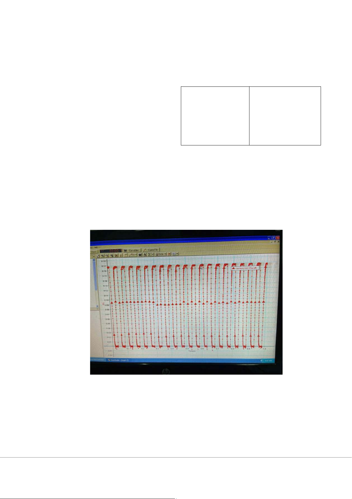
Part 1: Resistance and Inductance of the coil Without core Image of the Current I 0 = 0.17 (A)
Image of the Voltage VS = 0.93 (V) Image of the Slope S = -707 The Vs
resistance of the coil: RL = Io =0.93 = 5.49 (Ω) 0.17 Vs Coil 0.93 inductance : Lw= = =7.76 x 10⁻³(H) Io ×S 0.17×707
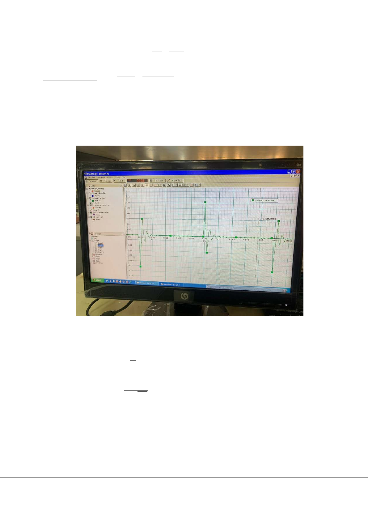
Part 2: Free oscillation of the RLC circuit 1. Frequency: The current in RLC circuit
T = 0.18 x 10⁻² (s) Lw= 7.76 x 10⁻³(H) C = 10 x 10-6 (F) 1
⇨f experimental = T = 556 (Hz)
The frequency based on theoretical calculation: 1
⇨ftheorotical= 2π √LC = 571 (Hz) ∆ f=15.00(Hz) 2. Energy
C = 10µF L = 7.76mH I = 0.17A V=0.93V
-We can find the graph of energy of each oscillation in the capacitance and
the inductance and then the energy 1 Uc = CV2 =4.32 x 10⁻⁴ J 2 1 UL LI = 2 = 1.12 x 10⁻³ J 2 The 1 1
total energy: U = Uc + UL CV2 + LI = 2 = 1.55 x 10⁻³ J 2 2
-By combining the previous graphs, we have the graph present the energy in an RLC circuit: +Comment:
● After stopping the electric power, the energy of the circuit does not
decrease rapidly to zero, it reduces to zero over a short period of time.
● The energy of oscillations of the coil and the capacitor are damped oscillations. +Explain:
● The energy of the circuit loses by the heat of the resistor at rate i2R
● The graph of total energy is steepest at the time that the magnetic
energy reaches a local maximum because in these times, the current
through the coil is highest, and the loss of energy is mainly due to the
resistance of the coil (ΔQ=i2R).
Tài liệu liên quan:
-
Bài tập Vật lý nguyên tử môn Vật lý đại cương 2 | Học viện Công Nghệ Bưu Chính Viễn Thông
11 6 -
Bài tập Vật lý nguyên tử môn Vật lý đại cương 2 | Học viện Công Nghệ Bưu Chính Viễn Thông
11 6 -

Tán xạ ánh sáng và Hiệu ứng Tyndall - Lý thuyết và Ứng dụng môn Vật lý đại cương 2 | Học viện Công Nghệ Bưu Chính Viễn Thông
19 10 -

Chương 23: Quang học lượng tử môn Vật lý đại cương 2 | Học viện Công Nghệ Bưu Chính Viễn Thông
17 9 -

Chương 24: Cơ Học Lượng Tử - Tính Sóng-Hạt và Phương Trình Schrödinger môn Vật lý đại cương 2 | Học viện Công Nghệ Bưu Chính Viễn Thông
18 9