Báo cáo Thí Nghiệm 5: Nghiên Cứu Truyền Sóng Điện Từ môn Vật lý đại cương 2 | Học viện Công Nghệ Bưu Chính Viễn Thông
Evaluate both qualitative and quantitative results of transmitting andreceiving microwave . Tài liệu giúp bạn tham khảo, ôn tập và đạt kết quả cao. Mời đọc đón xem!
Môn: Vật lý đại cương 2 298 tài liệu
Trường: Học viện Công Nghệ Bưu Chính Viễn Thông 1.7 K tài liệu
Tác giả:


Preview text:
Experimental Report 5
INVESTIGATION OF TRANSMISSION OF ELECTROMAGNETIC WAVE (MICROWAVE)
Verification of the instructors
Class: CTTT Cơ Điện Tử 03-K69 Group: 3
Name: Phạm Thanh Lâm
Student ID: 202418502
I. Experiment Motivation
●Evaluate both qualitative and quantitative results of transmitting and receiving microwave.
II. Experimental Results
1. Investigation of straight-line propagation of microwaves Observation:
● When the receiver is aligned with the rail (the transmitter and receiver are
facing each other), the volt-meter shows the maximum value.
● When the receiver moves far from the rail (in a plane perpendicular to the rail),
the value of volt-meter decreases. Conclusion:
●Microwaves propagate best in a straight line.
2. Investigation of penetration of microwaves Observation:
●When a dry absorption plate (electrical insulator) is put between transmitter
and receiver, the volt-meter slightly decrease Conclusion:
● Microwaves can penetrate through the dry absorption plate.
● Not all of the microwave will penetrate through the dry absorption plate, a part
of them will be absorbed by the absorption plate.
3. Investigation of screening and absorption of microwaves Observation:
●When a reflection plate (electrical conductor) is put between transmitter and
receiver, the volt-meter shows a value that is very small compared to the value
when the absorb plate is absent. In this case, the volt-meter shows a value approximately 0 (0.01). Conclusion:
●Most microwaves will not go through the reflection plate.
4. Investigation of reflection of microwaves Observation: Reflector angle (o) Incidence angle (o) 30 45 40 42 50 57 60 41
●When the arrow is the bisector of 2 rails (the reflector angle is equal to the
incidence angle), the volt-meter shows maximum value. Conclusion:
●Microwave reflects best when the perpendicular bisector of the reflection plate
is the bisector of an angle created by the transmitter and receiver.
●When the microwave reflects, the angle of incidence equals the angle of reflection.
5. Investigation of refraction of microwaves
- Let assume that the angle θ created by transmitter and receiver, then θ is called angle of deflection
- After 3 measurements, we have Trials θ (o) 1 149 2 150 3 142 Observation:
As turning the receiver to different angles, the value of the volt-meter decreases. Conclusion:
Microwave refracts best with angle of θ
6. Investigation of diffraction of microwaves Observation:
When the single slit plane is put in the rail, the value on the voltmeter increase
When the plate is between the probe and the transmitter, the value on the
voltmeter is approximate 0. When the probe is moved on the horizontal plane, the value slightly increase Conclusion:
Microwaves have diffraction properties.
7. Investigation of interference of microwaves Observation:
●When the probe is moved parallel to the plate, the value on the voltmeter is
oscillating. Number of maxima = 3
Conclusion: Microwaves have the property of interference.
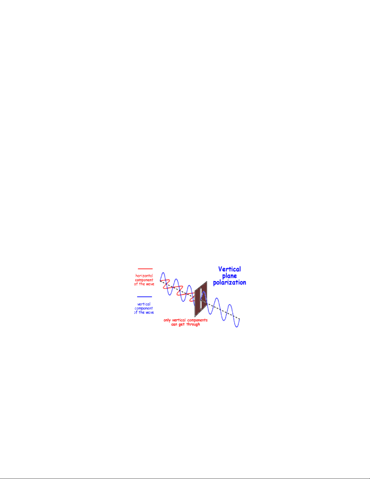
8. Investigation of polarization of microwaves Observation:
When the grating is aligned horizontally, the value on the voltmeter is slightly decreasing
When the grating is aligned vertically, the value on the voltmeter is approximately zero
When the grating is aligned at 45 o, the value on the voltmeter is higher than
vertical case, but lower than horizontal case Conclusion:
●When we put a polarization grating between transmitter and receiver, the
microwave (electromagnetic) will be polarized as shown in fig 1.
Because the vertical wave is an electric wave, and the receiver’s signal we receive is Voltage. Therefore:
●With vertical polarization grating, only the vertical wave can go through. The receiver’s signal is big.
●With horizontal polarization grating, only the horizontal wave can go through.
The receiver’s signal is very small (approximate to 0).
●With 45o inclined polarization grating, a part of the vertical wave and
horizontal wave can go through. The receiver’s signal is smaller than when we
use vertical polarization grating and bigger than when we use horizontal polarization grating.
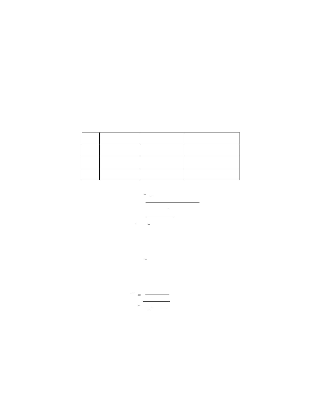
9. Determining wavelength of standing waves f x1 (mm) x2 (mm) x = x1 - x2 (mm) 1 176 155 21 2 180 160 20 3 181 160 21 3 x=13∑ xi=20.67(mm) i=1 √3∑(x¿¿i−x)2 ∆x= i=1 3=0.44(mm)¿ λ=2×x=2×20.67=41.34 (mm) ∆λ=∆x=0.44(mm) Hence λ=λ±∆ λ=41.34±0.44(mm) Frequency of the microwave: f=c λ=3×10⁸ 41.34×10−3=7.24×10⁹ (Hz)
∆ f=f √(∆λ )2+(∆c )2=0.08×10⁹(Hz) x λ c f=f ±∆f =(7.24±0.07)×109 (Hz)
Tài liệu liên quan:
-
Bài tập Vật lý nguyên tử môn Vật lý đại cương 2 | Học viện Công Nghệ Bưu Chính Viễn Thông
11 6 -
Bài tập Vật lý nguyên tử môn Vật lý đại cương 2 | Học viện Công Nghệ Bưu Chính Viễn Thông
11 6 -

Tán xạ ánh sáng và Hiệu ứng Tyndall - Lý thuyết và Ứng dụng môn Vật lý đại cương 2 | Học viện Công Nghệ Bưu Chính Viễn Thông
19 10 -

Chương 23: Quang học lượng tử môn Vật lý đại cương 2 | Học viện Công Nghệ Bưu Chính Viễn Thông
17 9 -

Chương 24: Cơ Học Lượng Tử - Tính Sóng-Hạt và Phương Trình Schrödinger môn Vật lý đại cương 2 | Học viện Công Nghệ Bưu Chính Viễn Thông
18 9