Building XOR Gate Using AND, OR, and NOT Gates | Môn Hệ thống nhúng trong công nghiệp - Đại học Sư phạm Kỹ thuật Thành phố Hồ Chí Minh
In Logisim, you can build a new circuit and give it a name. (Then you can use the circuits as components in other circuits. Tài liệu được sưu tầm gồm 7 trang, giúp bạn ôn tập tốt hơn. Mời các bạn đón xem.
Môn: Hệ thống nhúng trong công nghiệp 10 tài liệu
Trường: Trường Đại học Sư phạm Kỹ thuật Thành phố Hồ Chí Minh 4.4 K tài liệu
Tác giả:


Preview text:
lOMoAR cPSD| 58702377 Review 1: XOR gate
For this Review, you will build an XOR gate out of AND, OR, and NOT gates.
Note that Logisim already has an XOR gate, but you should build your own. (This is
essentially the "Tutorial" in the "Help" menu of the program, except that I am asking
you to give a name to the circuit that you create.)
In Logisim, you can build a new circuit and give it a name. (Then you can use
the circuits as components in other circuits. This allows you to build up complex
circuits from simpler circuits, just like you make complex programs from simpler subroutines).
To start the Review, create a new circuit, using the "Add Circuit" command
in the "Project" menu. You will be asked for a circuit name. Enter XOR as the
name of the new circuit for the first Review. The circuit that you have created is
added to the palette of circuit elements in the upper left portion of the window, under
the name of the file that you are working in (probably "Untitled" at present). To view
and edit a circuit that you have created, double-click its name in the list.
Logisim has three mouse tools, which have different functions. They are shown
as icons on the left end of the toolbar. The right end of the toolbar shows five
common circuit elements, input, output, NOT gate, AND gate, and OR gate:
The "poke" tool, which looks like a pointing hand, is for poking inputs to turn them
on and off. You can also poke a wire to see the value on that wire. The "edit/select"
tool, which looks like an arrow, allows you to add components to a circuit and to
select existing elements in the circuit; this is the default tool. The "text" tool, which
looks like an "A", is used to add strings of text to a circuit; just click with the text
tool, and type something. Click existing text with the text tool to edit it. You can also
click a component such as an input or output to add a label to that component.
Use the arrow tool to edit the circuit. To add a component to the circuit that you
are editing, click the component in the toolbar or in the palette of circuit elements
(with the arrow tool). Move the mouse to the place where you want to place the
component and click again. (Do not drag the component. Click it and release the
mouse, move the mouse, and click again.) For example, to add an AND gate, click
the AND gate in the toolbar or in the component palette, move to the position where
you want the AND gate, and click again. lOMoAR cPSD| 58702377
The arrow tool is also used to add wires to the circuit. When the arrow tool is
over a point where you can start drawing a wire, Logisim draws a small green circle
around that point. Click and drag to draw the wire. In general, things that look like
they are connected are in fact connected. (If you click a wire and release the mouse
without dragging, the wire is selected. You can then drag the wire as a whole.)
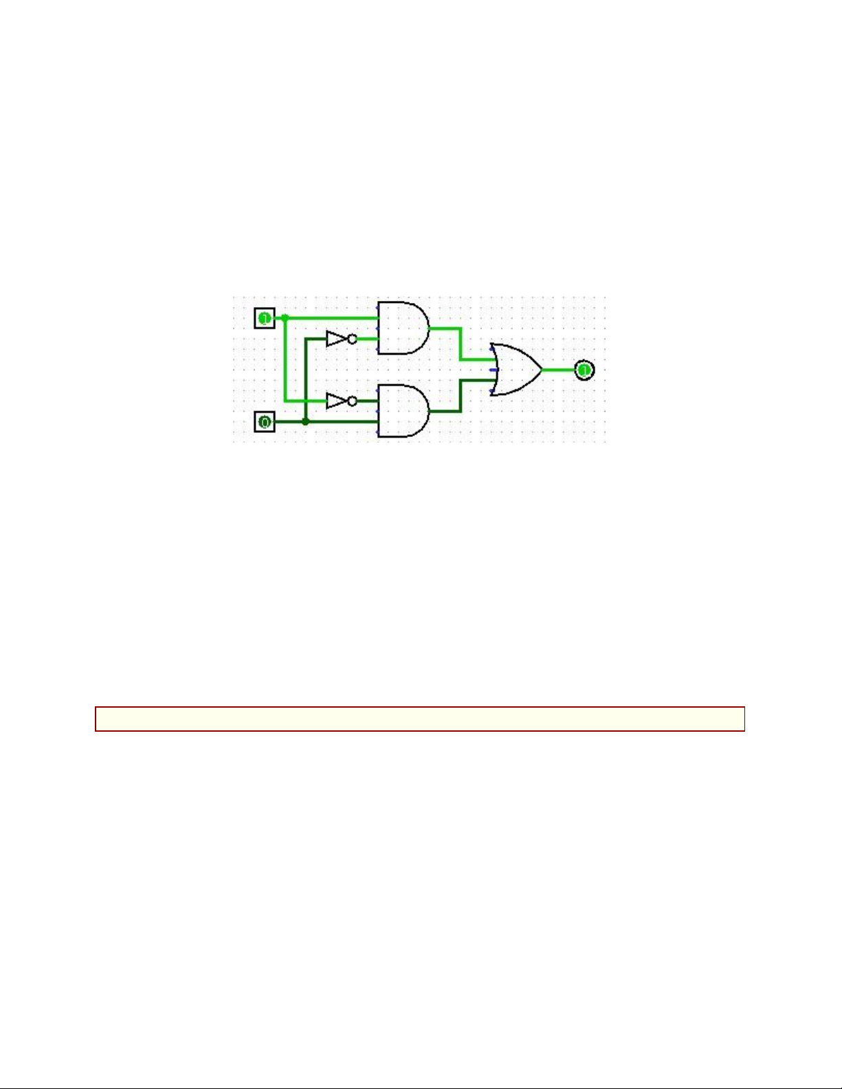
There are several ways to make an XOR circuit from AND, OR, and NOT gates.
If the inputs are A and B, then A XOR B can be computed as (A & ~B) | (B &
~A) You should build an XOR circuit following this formula. it will look like this:
Test that your circuit works by using the poke tool to click the two inputs. Try all
four combinations of input, and make sure that the outputs are correct. (By default,
AND and OR gates have 5 inputs, but Logisim only bases the computation on inputs
that are actually connected to something, so extra, unconnected inputs are not a
problem. But if this bothers you, you can change the number of inputs on a gate. You
can also change its size. And remember that you can copy-and-paste gates that you
have configured to your liking.)
Q name lab4.circ. (The name of a Logisim file should end with ".circ".) You
should save your circuits frequently while you are working, and maybe even
save several versions in different files along the way.
Review 2: One-bit Adder
For the next Review, add another circuit using the "Add Circuit" command in
the "Project" menu, and name it "Add-1". You will create an adder that can add three
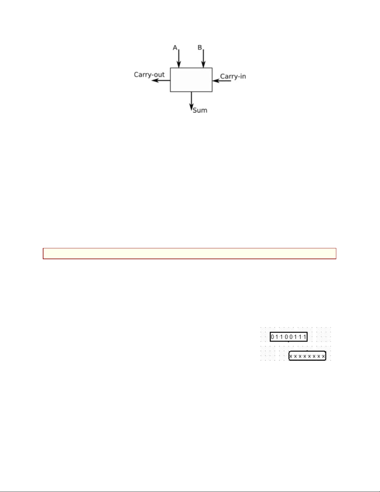
input bits (A, B, and Carry-in) and produce a Sum bit and a Carry-out bit as output. In
class, we saw how to make an adder from two half-adders. You should arrange the
inputs and outputs for the adder circuit as shown here: lOMoAR cPSD| 58702377
When building a circuit, it is the direction that an input or output pin is facing that
determines which side of the circuit it will appear on, when the circuit is used as a
sub-circuit in another circuit. Make sure that A is facing South, Carry-out is facing East, and so on.
A half-adder can use an XOR gate. In your adder, you can use either the one that
you built for Review 1 or the one that is built into Logisim. You don't necessarily
have to build a separate half-adder circuit, but you can do that if you want.
Note: Please add labels to the inputs and outputs in this circuit, and in any
non-trivial circuit that you make. It will make it easier to understand the circuit
and remember what it does.
Review 3: Eight-bit Adder
For the third Review, add another circuit to the project, using the name "Add-
8". The purpose of the circuit is to take two eight-bit numbers and a one-bit carry-in
and to produce an eight-bit sum and a one-bit carry-out as output. We saw in class
how to construct multiple-bit adders from several one-bit adders. User eight copies
of the Adder that you created for Review 2.
In Logisim, it is possible to have multi-bit inputs, multi-
bit outputs, and wires that carry multiple bits of data. To make
an eight-bit input, for example, add an input to your circuit,
then change the value of the "Data Bits" property of the input
to 8 (in the properties list in the lower left section of the window). An eight-bit input
and an eight-bit output are shown at the right. The poke tool has been used to change
the value of the input to 01100111. The values of the output bits are undefined, since
the output is not connected to anything. You should use eight-bit inputs and outputs for your adder. lOMoAR cPSD| 58702377
But you need single-bit wires to feed into your individual Adder
circuits. For that, you need a "Splitter". A Splitter splits a multi-bit
bundle of wires into smaller bundles of wires or into individual wires.
You can find "Splitter" in the "Wiring" section of the component
palette. The picture at left shows a splitter connected to
the multi-bit wire going into an 8-bit output; the splitter splits that 8-bit wire into 8
individual one-bit wires. In this case, the properties of the splitter have been set so
that it is "Facing" North, has a "Bit Width In" of 8, and a "Fan Out" of 8. Each of the
eight wires can be connected, for example, to the output from an Adder.
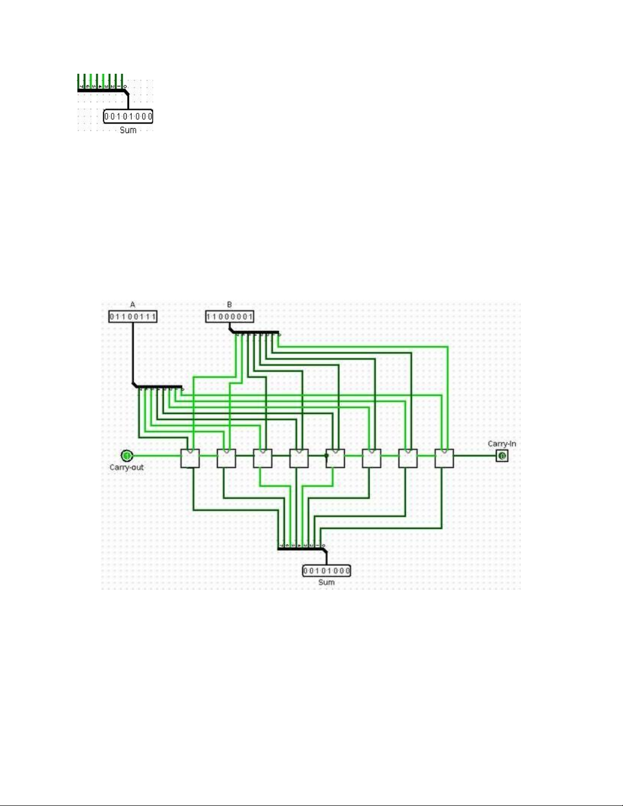
The Add-8 circuit that you build should look approximately as follows. Note that
it must have a carry-in input. (We won't actually need the carry-out for the purposes
of this lab.) It is shown here adding the number 01100111 to 11000001, with a carry- in of zero:
It can be touchy connecting all the wires! You will find that you need to release and
re-press the mouse in the middle of dragging a wire in order to get two angles in the
wire. I found it easier to drag from the adder to the splitter, instead of from the splitter
to the adder. And be prepared to hit Control-Z a lot to undo missteps! lOMoAR cPSD| 58702377
Review 4: Eight-bit Subtract
For this Review, you should make an 8-bit subtraction circuit named "Subtract-
8". This is easier than it might seem, since subtracting A−B is the same as adding A+
(−B). However, −B can be computed by negating B and adding 1. This means that A+(−B) = A+(NOT B)+1.
To make a subtraction circuit, start by adding an 8-bit adder to the circuit. Add
two 8-bit inputs and one 8-bit output. The first input can be directly connected to the
first input of the adder. The output can be directly connected to the output from the
adder. The only question is, what to do with the second input? How to handle the "(NOT B)+1"?
We actually have a nice way to deal with the +1 at the end: The adder circuit has
a carry-in input. By connecting a constant value 1 to the adder's carry-in, we can add
the final 1 that we need for subtraction. Logisim has a component called a "Constant"
listed under wiring. Add a Constant to your subtraction circuit, set its value to 0x1,
and connect it to the carry-in input of the adder.
Using the carry-in to add the extra 1, the second input to the subtraction circuit
only needs to be NOTed. You can do that by passing it thorough a single NOT gate
whose "Data Bits" property has been set to 8. The output of the NOT connects to the
second input of the adder. Once you've done that, you should have a working
subtraction circuit. It is not necessary to connect the carry-out of the adder to anything. Review 5: Tiny ALU
For this Review, you should build a tiny ALU. You can construct it in the circuit
named "main" that was originally the only circuit listed in the Logisim window. To edit
it, double-click on "main" in the list of circuits in the upper left portion of the window.
An ALU (arithmetic-logic unit) in a computer performs arithmetic and logical
operations on numbers. The same ALU can perform several different operations, and
it has control wire inputs to tell it which operation to perform.
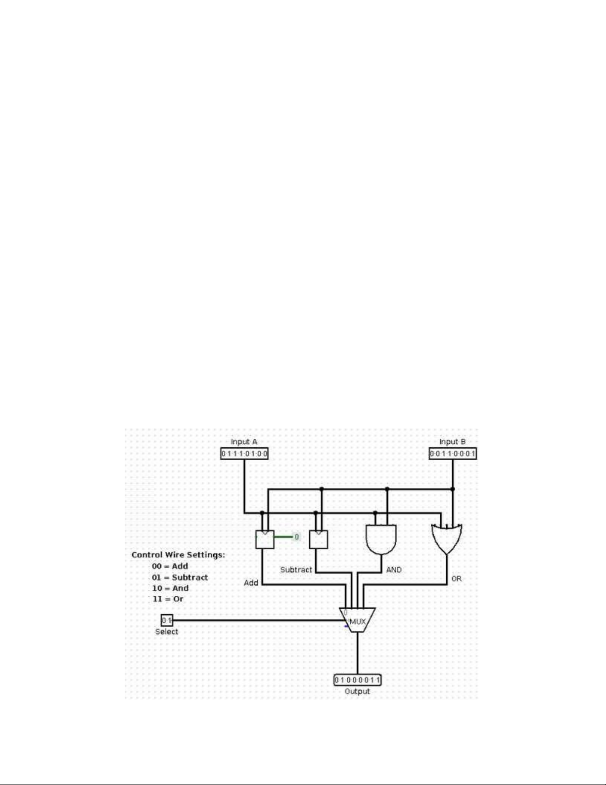
The ALU that you build for this Review will do four operations on 8-bit
numbers: Add, Subtract, And, and Or. To select which operation to perform, there will
be two wires, which can be represented by one 2-bit input. If the control wires are set
to 00, the ALU should add its two inputs; if they are set to 01, the ALU should lOMoAR cPSD| 58702377
subtract; if they are set to 10, it should apply AND; and if they are set to 11, it should apply OR.
To add and subtract numbers in your ALU, you can use the 8-bit adder and the
8-bit subtracter that you created earlier in the lab.
I won't force you to build your own 8-bit OR circuit and an 8-bit AND circuit. In
fact, you can simply use Logisim's OR and AND gates. One of the properties of a
gate in Logisim is the number of "Data Bits." By setting that property to 8, you get a
gate that can be connected to 8-bit inputs and outputs. In effect, an AND gate with 8
data bits is made up internally of 8 one-bit AND gates. It computes the bitwise logical
AND of its two 8-bit inputs. So, you can use one of Logisim's AND gates, with its
"Data Bits" property set to 8, as the 8-bit AND circuit in your ALU. Similarly for the OR circuit.
The funny thing about an ALU is that it actually performs all of its operations in
all cases. The control wires just determine which of the results gets to the output.
What you need here is a multiplexor. In this case, you can use the Multiplexor
component that is built into Logisim; you will find it in the "Plexors" section of the
component palette. (Alternatively, of course, you could build the multiplexor that you
need from basic gates; we saw in class how that is done.) Here is what my ALU looks like: lOMoAR cPSD| 58702377
Don't forget to test all of your circuits to make sure that they are working
correctly before you turn in your file!
The ALU that you have built contains two 8-bit adders (one inside the
subtraction circuit). It is possible to build an ALU with only one adder, which does
both addition and subtraction. The carry-in of the adder must be 0 for addition and 1
for subtraction. The second 8-bit input to the adder must be NOTed when doing
subtraction, but not when doing addition. You have to use the control wires to make
sure that the inputs to the adder are set correctly both for addition and for subtraction.
Build a second ALU using these ideas for a little extra credit.
Tài liệu liên quan:
-

Arduino UNO R3 Reference Manual: Features & Applications Guide | Môn Hệ thống nhúng trong công nghiệp - Đại học Sư phạm Kỹ thuật Thành phố Hồ Chí Minh
123 62 -

DALI LED Driver Control System Using Raspberry Pi3: Design & Implementation | Môn Hệ thống nhúng trong công nghiệp - Đại học Sư phạm Kỹ thuật Thành phố Hồ Chí Minh
120 60 -

Báo cáo tuần 1: Hệ thống nhúng và Cài đặt MPLAB, XC18 | Môn Hệ thống nhúng trong công nghiệp - Đại học Sư phạm Kỹ thuật Thành phố Hồ Chí Minh
103 52 -

Đo mực nước hiển thị lên web online sử dụng cảm biến siêu âm có buzzer cảnh báo đầy | Môn Hệ thống nhúng trong công nghiệp - Đại học Sư phạm Kỹ thuật Thành phố Hồ Chí Minh
109 55